Configuration of the Tool LEDs
The different LED indicators on the tool are configured to be controlled by one of the available output signals.
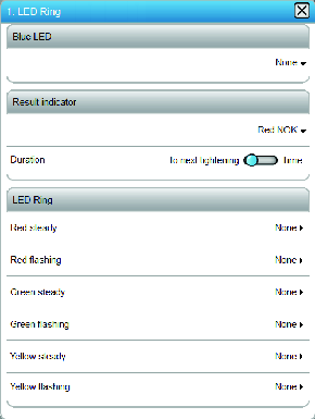
Blue LED
The blue LED will be lit for a configurable duration of time, or configured to be lit until the following tightening. It is lit on the signal chosen by the configuration.
Result indicator
The result indicator decides how and for how long the LEDs are lit on tightening results. A pre-configured pattern is selected from a shortcut menu. This pattern can be a combination of tightening results.
Signal | Description |
|---|---|
Off | No LEDs are activated after the tightening, regardless of the result |
Green | If a result indicator is selected, a green light is the default signal if the tightening is terminated correctly (OK). |
Red:high:yellow:low | If the tightening is terminated incorrectly (NOK); a red LED indicates that the final value is too high, or a yellow LED indicates that the value is too low. Red and yellow can be lit simultaneously (e.g. in case of too high torque, and too low angle). |
Red:high(prio):yellow:low | If the tightening is terminated incorrectly (NOK); a red LED indicates that the final value is too high, or a yellow LED indicates that the value is too low. Red and yellow cannot be lit simultaneously. Only red is lit in case of simultaneous high and low values. |
Red:NOK:yellow:low | A red LED indicates that the tightening is terminated incorrectly (NOK). An additional yellow LED can indicate if the value is too low. |
Red:NOK | A red LED indicates that the tightening is terminated incorrectly (NOK). No additional LEDs are shown. |
LED ring
The LED ring decides how the LEDs behave between the tightenings. The LED ring consists of three circles of LED lamps. One circle of red LEDs, one circle of yellow LEDs and one circle of green LEDs. Each circle can have a steady signal or a flashing signal. This provides a total of six different signals that can be connected to the LED ring.
A LED is turned on only when no tightening is ongoing and when the controlling output signal is activated.
A LED is turned off when the maximum time is exceeded. Only applicable if the signal type is an Event.
A LED is turned off when the next tightening is started.
A LED is turned off when the controlling output signal is deactivated. Only applicable if the signal type is an State.


