Counter
Overview

Pos | Part | Function |
|---|---|---|
A | Display | Displays values and settings. |
B | Switch left (SW-L) | Sets values or settings. Shows the information on the display and is also used with the button SW-R to change values or settings. |
C | Red-yellow LED | Shows alarms. |
D | Magnetic switch right (SW-R) | Changes values or settings. Activates with a magnet and is used with the button SW-L. |
E | Green LED | Shows alarms. |
Battery
Use battery CR2450N.
User mode
The following information displays when you press the button SW-L. To change between the information, press the button while showing the previous information.
Code | Information |
|---|---|
CNT TOOL | Numbers of drilled holes with the drill bit. It is counting down from a set value. |
CNT SERV | Numbers of drilled holes with the PFD. It is counting down from a set value. |
DRL DLAY | Seconds for the drill to move before the counter detects it as a drilled hole. Delays the PFD if it has a rapid advance function, otherwise the counter will count the rapid advance move as a drilled hole. |
CNT GLOB | Total drilled holes with the PFD. Counting up. |
CNT TIME | Number of hours of drilling with the PFD. |
VAL TOOL MX | Programmed values of maximum drilled holes with the drill bit. It is from this value the CNT TOOL is counting down. |
VAL SERV MX | Programmed values of maximum drilled holes with ADU before maintenance. It is from this value the CNT SERV is counting down. |
ALM TOOL | Alarm value, 6% of the numbers programmed for tool. The value where the counter sets off an alarm that it is time to change the drill bit. |
ALM SERV | Alarm value, 6% of the numbers programmed for ADU maintenance. The value where the counter sets off an alarm that it is time to change ADU. |
BATTERY VOLTAGE | The percentage of the battery that is left. Minimum 1.9 V. |
Changing setting and value
To change settings and values for the counter both the buttons SW-L and SW-R are to be used.
To enter the settings mode press the button SW-L and simultaneously hold a magnet over the button SW-R . After that use the button SW-L to go through the values that can be changed and to modify digits. The button SW-R is used as an OK and next button (it has to be made within a few seconds). This is also seen at the bottom of the display.
Code used to modify values | Being modified |
|---|---|
RST TOOL | Resets the counter CNT TOOL and clears alarms. |
RST SERV | Resets the counter CNT SERV and clears alarms. |
PRG TOOL | Programs value VAL TOOL MX for CNT TOOL. |
PRG SERV | Programs value VAL TOOL MX for CNT SERV. |
PRG DLY | Programs DRL DLAY. |
REPL BAT | Safeguards the counter before battery replacement. |

Alarm
The following alarms can be seen on the counter LEDs, red-yellow and green.
Green LED | Yellow LED | Red | Signification of alarms |
|---|---|---|---|
Flash | Drilling detected. | ||
Flash | Flash | Warning concerning a less than 6% for ALM TOOL or ALM SERV during a drilling. | |
Flash | Warning concerning a less than 6% for ALM TOOL or ALM SERV. | ||
Flash | Flash | The limits of CNT TOOL or CNT SERV are exceeded during a drilling. | |
Flash | The limits of CNT TOOL or CNT SERV are exceeded. | ||
Flash | Flash | Flash | Low battery during a drilling. |
Flash | Flash | Low battery. | |
Fast flash | Replacement battery needed. |
Installing the counter
Required tools
Torx key
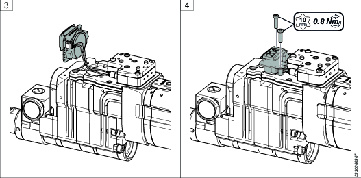
Remove the screws that fasten the air logic cover using an Allen key.
Remove the cover.
Connect the cable to the contact on the back of the counter.
Put the distances between the counter and the air logic. Install the counter and tighten it with the screws using a Torx key.

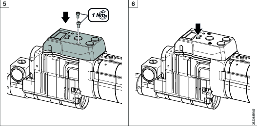
Make sure the cable is not squeezed.
Put the air logic cover back into original position and tighten the cover with the screws using an Allen key.
Press the button SW-L to begin using the counter.