Product Information
General Information
Safety Signal Words
The safety signal words Danger, Warning, Caution, and Notice have the following meanings:
DANGER | DANGER indicates a hazardous situation which, if not avoided, will result in death or serious injury. |
WARNING | WARNING indicates a hazardous situation which, if not avoided, could result in death or serious injury. |
CAUTION | CAUTION, used with the safety alert symbol, indicates a hazardous situation which, if not avoided, could result in minor or moderate injury. |
NOTICE | NOTICE is used to address practices not related to personal injury. |
Warranty
Product warranty will expire 12 months after the product is first taken into use, but will in any case expire at the latest 13 months after delivery.
Normal wear and tear on parts is not included within the warranty.
Normal wear and tear is that which requires a part change or other adjustment/overhaul during standard tools maintenance typical for that period (expressed in time, operation hours or otherwise).
The product warranty relies on the correct use, maintenance, and repair of the tool and its component parts.
Damage to parts that occurs as a result of inadequate maintenance or performed by parties other than Atlas Copco or their Certified Service Partners during the warranty period is not covered by the warranty.
To avoid damage or destruction of tool parts, service the tool according to the recommended maintenance schedules and follow the correct instructions.
Warranty repairs are only performed in Atlas Copco workshops or by Certified Service Partners.
Atlas Copco offers extended warranty and state of the art preventive maintenance through its ToolCover contracts. For further information contact your local Service representative.
For electrical motors:
Warranty will only apply when the electric motor has not been opened.
ServAid
ServAid is a portal that is continuously updated and contains Technical Information, such as:
Regulatory and Safety Information
Technical Data
Installation, Operation and Service Instructions
Spare Parts Lists
Accessories
Dimensional Drawings
Please visit: https://servaid.atlascopco.com.
For further Technical Information, please contact your local Atlas Copco representative.
Website
Information concerning our Products, Accessories, Spare Parts and Published Matters can be found on the Atlas Copco website.
Please visit: www.atlascopco.com.
Safety Data Sheets MSDS/SDS
The Safety Data Sheets describe the chemical products sold by Atlas Copco.
Please consult the Atlas Copco website for more information www.atlascopco.com/sds.
Installation of Vibrating Tools
We recommend using a minimum length of 300 mm (12") of flexible hose for compressed air between a vibrating tool and the quick-action coupling.
Country of Origin
For the Country of Origin, please refer to the information on the product label.
Dimensional Drawings
Dimensional Drawings can be found either in the Dimensional Drawings Archive, or on ServAid.
Please visit: http://webbox.atlascopco.com/webbox/dimdrw or https://servaid.atlascopco.com.
Overview
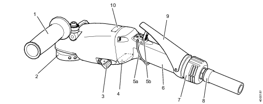
Main parts
|
Position |
Part |
Function |
|---|---|---|
|
1 |
Support handle |
Adjustable for a flexible working position for left or right handed operator. |
|
2 |
Auto balancer |
Reduces vibrations. |
|
3 |
Spindle locking button/Wheel guard adjustment |
Dual functionality. Locking spindle by pushing forward. Adjusting wheel guard by pulling backward. |
|
4 |
Data plate |
Shows general information about the tool. |
|
5 |
Security mechanism |
A two-step function for a safe start and stop of the tool. Press the release arm (5a) forward to release the safety looking arm (5b) |
|
6 |
Throttle handle |
Offers an ergonomic, comfortable and safe grip as well as good temperature insulation. |
|
7 |
Exhaust air outlet |
Allows adjustable direction of exhaust air in 360 degrees for healthy and comfortable operations. |
|
8 |
Whip hose |
Facilitates air connection handling and protects the tool from impurities. |
|
9 |
Throttle lever |
Starts and stops the tool. |
|
10 |
Sign |
Shows the tools nominal speed. |
Technical Product Data
Technical Product Data can be found on either ServAid, or the Atlas Copco website.
Please visit: https://servaid.atlascopco.com or www.atlascopco.com.
Service Overview
Service Recommendations
Preventive maintenance is recommended at regular intervals. See the detailed information on preventive maintenance. If the product is not working properly, take it out of service and inspect it.
If no detailed information about preventive maintenance is included, follow these general guidelines:
Clean appropriate parts accurately
Replace any defective or worn parts
Service interval overview
The table below shows the recommended service intervals for this tool, including what parts to service after 350, 700 and 1 000 working hours.
The 1 000 hours service must only be carried out by authorized workshop or qualified service technician.
350 hours service | 700 hours service | 1 000 hours service |
|---|---|---|
Inspect tool visually | Inspect tool visually | Inspect tool visually |
Change oil | Change oil | Change oil |
Clean filters | Clean filters | Clean filters |
Service turbine | ||
Service spindle |
Installation
Installation Requirements
Air quality
Poor air quality may cause damage to the tool and reduce the performance.
-
For optimum performance and maximum product life we recommend the use of compressed air with a maximum dew point of +10°C (50°F). We also recommend to install an Atlas Copco refrigeration type air dryer.
-
Use a separate air filter which removes solid particles larger than 30 microns and more than 90% of liquid water. Install the filter as close as possible to the product and prior to any other air preparation units to avoid pressure drop.
-
Lubrication free tools are a better choice from an environmental perspective.
-
Lubrication will shorten the life time of the turbine motor and once lubricated, you will need to continue with the lubrication.
Compressed Air Connection
For correct air pressure and hose size, see the Technical Product Data on - https://servaid.atlascopco.com or www.atlascopco.com.
Make sure that the hose and couplings are clean and free from dust before connecting to the tool.
Installation Instructions
Visual inspection - air installation
Inspect the air installation visually from the supply point to the tool before use.
Hose
Couplings
System pressure
Air filter
Look for any damage that can compromise the safety of the tool.
Visual inspection - tools and accessories
Inspect the tool and its parts visually before use.
The parts in the list below may vary depending on model.
Wheel guard or Backing pad
Adapters, nuts or flange washers
Support handle
Throttle lever and security mechanism
Autobalancer
Spindle
Look for any damage, grease or oil leakage that can compromise the safety of the tool.
Installation overview
Legend to page 2
-
Recommended torque
-
Whip hose length
-
Hose diameter
-
Max working air pressure
-
Max free speed
-
Recommended torque
Operation
Ergonomic Guidelines
Consider your workstation as you read through this list of general ergonomic guidelines to identify areas for improvement in posture, component placement, or work environment.
Take frequent breaks and change work positions frequently.
Adapt the workstation area to your needs and the work task.
Adjust for a convenient reach range by determining where parts and tools need to be located to avoid static load.
Use workstation equipment such as tables and chairs appropriate for the work task.
Avoid work positions above shoulder level or with static holding during assembly operations.
When working above shoulder level, reduce the load on the static muscles by lowering the weight of the tool, using for example torque arms, hose reels or weight balancers. You can also reduce the load on the static muscles by holding the tool close to the body.
Take frequent breaks.
Avoid extreme arm or wrist postures, particularly during operations requiring a degree of force.
Adjust for a convenient field of vision that requires minimal eye and head movements.
Use appropriate lighting for the work task.
Select the appropriate tool for the work task.
In noisy environments, use ear protection equipment.
Use high-quality inserted tools and consumables to minimize exposure to excessive levels of vibration.
Minimize exposure to reaction forces.
When cutting:
A cut-off wheel can get stuck if the cut-off wheel is bent or not guided properly. Use the correct flange for the cut-off wheel and avoid bending the cut-off wheel during operation.
When drilling:
The drill might stall when the drill bit breaks through. Use support handles if the stall torque is high. The safety standard ISO11148 part 3 recommends using a device to absorb a reaction torque above 10 Nm for pistol grip tools and 4 Nm for straight tools.
When using direct-driven screwdrivers or nutrunners:
Reaction forces depend on the tool settings and joint characteristics. Strength and posture determine the amount of reaction force that an operator can tolerate. Adapt the torque setting to the operator's strength and posture and use a torque arm or reaction bar if the torque is too high.
In dusty environments, use a dust extraction system or wear a mouth protection mask.
Configuration Instructions
Configuration options
The table below shows the options for BSP and NPT configuration with applicable attachments.
For Ordering No see section Accessories. For installation instruction see section Operation.
Pos. | Item | Sanding, BSP | Sanding, NPT |
|---|---|---|---|
1 | Backing pad | Ø 180mm | Ø 7” |
2 | Fibre disc | ||
3 | Nut locking backing pad | M14 | UNC 5/8”-11 |
Service tool | Face spanner, CC.30 × Ø 5 mm | Face spanner, CC.30 × Ø 5 mm | |
4 | Locking kit | Accessory included, M6 × 20 | Accessory included, UNC 1/4” |
Service tool | Hexagon key, 4mm | Hexagon key, 4mm | |
Recommended torque | 15 Nm | 11 ftlb |
Lever assembly options
Remove the lever by using a screwdriver.
Remove the two screws that holds the release holder.
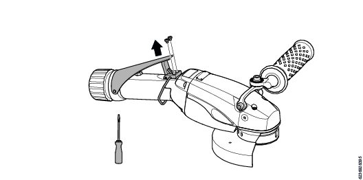
Seal the screw holes with the two screws in the lever kit.
Push in the replacement lever by using a screwdriver.

Operating Instructions
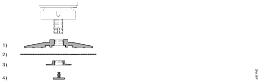
Installing backing pad
Before you start the installation
Visually inspect that the backing pad is not cracked or damaged.
Make sure that the backing pad has the appropriate hole dimensions.
Make sure that you have the correct abrasive for the application.
Make sure that the stated maximum speed of the backing pad is greater than or equal to the speed specified on the tool.
Required tools:
Face spanner
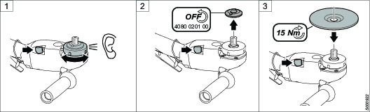
Press the spindle lock button forward and keep it pressed while turning the autobalancer into locked position. Listen for a sound indicating correct position.
Press the spindle lock button forward and keep it pressed while removing the adapter (if attached) using a face spanner.
Fit the backing pad and the abrasive on the spindle.
Attach the flange washer using the face spanner to the recommended torque. Attach the locking kit using the allen key to the recommended torque.
Make sure that the backing pad spins correctly.

Adjusting support handle
Required tools:
Allen key (stored within the handle)
Loosen the support handle using an allen key.
Adjust the support handle in a suitable position.
Tighten the support handle with the screw to the recommended torque.

Verifying free speed
Required tools:
Face spanner
Tachometer
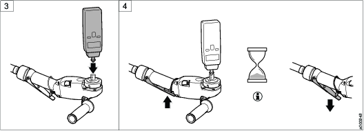
Press the spindle lock button forward and keep it pressed while tightening the adapter using a face spanner.
Connect the tool to the air supply.
Put a tachometer in the spindle hole.
Start the tool and measure the speed at a pressure of 6.3 bar.

Make sure that the throttle lever is pressed down to the bottom and measure the speed for at least 1 minute
Remove the tachometer.
Verify the free speed on the tachometer with the speed marked on the tool.


Operating the sander
-
Connect the tool to the air supply (if not already connected).
-
Direct the air exhaust on the throttle handle away from the operator.
-
Press the release arm forward to release the security mechanism.
-
Press down the throttle lever to start the tool.
Replace the throttle lever if it is not working properly.

Service
Maintenance Instructions
Service Recommendations
Preventive maintenance is recommended at regular intervals. See the detailed information on preventive maintenance. If the product is not working properly, take it out of service and inspect it.
If no detailed information about preventive maintenance is included, follow these general guidelines:
Clean appropriate parts accurately
Replace any defective or worn parts
Preventive Maintenance
Service interval overview
The table below shows the recommended service intervals for this tool, including what parts to service after 350, 700 and 1 000 working hours.
The 1 000 hours service must only be carried out by authorized workshop or qualified service technician.
350 hours service | 700 hours service | 1 000 hours service |
|---|---|---|
Inspect tool visually | Inspect tool visually | Inspect tool visually |
Change oil | Change oil | Change oil |
Clean filters | Clean filters | Clean filters |
Service turbine | ||
Service spindle |
Service instructions
Changing oil
Required tools:
Vice
Screwdriver TX20
Torque wrench
Spare parts
Service kit including oil syringe filled with 7 ml Turbine Gearbox Oil 32
(available to order from Atlas Copco).
Torque converter
3 Nm = 2.2 ftlb
6 Nm = 4.4 ftlb
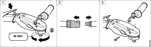
Connect the tool to the air supply (if not already connected).
Always lock auto-balancer with applicable part before running the tool.
Run the tool at idle speed for 60 seconds.
Disconnect the compressed air supply hose from the tool.
Remove the support handle from the tool.
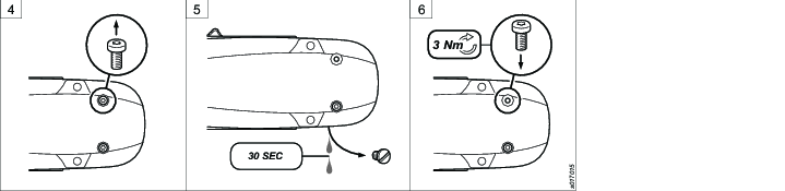
Place the tool in a horizontal and stable position. Remove the spindle screw.
Remove the oil plug. Keep the tool in a horizontal position.
Drain the oil from the tool for at least 30 seconds.
Fit the spindle screw in position and tighten with recommended torque.
Place the tool in a vice in a vertical position with the oil filling hole downwards. Fill the tool with 7 ml Turbine Gearbox Oil 32 using an oil syringe (included in the service kit)
Make sure that the tool is filled with oil within the recommended range. High oil level will cause overheating, while low oil level can cause gear damage over time.
Clean the magnet on the oil plug from oil and particles using a clean lint-free cloth.
Fit the oil plug in position and tighten with recommended torque.
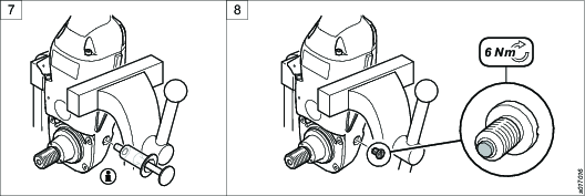
Cleaning the fine air filter
Required tools:
Vice
Torque wrench
Screwdriver
Blow gun
Spare parts: At 1 000 hours service the filter shall be replaced.
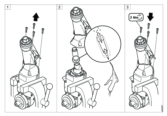
Position the tool in a vice.
Remove the four screws from the handle using a torx screwdriver.
Remove the handle from the motor housing.
Remove the fine air filter from the valve housing.
Clean the fine air filter using a blow gun.
Replace the fine air filter if any damage or malfunction is detected.
Fit the cleaned or the new fine air filter in the valve housing.
Proceed with caution not to release the over speed shut- off mechanism.
Fit the handle to the motor housing.
Tighten the four screws in the handle to recommended torque.
Cleaning the coarse air filter
Required tools:
Vice
Torque wrench
Wrench (3/8”)
Blow gun
Spare parts: At 1 000 hours service the filter shall be replaced.
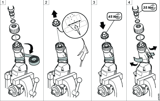
Position the tool in a vice. Lock the throttle lever to the throttle handle with tape.
Disconnect the air adapter from the handle using a wrench.
Disassemble the 360-outlet adapter from the handle.
Disassemble the screw cap from the handle using a wrench.
Clean the coarse air filter using a blow gun.
Replace the coarse air filter if any damage or malfunction is detected.
Assemble the cleaned or new course air filter with the o-ring in the screw cap.
Fit the screw cap in the handle and tighten using a wrench to recommended torque.
Assemble the 360-outlet adapter with the o-ring to the handle.
Tighten the air adapter with the spring to the screw cap using a wrench to recommended torque.
Remove the tape.
Lubrication Instructions
Lubricating guide
Use lubricants of good quality. The oils and greases listed in the lubrication table are examples of lubricants that can be recommended.
Brand | General purpose Bearings |
|---|---|
BP | Energrease LS-EP2 |
Castrol | Spheerol EP L2 |
Esso | Beacon EP2 |
Q8 | Rembrandt EP2 |
Mobil | Mobilegrease XHP 222 |
Shell | Alvania EP2 |
Texaco | Multifak EP2 |
Molycote | BR2 Plus |
Troubleshooting
Troubleshooting
The table below shows the most common troubleshooting procedures. Note that some actions must only be carried out by authorized workshops or qualified service technicians.
Problem | Reason | Action |
|---|---|---|
Tool does not start | No air flow to the tool | Check air connection |
Overspeed protection device activated | * | |
| Motor jammed | * |
Inconsistent idling speed | Unstable air pressure | Check air pressure regulator |
| Worn governor | * |
Low power | Low air pressure | Check air pressure |
| Wrong length or dimension of supply hose | Check air connection |
| Blocked filters | Clean or change the corse & fine filter |
| Too humid air (high dew point) | Check the compressor |
| Too much oil in gear box | Check oil level |
| Worn throttle valve | * |
| Worn turbine | * |
| Worn governor | * |
Oil in exhaust air | Lubricated air | Oil in the air is not recommended |
| Leak from turbine seal | * |
| Leak from O-ring on diffuser | * |
| Leak from overspeed pin | * |
Oil leakage at spindle | Loose screws or oil plug | Tighten screws |
| Worn oil seal | * |
| Damaged O-ring on plate | * |
| Damaged spindle bearing | * |
| Missing seal on oil plug or screws | Replace seal |
Tool starts unexpectedly | Damaged throttle valve | * |
| Valve pin jammed in start position | Change pin & guide |
| Damaged safety lock mechanism | Change mechanism |
Vibrations | Worn or damage grinding wheel | Change wheel |
| Autobalancer not working properly | Change autobalancer |
Too high idle speed | Governor | * |
Motor housing too hot | Too much oil in gear box | Check oil level |
Abnormal sound | Too little oil in gear housing | Check oil |
| Damaged gear | * |
| Incorrect gear play | * |
| Worn motor bearings | * |
* This service must only be carried out by authorized workshop or qualified service technician.
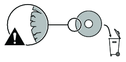
Recycling
Environmental Regulations
When a product has served its purpose it has to be recycled properly. Dismantle the product and recycle the components in accordance with local legislation.
Batteries shall be taken care of by your national battery recovery organization.
Recycling information

|
|
Part |
Recycle as |
|---|---|---|
|
1 |
Motor housing |
Metal, Aluminum |
|
2 |
Motor housing insulation |
Plastics, Other, POM |
|
3 |
Motor complete |
Metal, Aluminum |
|
4 |
Throttle handle insulation |
Plastics, Other, POM |
|
5 |
Filter tube |
Plastics, Other, PA66 GF30 |
|
6 |
Spindle complete |
Metal, Steel |
|
7 |
Autobalancer |
Metal, Steel |
|
8 |
Support handle |
Metal, Aluminum |
|
9 |
Support handle holders |
Metal, Steel |
|
10 |
Wheel guard |
Metal, Steel |
|
11 |
Throttle handle lever |
Metal, Steel |
|
12 |
Throttle handle |
Metal, Aluminum |
|
13 |
Air adapter |
Metal, Steel |
|
14 |
Outlet adapter |
Plastics, Other, PA66 |
|
15 |
Air adapter |
Metal, Steel |