Torque (Control) / Angle (control) OR
This strategy guides the operator in reaching the desired target torque and angle.
Parameter | Description |
|---|---|
Required tag number | A specific number must be written in the TAG of the end fitting tool. |
Name | Name of the tightening program. |
Rundown complete torque | Torque value from which the tightening operation starts. |
Torque min | Lower torque limit. |
Torque max | Higher torque limit. |
Change bolt limit | If the torque applied reaches this limit, the message Change screw is shown on the wrench display. |
Target torque | The torque target. |
Final angle monitoring torque | Torque value from which the angle measurement starts (usually set to 50% of the Target torque). |
Angle min | Lower angle limit. |
Angle max | Higher angle limit. |
Target angle | The angle target. |
Torque units | Select the unit of measurement. |
Angle limit for rehit | If the Torque min value is reached within the specified angle, the message Joint already tightened is shown on the wrench display. |
Measure torque at | Select between Torque peak and Angle peak. |
Torque correction coefficient | When extensions are used, the wrench measurement might be compensated to show a more accurate torque value. To calculate the correction coefficient, please refer to How to calculate the Torque Correction Coefficient. When extensions are not used, Torque correction coefficient = 1. |
Angle correction | When extensions cause additional wrench bending, the wrench angle measurement can be compensated to show a more accurate angle value. When extensions are not used, Angle correction = 0. |
Batch size | Number of tightenings the batch will perform. |
Max consecutive NOK | Number of accepted consecutive NOK to have an OK result. |
End cycle time | Starts when the torque goes below the Rundown complete torque after reaching the 3rd percentage. |
Ratchet time | Starts when the torque goes below the Rundown complete torque without reaching the 3rd percentage value. This allows the operator to release the torque for a while and recharge during the tightening operation. |
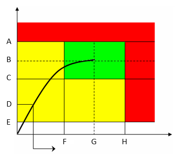
A | Torque max | B | Target torque |
C | Torque min | D | Final angle monitoring torque |
E | Rundown complete torque | F | Angle min |
G | Target angle | H | Angle max |
The green area defines the OK result area.
During the tightening operation, LEDs, buzzer and vibration are activated as follows:
LEDs:
First radial gradient LEDs (two directions): torque over the 1st percentage (30% of the Target Torque - if Torque peak is specified in the tightening program). Angle over the 1st percentage (30% of the Target Angle - if Angle peak is specified in the tightening program).
Second radial gradient LEDs (two directions): torque over the 2nd percentage (60% of the Target Torque - if Torque peak is specified in the tightening program). Angle over the 2nd percentage (60% of the Target Angle - if Angle peak is specified in the tightening program).
Third radial gradient LEDs (two directions): torque and angle are within the minimum and maximum limits; torque or angle have reached the target value; torque or angle go over the maximum value.
Torque peak:
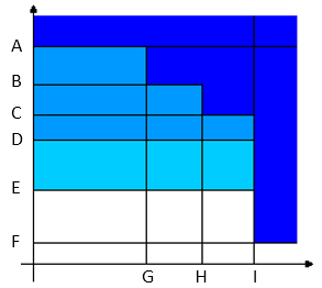
Torque vs. Angle A
Torque max
B
Target torque
C
Torque min
D
2nd percentage
E
1st percentage
F
Rundown complete torque
G
Angle min
H
Target angle
I
Angle max
Angle peak:
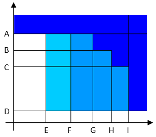
Torque vs. Angle A
Torque max
B
Target torque
C
Torque min
D
Rundown complete torque
E
1st percentage
F
2nd percentage
G
Angle min
H
Target angle
I
Angle max
Buzzer:
The beep starts when the torque goes over the Rundown complete torque value; the signal increases when the 1st percentage, the 2nd percentage, torque and angle are within the minimum and maximum limits, and the Torque max or Angle max are reached.
If Angle peak is specified in the tightening program, the buzzer signal monitors the angle instead of the torque.
Vibration:
Starts together with the third radial gradient LEDs.
Torque/angle results:
If torque/angle do not exceed the torque/angle limits, the result is taken at the Torque peak or Angle peak (as specified in the tightening program).
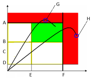
If the torque/angle goes over the limit, the result is taken as follows:

Torque vs. Angle A
Torque max
B
Torque min
C
Final angle monitoring torque
D
Rundown complete torque
E
Angle min
F
Angle max
G
When the Measure torque at is set to Torque peak, and the torque (or both torque and angle) goes over the limits, the result is taken at the torque peak.
H
When the Measure torque at is set to Torque peak, and only the angle goes over the limits, the result is taken at the angle peak.
Torque vs. Angle A
Torque max
B
Torque min
C
Final angle monitoring torque
D
Rundown complete torque
E
Angle min
F
Angle max
G
When the Measure peak at is set to Angle, and the angle (or both torque and angle) goes over the limits, the result is taken at the angle peak.
H
When the Measure peak at is set to Angle, and only the torque goes over the limits, the result is taken at the torque peak.
At the end of the tightening operation, LEDs, buzzer and vibration are activated as follows:
LEDs:
Blue LEDs: angle result between Rundown complete torque and Torque minTorque min, or torque between Torque min and Torque max but angle below the Angle min.
If Angle peak is selected in the tightening program, the Final angle monitoring torque value is used instead of the Rundown complete torque value.Green LEDs: torque and angle results within the minimum and maximum limits.
Red LEDs: torque result over Torque max, or angle result over Angle max.
Buzzer:
Two beeps indicate the end of the operation; if the final result is in the red area, the signal is continuous.
To stop the buzzer, start a new tightening operation or press a button on the tool controller.
Vibration:
Stays active until the torque applied is released.


