Mounting a Scanner or Tag to the Tool
When working on the assembly, use blunt plastic tweezers to avoid damaging parts or cables.
For torques and bolt sizes, refer to the applicable tool model in ServAid.
Steps 17 to 19 do not apply to ILM and ILT tool tags.
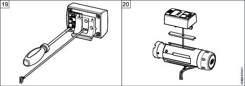
Remove the front part of the tool including the shaft.
Remove the four screws of the power module. Remove the power module.
Remove the five screws of the handle side cover. Remove the handle side cover.
Disconnect cables A and B from the handle module.
A
Torque transducer
B
Radio connector
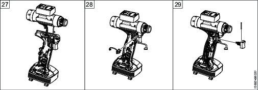
Remove the screw of the ground plate top. Remove the ground plate top.
Remove the LED cover.
Remove the label plates and the lids on both sides of the tool.
Remove the cable cover.
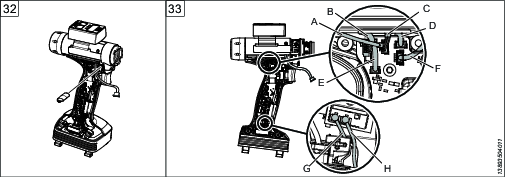
Disconnect cables A-F from the handle module and cables G and H from the radio module.
A
Speaker
B
Tool board TBP
C
HMI
D
Light and conf.
E
Motor temp.
F
Commutation
G
Antenna
H
Antenna
Remove the screw from the main board module. Remove the main board module and the reverse button.
Pull the trigger and remove the pin by pulling it upwards.
Remove the trigger and the pin.
Separate the handle module from the motor module.
Remove the torque transducer.
Remove the LED flexcard.
Remove the two mounting screws of the accessory attachment.
Remove the four screws of the accessory lid. Remove the lid.
Pull the accessory cable through the accessory lid and connect the cable to the accessory circuit board if applicable.
Put the accessory lid back in place and tighten the four screws.
Pull the accessory cable through the hole of the new cable cover and insert it in place while pulling the cable.
Position the accessory in place and tighten the two screws of the accessory attachment.
Pull the cable under the motor module cover.
Reattach the LED flexcard.
Reattach the torque transducer.
Reinsert the label plates on both sides of the tool.
Reattach the LED cover.
Reattach the motor module to the handle module.
Put the front light back in place.
Insert the pin into the trigger and put the trigger back in place.
Pull the trigger and pull the pin downwards.
Put the main board module back in place and tighten the screw.
Put the reverse button back in place.
Reconnect cables A-F to the handle module and cables G and H to the radio module.
A
Speaker
B
Tool board TBP
C
HMI
D
Light and conf.
E
Motor temp.
F
Commutation
G
Antenna
H
Antenna
Put the ground plate top back in place and tighten the screw.
Connect cables A-C to the handle module over the ground plate top.
A
Torque transducer
B
AUX
C
Radio connector
Put the handle side cover back in place and tighten the five screws.
Insert the shaft and fasten the front cover.
Put the power module back in place and tighten the four screws.