Torcflex Square Drive Tool
Hydraulic Torque Wrench
Product Information
General Information
Safety Signal Words
The safety signal words Danger, Warning, Caution, and Notice have the following meanings:
DANGER | DANGER indicates a hazardous situation which, if not avoided, will result in death or serious injury. |
WARNING | WARNING indicates a hazardous situation which, if not avoided, could result in death or serious injury. |
CAUTION | CAUTION, used with the safety alert symbol, indicates a hazardous situation which, if not avoided, could result in minor or moderate injury. |
NOTICE | NOTICE is used to address practices not related to personal injury. |
Warranty
Product warranty will expire 12+1 months after dispatch from Atlas Copco's Distribution Center.
Normal wear and tear on parts is not included within the warranty.
Normal wear and tear is that which requires a part change or other adjustment/overhaul during standard tools maintenance typical for that period (expressed in time, operation hours or otherwise).
The product warranty relies on the correct use, maintenance, and repair of the tool and its component parts.
Damage to parts that occurs as a result of inadequate maintenance or performed by parties other than Atlas Copco or their Certified Service Partners during the warranty period is not covered by the warranty.
To avoid damage or destruction of tool parts, service the tool according to the recommended maintenance schedules and follow the correct instructions.
Warranty repairs are only performed in Atlas Copco workshops or by Certified Service Partners.
Atlas Copco offers extended warranty and state of the art preventive maintenance through its ToolCover contracts. For further information contact your local Service representative.
Website
Information concerning our Products, Accessories, Spare Parts and Published Matters can be found on the Atlas Copco website.
Please visit: www.atlascopco.com.
ServAid
ServAid is a portal that is continuously updated and contains Technical Information, such as:
Regulatory and Safety Information
Technical Data
Installation, Operation and Service Instructions
Spare Parts Lists
Accessories
Dimensional Drawings
Please visit: https://servaid.atlascopco.com.
For further Technical Information, please contact your local Atlas Copco representative.
Safety Data Sheets MSDS/SDS
The Safety Data Sheets describe the chemical products sold by Atlas Copco.
Please consult the Atlas Copco website for more information www.atlascopco.com/sds.
Safety Warning
 Do not modify or subject any equipment or accessories to impact - Contact Atlas Copco for special tool applications or equipment modifications. Unauthorized modifications may lead to premature tool failure which may cause injury.
 Do not use electric pump in explosive or wet environment - If electric pump is used, ensure that extension cable, power supply and earthing meet electrical code. Be aware of electrical hazards, e.g. sparking and shocks.
 High hydraulic pressure hazards -
Use correct tools, hoses and fittings. Ensure all hose connections are fully connected, tight and leak free.
Keep clear off leaking hydraulic fluid. Clean any spillages.
Never exceed the maximum working pressure of the pump. Ensure hose and fittings are rated for 10000 psi (700 bar) dynamic working pressure. The maximum working pressure is permanently marked on the tool.
 Keep hands and fingers clear from pinch points - Pinch points exist around reaction area and when operating in tight spaces.
 Maintain equipment in good working order - Inspect for tool damage, cracks or wear and lubricate in line with equipment usage. Remove damaged equipment from service.
 One Person operation recommended - Only trained and competent personnel should control the operation of the tool. When two person tool operation cannot be avoided, a risk assessment must be performed that fully addresses the environment, application, co-ordination (between operators) and communication. The operator holding the torque wrench should control operations, i.e. the person in control does not necessarily have the control pendant in his possession, however they will give the commands to energize the pump/tool.
 Set tool reaction correctly - Incorrect or unstable reaction point may cause tool to move during operation, increasing operator risk. Poor reaction point selection may also lead to premature tool failure.
 Wear appropriate Personal Protective Equipment - Suitable for working with or close to high pressure hydraulic systems, e.g. Safety Glasses (EN166), Gloves, Safety footwear etc. Do not wear loose fitting gloves or gloves with cut or frayed fingers. Gloves can become entangled with the rotating drive/socket causing severed or broken fingers.
 Do not expose hoses to excessive bending, ensure hoses do not become trapped or damaged - Hose damage can result from thermal, mechanical or chemical abuse; causing the release of high pressure hydraulic fluid which may result in equipment damage and personal injury.
 Tool Selection - Select appropriate tool for the application based upon torque requirements and space constraints.
Country of Origin
For the Country of Origin, please refer to the information on the product label.
Dimensional Drawings
Dimensional Drawings can be found either in the Dimensional Drawings Archive, or on ServAid.
Please visit: http://webbox.atlascopco.com/webbox/dimdrw or https://servaid.atlascopco.com.
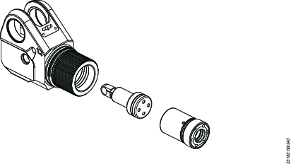
Overview
Square Drive Wrench Overview
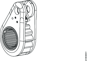
The Torcflex Square Drive Wrench (TF) is a professional hydraulic power tool that is designed to exert torque on industrial fasteners to make sure of correct tightening or loosening of an industrial bolted connection. The tool uses a double acting hydraulic cylinder to transfer linear force into rotation torque through a ratchet mechanism. The torque is controlled by adjusting the pressure applied to the hydraulic cylinder.
The tool includes the following main components:

A | Swivel manifold | A swivel manifold with hydraulic couplings for connection to an appropriate hydraulic power supply. |
B | Wrench housing | A wrench housing which contains the hydraulic cylinder and the ratchet mechanism. |
C | Square drive | A removable square drive with integrated retaining mechanism to allow the connection of sockets. |
D | Reaction arm | An adjustable reaction arm to absorb the reaction forces generated during tool operation. |
Technical Data
Power Supply Hydraulic Pressure All Models
Min 104 bar – Max 700 bar Min 1500 psi – Max 10000 psi |
Prod. No. | Square drive | Torque Range Min | Torque Range Max | Radius | Weight | ||||
|---|---|---|---|---|---|---|---|---|---|
(in) | (Nm) | (ft lb) | (Nm) | (ft lb) | (mm) | (in) | (kg) | (lb) | |
TF01 (Co-Axial) 8434240605 | 3/4 | 283 | 209 | 1885 | 1390 | 24.7 | 0.97 | 2.75 | 6.06 |
TF01 (Twin) 8434241015 | 3/4 | 283 | 209 | 1885 | 1390 | 24.7 | 0.97 | 2.92 | 6.44 |
TF03 (Co-Axial) 8434240993 | 1 | 658 | 485 | 4379 | 3230 | 32.8 | 1.29 | 5.47 | 12.06 |
TF03 (Twin) 8434240994 | 1 | 658 | 485 | 4379 | 3230 | 32.8 | 1.29 | 5.64 | 12.43 |
TF05 (Co-Axial) 8434241116 | 1 1/2 | 1137 | 839 | 7579 | 5590 | 39.1 | 1.54 | 9.21 | 20.3 |
TF05 (Twin) 8434241117 | 1 1/2 | 1137 | 839 | 7579 | 5590 | 39.1 | 1.54 | 9.38 | 20.68 |
TF08 (Co-Axial) 8434241149 | 1 1/2 | 1627 | 1200 | 10847 | 8000 | 44.6 | 1.76 | 12.35 | 27.23 |
TF08 (Twin) 8434241150 | 1 1/2 | 1627 | 1200 | 10847 | 8000 | 44.6 | 1.76 | 12.52 | 27.6 |
TF10 (Co-Axial) 8434241524 | 1 1/2 | 2343 | 1728 | 15619 | 11520 | 49.4 | 1.93 | 15.87 | 34.99 |
TF10 (Twin) 8434241525 | 1 1/2 | 2343 | 1728 | 15619 | 11520 | 49.4 | 1.93 | 16.04 | 35.36 |
Dimensions
Dimensional Drawings can be found either in the Dimensional Drawings Archive, or on ServAid: http://webbox.atlascopco.com/webbox/dimdrw or https://servaid.atlascopco.com.
Technical Product Data
Technical Product Data can be found on either ServAid, or the Atlas Copco website.
Please visit: https://servaid.atlascopco.com or www.atlascopco.com.
Accessories
Impact Sockets
TF tools are provided with a square drive for use with impact sockets. Only use good quality impact sockets that are rated to accept the full torque output of the tool being used.
Always secure the socket to the square drive with a pin and ring.
TF tools can be supplied with a range of standard optional accessories. Hex drives, square drives and alternative reaction arms are available. Application-specific accessories can be designed on request. Contact Atlas Copco for more information.
Optional Accessories
Square/Allen Drive Working Torque
TF/RT tools are supplied with a Square Drive as standard. Other drive sizes are available as accessories.
The table below shows the maximum torque capacity for various drive sizes:
Drive Size Inch or mm | Drive Type | Maximum Torque | |
ft lbs | Nm | ||
1/2” | Square | 397 | 538 |
3/4” | Square | 1390 | 1885 |
1” | Square | 3230 | 4379 |
1-1/2” | Square | 11520 | 15619 |
2-1/2” | Square | 52500 | 71180 |
1/2” | Hexagon | 353 | 479 |
5/8” | Hexagon | 689 | 934 |
3/4” | Hexagon | 1191 | 1615 |
7/8” | Hexagon | 1892 | 2565 |
1” | Hexagon | 2824 | 3829 |
1-1/4” | Hexagon | 5516 | 7479 |
1-1/2” | Hexagon | 9531 | 12922 |
1-3/4” | Hexagon | 15135 | 20520 |
2” | Hexagon | 22593 | 30632 |
12mm | Hexagon | 298 | 404 |
14mm | Hexagon | 473 | 641 |
17mm | Hexagon | 846 | 1147 |
19mm | Hexagon | 1182 | 1602 |
22mm | Hexagon | 1834 | 2486 |
27mm | Hexagon | 3390 | 4596 |
32mm | Hexagon | 5644 | 7652 |
36mm | Hexagon | 8036 | 10895 |
41mm | Hexagon | 11870 | 16094 |
46mm | Hexagon | 16765 | 22730 |
50mm | Hexagon | 21530 | 29190 |
ATEX Certification Information
ATEX
Only tools and equipment correctly certified and marked with ATEX symbol should be utilized in potential explosive zones.

Operator must read and understand all operating instructions prior to use!
This (additional) information and guidance must be used in conjunction with the Standard Product and Safety Instructions supplied with all Torcflex hydraulic torque wrenches.
ATEX Zone Operation: Additional care and attention should be applied when working within potentially explosive environments. Special consideration is required with respect to the tightening application and use of the Torcflex range of tools, the operator must perform a risk assessment prior to the use of any Torcflex hydraulic torque wrench within a potentially explosive (ATEX zoned) environment.
It is the operators’ responsibility to maintain the tool to ensure its safe operation within ATEX rated zones. Failure to comply with the maintenance recommendations will increase the likelihood of mechanical failure and therefore the chance of mechanical spark generation.
If the wrench shows any sign of malfunction, remove it from the ATEX zone before investigating the cause. DO NOT attempt to repair the wrench in the ATEX zone.
If the wrench is dropped, remove it from the ATEX zone before looking for damage. Do a pressure test and functional test before using it again.
Torcflex Wrench Inspection
Inspect the general condition of the Torcflex wrench before using the tool in an ATEX zone. Particular attention should be given to the drive components, i.e., the square or hexagon drive, ratchet, and drive pawls. Any parts that are in poor condition or that have had significant use must be replaced. During re-assembly, ensure that the parts are correctly lubricated in accordance with maintenance instructions.
System and Operational Considerations
Only use Torcflex torque wrenches in ATEX zones when connected with/to other ATEX declared or certified components, e.g., hoses and hydraulic pump.
Confirm electrical continuity through the torque wrench system. To prevent any static build up, suitably earth / electrically ground the system / pump.
Additional care should be taken when selecting reaction points and in the placement and support of the hydraulic torque wrench.
Ensure accessories and sockets used are in good operational order and suitable for use within potentially explosive atmospheres.
ATEX Code Definition
The ATEX code is: | |
|---|---|
| II 2 G Ex h IIC T4 Gb II 2 D Ex h IIIC T135°C Db -20°C ≤ Ta ≤ 40°C |
Description | Value | Definition |
|---|---|---|
Equipment group | II | Surface industry |
Equipment category Group II | 2 | High level of protection
|
Atmosphere
| G | Atmosphere containing Gas, Vapors or Mist |
D | Atmosphere containing Dust | |
Safety design | h | Mechanical product |
Gas group | IIC | Hydrogene/ Acetylene |
IIB | Ethylene | |
Dust group | IIIC | Surface combustible dust |
Max surface temperature in Gas atmosphere |
| T1 = 450°C T2 = 300°C T3 = 200°C T4 = 135°C T5 = 100°C T6 = 85°C |
Max surface temperature in Dust atmosphere |
| Example temperatures: T85°C T100°C T135°C T200°C T240°C |
Installation
Installation Requirements
General Installation Requirements
To operate Torcflex wrenches, connect the wrench to a hydraulic power pack with a hydraulic hose. For maximum efficiency and accuracy, use Atlas Copco torque wrench pumps and hoses. If Atlas Copco pumps and hoses are not used, make sure of the following before connecting Torcflex wrenches:
System requirements:
All system components must have a dynamic pressure rating of 700 bar (10,000 psi).
Pump requirements:
Maximum Advance Pressure: 700 bar (10,000 psi).
Maximum Retract Pressure: 120 bar (1,740 psi).
Remote-operated directional control valve for operating the double acting cylinder; the pressure must be released when switching between Advance and Retract.
For safety, the remote must be configured to automatically retract the tool if the button is released.
Adjustable pressure relief valve.
Calibrated pressure gauge (Class 1 Accuracy).
For screw-to-connect coupling systems, make sure that the Advance coupling is male and the Retract coupling is female. For more information, refer to section Connecting the System - Screw-to-Connect Coupling.
Torcflex wrenches fitted with screw-to-connect couplings use CEJN 232 couplings with ¼ NPT threads. Before using alternative brand couplings in the system, verify the compatibility. For more information, refer to section Connecting the System - Screw-to-Connect Coupling.
Hydraulic hose requirements:
Advance line − female to female coupling.
Retract line − male to male nipple.
Before connecting the system, do the following:
On electric pumps, make sure that the power supply is appropriate for the pump and minimize the length of extension cords.
On pneumatic pumps, make sure that the air supply is appropriate for the pump and minimize the length of air lines.
Look for any damage on the power and pendant cables before connecting the cables to the power supply.
Look for any damage on the hydraulic hoses and couplings before connecting the hoses to the system.
Inspect the oil level and fill if necessary.
Make sure that the pressure gauge is calibrated.
Make sure that the impact sockets are the correct size for the application.
Make sure that the impact sockets are free from damage.
Select a wrench based on the target torque for the application.
To prolong the lifespan of the wrench, do not operate the tool above 80% capacity for long periods. As with any machine, operating it continuously at maximum capacity will reduce its lifespan. It will also need maintenance and replacement of worn parts more often.
For applications where the back nut can rotate, make sure that a suitable backup wrench is available.
Installation Instructions
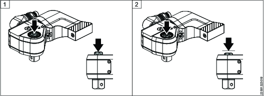
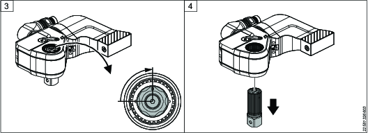
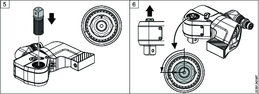
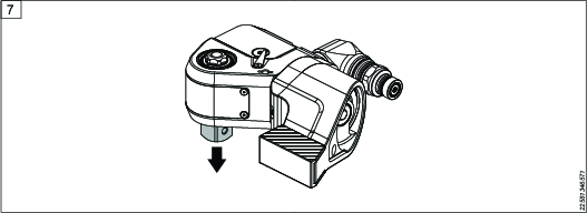
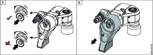
Setting the Drive
Press and hold the retainer button.
While pressed, turn the retainer button 90 degrees to unlock, then remove the drive from the wrench.
Insert the drive into the opposite side of the tool. Note that the button must remain in the unlock position while inserting (illustration 5). Turn the button 90 degrees until it pops up (illustration 6).
Pull the square drive to make sure that the installation is correct.
Once the drive is in the correct orientation, set the reaction arm before operation.
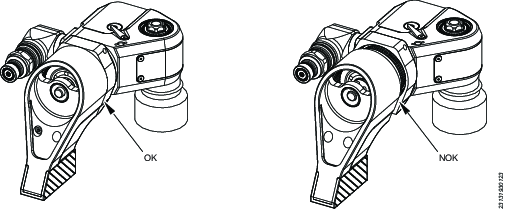
Setting the Reaction Arm
The diagram below shows acceptable (OK) and unacceptable (NOK) reaction arm positions.
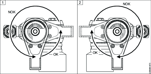
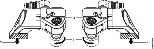
1 | Tightening position | 2 | Loosening position |
The tool has a built-in mechanism to help you to position the reaction arm at 90 degrees to the wrench.
Press the button to release the reaction arm.
Pull the spring-loaded reaction arm until it stops.
Rotate the arm 90 degrees until the arm stops at the desired position.
Push the arm onto the housing until the button makes a click sound.
Make sure that the button has popped out.
Pull the reaction arm to make sure that the installation is correct.
Installing the Support Handle
Make sure that the handle has the correct bolt size before you install the handle onto the wrench. Two support handle screw sizes are available; select the correct bolt size from the list.
TF01 / TFX02 = M6
TF03 / TFX04 = M8
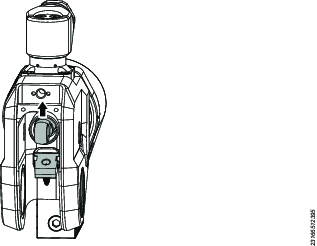
The wrench supports the installation of the support handle at three different positions.
Side positions, left or right:
Front position:
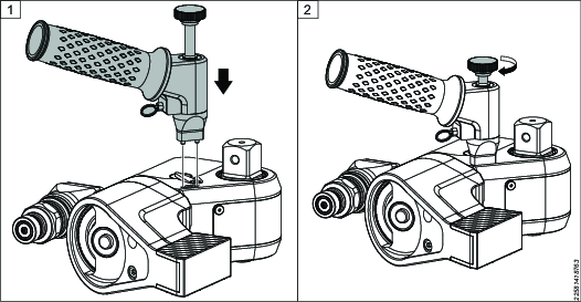
Preparing the Handle for Installation
Insert the bolt through the handle.
Screw the bolt into place with the thumbscrew.
Make sure that the bolt has axial float to allow installation.

Installing the Handle on the Wrench
Insert the dowel pin on the base of the handle into the holes on the wrench.
Hold the handle in place and screw the bolt into the wrench with the thumbscrew until tight.
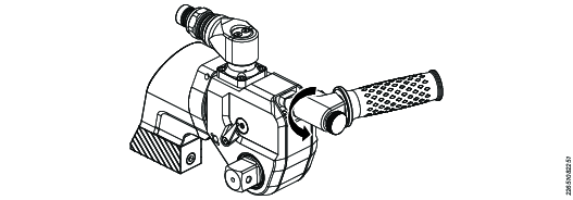
Adjusting the Handle Position
The bolt does not need to be loosened to adjust the handle position.
You can turn the support handle to 12 positions in 30-degree increments:
Pull and hold the ring pin.
Rotate the handle to the desired position and release the ring pin to lock.

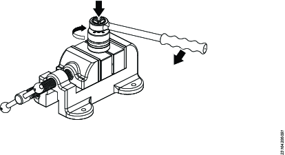
Releasing the Pressure
Torcflex wrenches can be supplied with either co-axial couplings or screw-to-connect couplings. The co-axial coupling system connects both the advance line and retract line with a single connection. The screw-to-connect coupling system requires the advance and retract lines to be connected individually. Before connecting, make sure that the couplings are clean and free of damage.
Before you try to connect or disconnect hydraulic couplings, make sure that there is no residual pressure in the pump.
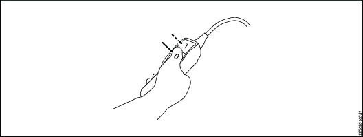
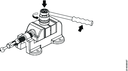
Electric Pumps
Press the button on top of the solenoid valve several times to release the pressure.

Pneumatic Pumps
Press the Stop [0] button on the remote control pendant to stop the pump.
Press and hold the Stop [0] button and press the Advance [1] button several times to cycle the solenoid valve.
1
Advance button
0
Stop button
All couplings should be easily connected and disconnected by hand. If not, look for damage or residual pressure in the system.
Connecting the System - Co-axial Coupling
The co-axial system connects both the advance and retract lines of the hydraulic circuit with a single coupling.
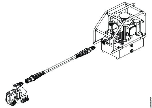
Connecting the Hose to the Pump
Hold the pump frame (1) to prevent the pump from moving during the connection. Position the hose nipple (2) in line with the pump coupling.
Firmly push the hose nipple and pump coupling together (2). A click is heard when the connection is complete.

The knurled collar on the pump coupling does not need to be drawn back during the connection.
Pull the hose (3) to make sure that the connection is correct.
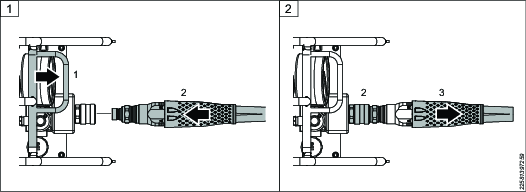
Connecting the Hose to the Wrench
Support the swivel manifold at the opposite side to the coupling (1). Position the hose coupling in line with the wrench nipple (2).
Firmly push the wrench nipple and hose coupling together. A click is heard when the connection is complete.
The knurled collar on the hose coupling does not need to be drawn back during the connection.
Pull the hose (3) to make sure that the connection is correct.
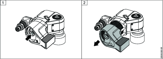
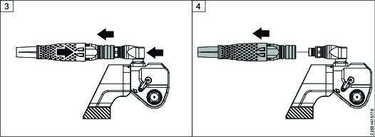
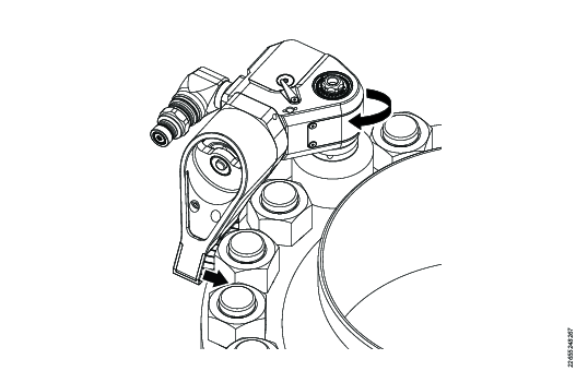
Disconnecting the Hose from the Pump
The co-axial coupling has a safety feature to prevent accidental disconnection during use. Learn how to disconnect the hose before using the equipment.
Hold the pump frame to prevent the pump from moving during the disconnection.
Push the hose nipple towards the pump (illustration 1) until the gap between the knurled collar and the nipple closes (illustration 2).
While holding the above position, push the knurled collar towards the pump (Illustration 3).
Pull the hose away from the pump and the connection will automatically spring apart (illustration 4).
If the connections are not pushed together and held, the knurled collar cannot move, therefore the couplings cannot be disconnected. This is a safety feature to prevent accidental disconnection.


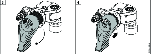
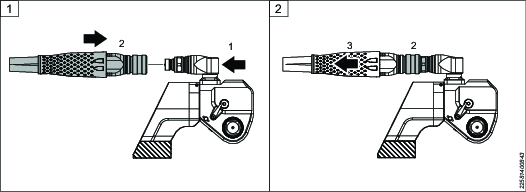
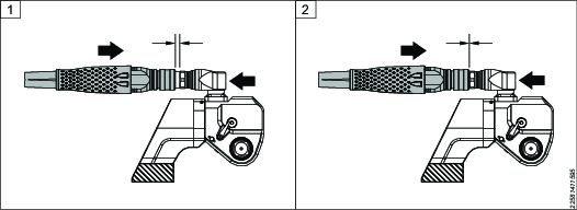
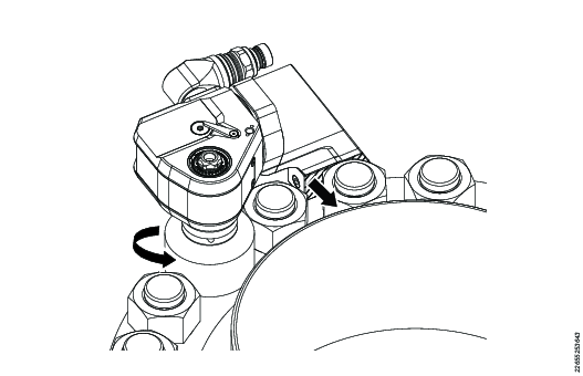
Disconnecting the Hose from the Wrench
The co-axial coupling has a safety feature to prevent accidental disconnection during use. Learn how to disconnect the hose before using the equipment.
Support the swivel manifold at the opposite side to the coupling.
Push the hose towards the wrench (illustration 1) until the gap between the knurled collar and the nipple closes, as shown in (illustration 2).
While holding the above position, pull the knurled collar away from the wrench (illustration 3).
Pull the hose away from the wrench and the connection will automatically spring apart (illustration 4).
If the connections are not pushed together and held, the knurled collar cannot move, therefore the couplings cannot be disconnected. This is a safety feature to prevent accidental disconnection.
Connecting the System - Screw-to-Connect Coupling
Atlas Copco pumps and hoses have the couplings pre-configured to operate Torcflex wrenches as shown below.
If you use non-Atlas Copco equipment to operate Torcflex wrenches, make sure that the couplings are configured as shown.

1 | Wrench | 2 | Pump |
Make sure that all couplings are connected properly with no gaps between the collars and the fittings. Never use wrenches or other tools to tighten or loosen couplers.

Make sure that the connectors are fully engaged and screwed tightly together.
Never use two twin hydraulic hoses between the pump and the tool. To avoid tool malfunction, do not reverse the connectors. Do not try to tighten or loosen any couplings under pressure.
Operation
Ergonomic Guidelines
Consider your workstation as you read through this list of general ergonomic guidelines to identify areas for improvement in posture, component placement, or work environment.
Take frequent breaks and change work positions frequently.
Adapt the workstation area to your needs and the work task.
Adjust for a convenient reach range by determining where parts and tools need to be located to avoid static load.
Use workstation equipment such as tables and chairs appropriate for the work task.
Avoid work positions above shoulder level or with static holding during assembly operations.
When working above shoulder level, reduce the load on the static muscles by lowering the weight of the tool, using for example torque arms, hose reels or weight balancers. You can also reduce the load on the static muscles by holding the tool close to the body.
Take frequent breaks.
Avoid extreme arm or wrist postures, particularly during operations requiring a degree of force.
Adjust for a convenient field of vision that requires minimal eye and head movements.
Use appropriate lighting for the work task.
Select the appropriate tool for the work task.
In noisy environments, use ear protection equipment.
Use high-quality inserted tools and consumables to minimize exposure to excessive levels of vibration.
Operating Instructions
Operation Safety

Working Pressure
All system components must have a dynamic pressure rating of 700 bar (10,000 psi). If other than Atlas Copco pumps and hoses are used, make sure that the equipment is suitable for use with Atlas Copco wrenches.
Pump Working Pressure:
Maximum Advance Pressure: 700 bar (10,000 psi)
Maximum Retract Pressure: 120 bar (1,740 psi)
Setting the Target Torque
Once the wrench is set up and connected to a pump, you must set the target torque output. To set the torque output, you must adjust the pressure output value at the pump.
Look at the calibration data sheet or the torque/pressure conversion chart for the tool to determine the pressure that will deliver the correct torque.
Loosen the lock nut on the pressure regulating valve, then loosen the thumbscrew until it is turning freely. Do not remove the thumbscrew.
Connect the pump to a suitable power supply.
With the wrench free to move, that is, not applied on a fastener, start the pump by pressing and releasing the Advance button [1] on the remote control pendant once.
Press and hold the Advance button [1].
The wrench piston advances to full stroke and the pressure builds up.
Monitor the pressure displayed on the gauge. Continue to hold the Advance button [1] and tighten or loosen the thumbscrew until the gauge reaches the target value.
Release the Advance button [1].
The wrench piston retracts.
Press and hold the Advance button [1] again. Make sure that you get the target value, then release the Advance button [1].
Hold the thumbscrew in position and lock the valve with the lock nut.
After locking the valve, press and hold the Advance button [1] once more and make sure that you still get the target value. Adjust if necessary.
The system is now ready for use.
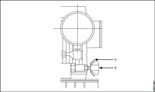
A | Knurled lock nut | B | T-handle |
1 | Advance button | 0 | Stop button |
Operating the Wrench
Before you start the tightening or loosening operations, make sure of the following:
The square drive is installed correctly and is set to give the desired drive direction.
The reaction arm is installed correctly, with the correct orientation for the application.
The impact socket is the correct size for the application.
The impact socket is secured to the square drive with a pin and ring.
There are no hydraulic leaks. To test, cycle the tool 3–4 times to allow the pressure to build to the target value. Examine the system for hydraulic leaks.
For applications where the rear nut can rotate, make sure that a suitable backup wrench is available.
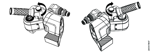
Checking the Drive Direction
Before you use the wrench, make sure that the direction of rotation is correct. The direction is indicated by the arrow on top of the tool.
The reaction arm will rotate in the opposite direction to the drive until it contacts a suitable reaction point.
1 | Loosen: counterclockwise Tighten: clockwise |
2 | Reaction arm |
3 | Direction arrow |
If the direction of rotation needs to be reversed, the drive must be removed and reinstalled on the opposite side of the wrench.
Tightening
Put the tool on the fastener to be tightened. Push the tool towards the reaction surface until the reaction arm contacts with a suitable reaction point.
The reaction structure must be rigid enough to withstand the reaction force from the hydraulic tool.
Avoid tapered surfaces as the reaction arm could slide, causing adverse loading and tool instability.
Do not use loose spacers to create a reaction structure. If the standard reaction arm is not suitable, contact Atlas Copco for advice.
Press and release the Advance button [1] on the remote control pendant to start the pump.
Support the tool with the support handle and make sure of the following:
The socket is fully engaged with the fastener being tightened.
The reaction arm is firmly against the reaction structure.
The hose and couplings are free to move, clear of surrounding structures.
Be aware that when the tool is retracting, you must support the weight of the tool; especially on inverted applications. If the tool is not supported, it can fall from the application.
Press and hold the Advance button [1] so that the drive rotates.
When the piston reaches the end of the stroke, the following happens:
The reaction pawl makes a click sound.
The socket stops turning.
The pressure builds up to the set pressure value.
This does not mean that the bolt is tightened correctly, it only indicates that the tool is at full stroke.
When the tool reaches full stroke, support the tool and release the Advance button [1] on the remote control pendant. The tool automatically retracts. When the tool is fully retracted, the drive pawl clicks.
The tool is now ready to advance again. Repeat steps 3–5 until the pressure builds directly to the target value and no movement of the fastener is observed. The wrench has stalled and the fastener is tightened correctly.
Once the tool has stalled, press the Advance button [1] once more to make sure that the fastener is not moving. If not, the tightening process is complete.
Occasionally, the tool can lock itself on the application. To remove the tool do the following:
Press and hold the Advance button [1].
Once the pressure reaches the target value, push the pawl levers by hand to disengage the pawl from the ratchet.
Support the weight of the tool before releasing the Advance button on the remote control pendant.
Remove the tool from the application.
Move the pawl levers by hand. Do not use tools to move the levers.
Press the Stop button [0] on the remote control pendant to stop the pump.
Loosening
If the fasteners are heavily corroded or have been subject to high temperature in service, the break loose torque can be more than double that of the tightening torque. Use a larger tool for loosening than for tightening. To make loosening easier, remove all surface rust with a wire brush and apply releasing oil to the nut, bolt, and bearing surface. Allow sufficient time for the oil to soak in and penetrate before trying to loosen the fastener.
When loosening fasteners, there can be a sudden release of energy when the fastener breaks free. This can cause an unexpected shock force on the tool. To protect the drive components, do not exceed 90% of maximum pressure during loosening. If 90% does not loosen the fastener, use a larger tool if possible.
Never strike a wrench or socket with a hammer to assist loosening operations.
Set the pressure target value to 620 bar (9,000 psi).
Put the tool on the fastener to be loosened. Push the tool towards the reaction surface until the reaction arm contacts with a suitable reaction point.
The reaction structure must be rigid enough to withstand the reaction force from the hydraulic tool.
Avoid tapered surfaces as the reaction arm could slide, causing adverse loading and tool instability.
Do not use loose spacers to create a reaction structure. If the standard reaction arm is not suitable, contact Atlas Copco for advice.
Press and release the Advance button [1] to start the pump.
Support the tool with the support handle and make sure of the following:
The socket is fully engaged with the fastener being loosened.
The reaction arm is firmly against the reaction structure.
The hose and couplings are clear of surrounding structures and are free to move.
Be aware that when the tool is retracting, you must support the weight of the tool; especially on inverted applications. If the tool is not supported, it can fall from the application.
Press and hold the Advance button [1] so that the drive rotates.
The pressure will build until the break loose torque is achieved; then the pressure will drop as the drive rotates and the fastener loosens.
When the piston reaches the end of the stroke, the following happens:
The reaction pawl makes a click sound.
The socket stops turning.
The pressure builds up to the set target value.
This does not mean that the bolt is fully loosened, it only indicates that the tool is at full stroke.
When the tool reaches full stroke, support the tool and release the Advance button [1] on the remote control pendant. The tool automatically retracts. When the tool is fully retracted, the drive pawl will click.
The tool is now ready to advance again. Repeat steps 4–6 until the fastener is fully loosened.
Press the Stop button [0] on the remote control pendant to stop the pump.
Service
Maintenance Instructions
Service and Maintenance Recommendations
Always wear impact-resistant eye and face protection when involved with or near the operation, repair or maintenance of the tool or changing accessories on the tool.
All investigation, maintenance or repair work should only be carried out when the complete system is at zero pressure.
For optimum performance, frequently inspect tool, power pack, hoses, connectors, electric cables, and accessories for visual damage. Always follow instructions for tool and pump maintenance.
Service Interval Guidance
Trained personnel with correct maintenance schedule can use hydraulic wrenches for many years without problems. However, all tools wear out after long use. Factors that affect the life of tool:
High cycle rate
High load use
Impact
Operating in dirty, hot or humid environments
Different reaction methods
Poor maintenance
Regular lubrication and overhaul is recommended to make sure that the wrench remains in good working order. More frequent service intervals may be needed if used at high torque, high cycle rate or long tightening times. If the wrench is not working properly, immediately take it away for inspection.
The following service intervals are for guidance only. Each use case and application is different, so it is the responsibility of the end user to implement suitable planned maintenance specific to the working environment and usage. Keep a record of tool operation. This record helps to plan for service, calibration, and replacement of tool or components.
Light Duty
Example: Infrequent use at low pressures, <40% capacity.
Lubrication: every 6 months
Overhaul: every 12 months
Normal Duty
Example: Regular use, <80% capacity.
Lubrication: every 3 months
Overhaul: every 12 months, including drive pin replacement. See section Lubrication.
Heavy Duty
Example: Constant use at any pressure; use >80% Capacity; regular use to loosen corroded bolts.
Lubrication: every 1 month
Overhaul: every 6 months, including drive pin and square drive replacement. See section Lubrication.
Use in ATEX Zones
Use the Heavy Duty guidelines regardless of duty to greatly reduce the risk of component failure when in use. If the wrench shows signs of malfunction, remove it from the ATEX zone before investigating the cause. DO NOT attempt to repair the wrench in the ATEX zone. Failure to comply with the maintenance recommendations will increase the likelihood of mechanical failure and therefore the chance of mechanical spark generation.
High Pressure Hose
Hoses should be disassembled regularly. The fittings and adaptors must be inspected for wear and damage. If wear or damage is found during maintenance, the affected part must be removed and replaced.
Examine the hoses for traces of oil that will indicate a slow leak on the hose. Pay close attention to the swages on both ends of the hose as these are the most common areas for oil leaks. If a slow leak is discovered, replace the hose.
Always clean and coil hose after every use. Wipe the hoses with a clean cloth and spray with a suitable rust inhibitor oil such as Shell Ensis or Castrol Rustillo.
Do not bend hose over obstructions or use the hose to move attached equipment.
Pressure test the hoses every second year, and replace hose sets after six years.
Tool Replacement
The product owner must implement a service plan for the tool replacement policy. This policy ensures that operating tools are replaced before the tool is no longer useful. Due to different operational environments and potential inconsistencies in tool servicing, it is difficult to define the tools lifespan.
Visual signs of wear, such as scars, dents, or missing material, indicate that the tool is no longer useful. Service tools that show signs of wear. To maintain the condition of the tools, replace any damaged parts. If the tool shows major damage to the pressure containing components or reaction arms, the correct action is to remove the tool for safety reasons.
For more information, see the Service Interval Guidance.
Preventive Maintenance
To keep the hydraulic torque wrench system in good working condition, do the following maintenance steps after each period of use.
Wipe clean all external surfaces and visually inspect the tool for signs of damage. Investigate if needed.
Examine all hydraulic joints and connections for signs of hydraulic leaks. Investigate if needed.
Make sure that all hydraulic couplings are clean and free from debris.
Inspect the full length of the hose; look for cuts or abrasions. Pay close attention to the swaged ends and look for any signs of leaks.
If the equipment is in good working order, spray with a suitable rust inhibitor oil, such as Shell Ensis or Castrol Rustillo, and store ready for next use.
Overhaul Instructions
Connect the wrench to a pump.
Pressure test to make sure that all mechanisms function as expected.
Investigate any malfunctions or hydraulic leaks.
Depressurize the system and disconnect all couplings.
Disassemble the wrench.
Replace all seals and springs.
Replace the drive pin.
Replace any other components showing signs of damage or wear.
Relubricate and reassemble the wrench.
Pressure test and make sure that all mechanisms function as expected.
Calibrate the wrench and make sure that the torque output is as expected.
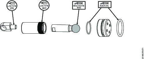
Lubrication Instructions
Lubricant Guide
Drive Components | Molykote 1000 |
Seals | Rocol Sapphire Aqua-Sil |
Fasteners | Loctite 243 |
Tapered Hydraulic Threads | Loctite 577 |
Lubrication
To keep the wrenches in good working condition, lubricate the drive components periodically between service intervals.
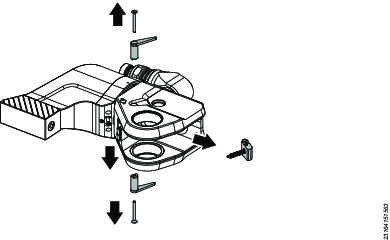
Disassembly before lubrication:
Remove the square drive.
Remove the access plugs [×2].
Remove the shroud screws [×4] and the shroud.
Remove the retaining clips [×2].
Remove the drive sleeves [×2].
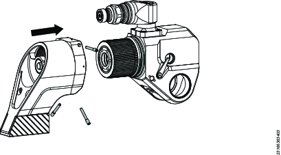
Position the drive pin in line with the access plug hole. Push the pin out of the housing to release the drive assembly.
Remove the drive assembly from the housing.
Do the following actions during lubrication maintenance:
Examine the drive pin for signs of wear or damage. Replace the pin if necessary.
Examine the edges of ratchet teeth for signs of damage. Replace the ratchet if necessary.
Examine the drive pawl teeth for signs of damage. Replace the drive pawl if necessary.
Examine the drive pawl springs for signs of damage. Replace the springs if necessary.
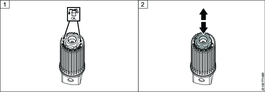
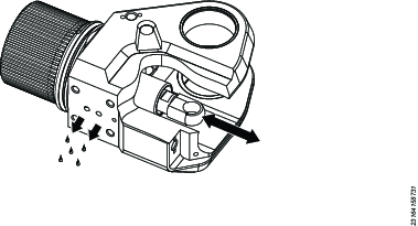
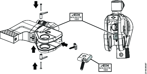
Lubricate the shaded areas with Molykote 1000.
Apply 2 drops of oil into the square drive and press the button several times to distribute the oil around the mechanism.
The procedure for assembly is the same as for disassembly, but backwards.
Dismantling/Assembling Instructions
Disassembling the Drive Mechanism
Remove the square drive.
Remove the access plugs [×2].
Remove the shroud screws [×4] and the shroud.
Oil in the drive mechanism indicates a possible seal failure.
Remove the retaining clips [×2].
Remove the drive sleeves [×2].
Position the drive pin in line with the access plug hole. Push the pin out of the housing to release the drive assembly.
Remove the drive assembly from the housing.
Removing the Reaction Pawl
Loosen and remove the disengagement lever screws.
Remove the disengagement levers.
Lower the reaction pawl and remove the pin from the housing.
Remove the reaction pawl and spring from the housing.
Removing the Reaction Arm
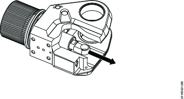
Loosen and remove the anchor retaining screws [×3].
Press the release button and slide the reaction arm sub-assembly off the wrench.
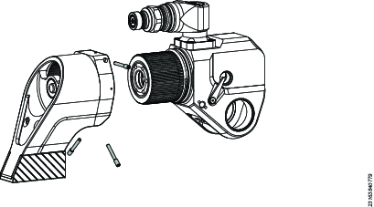
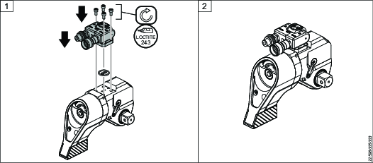
Removing the Swivel
Loosen the swivel retaining bolts.
Remove the swivel.
Removing the Endcap and Piston
Before you remove the endcap, drain the oil from the wrench.
Position the oil ports over a suitable container.
Pull the piston rod out until it stops.
Push the piston rod back.
The oil from the tool runs out through the ports.
Put the housing in a suitable vice to hold it safely.
Remove the endcap with the tools listed and a suitable hand torque wrench or breaker bar.
It can take considerable force to break loose the endcap threads. Apply axial force to the endcap tool to keep it engaged while breaking loose the threads.
Fully unscrew the threads and pull the end cap and piston assembly from the wrench housing.

Model | Endcap Tool |
|---|---|
TF01 | 4222 9062 87 |
TF03 | 4222 9062 96 |
TF05 | 4222 9062 99 |
TF08 | |
TF10 |
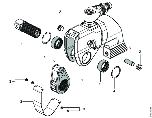
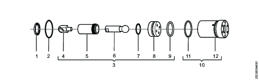
Disassembling the Piston
If no oil has leaked into the drive side of the wrench, it is not necessary to fully disassemble the piston rod sub assembly. Simply replace the outer piston seal [9].
Inspect the bore of the piston rod end [4]. If the piston rod end is in good condition, there is no need to remove it.
To fully disassemble:
Unscrew the piston rod end [4] from the piston rod [6].
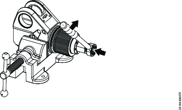
Clamp the piston sleeve [5] in a vice with the special vice grips.
Use the piston tool to unscrew the piston [8] from the piston sleeve [5].
Model | Piston Tool | Piston Sleeve Vice Grip |
|---|---|---|
TF01 | 4222906410 | 4222906393 |
TF03 | 4222906411 | 4222906394 |
TF05 | 4222906395 | |
TF08 | 4222906412 | 4222906396 |
TF10 | 4222906397 |
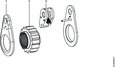
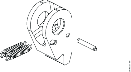
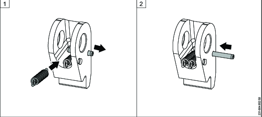
Disassembling the Drive
Remove one drive plate [1].
Remove the ratchet [2].
Remove the drive pawl and springs [3].
Inspect the parts for damage: look for cracks in the ratchet teeth root and damage to the edges of the teeth. If there is any damage, replace the part.
Disassembling the Drive Pawl
Remove the pin.
Remove the springs.
Inspect the parts for damage: look for cracks in the root of the teeth and damage to the driving edges. If there is any damage, replace the part.
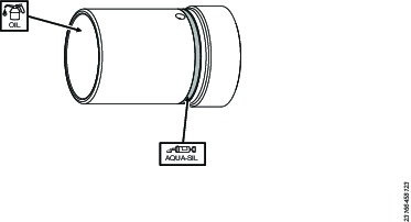
Assembling the Piston
Lubricate the shaded areas with Molykote 1000.
Install the seals in the grooves on the piston head; lubricate the seals with Aqua-Sil.
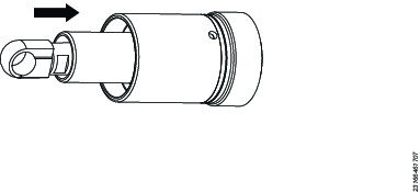
Insert the piston rod through the piston sleeve.
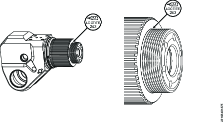
Apply Loctite 243 to the threads on the piston sleeve.
Screw the piston sleeve into the piston head.
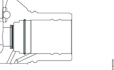
Clamp the piston sleeve in a vice with the special vice grips.
Use the piston tool to tighten the piston to the correct installation torque in the table below.
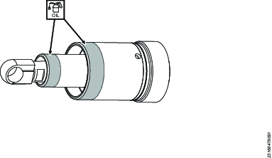
Apply Loctite 270 to the piston rod end and screw it into the piston rod. Fasten the piston rod end in a vice and tighten to the correct installation torque in the table below.
Model | Installation Torque (Nm) | Piston Tool | Piston Sleeve Vice Grip |
|---|---|---|---|
TF01 | 20 | 4222906410 | 4222906393 |
TF03 | 30 | 4222906411 | 4222906394 |
TF05 | 35 | 4222906395 | |
TF08 | 45 | 4222906412 | 4222906396 |
TF10 | 55 | 4222906397 |
Model | Installation Torque (Nm) | Wrench Size |
|---|---|---|
TF01 | 10 | 3/8 in. |
TF03 | 25 | 1/2 in. |
TF05 | 34 | 16 mm |
TF08 | 50 | 11/16 in. |
TF10 | 75 | 13/16 in. |
Assembling the Hydraulic Cylinder
Lubricate the O-ring with Aqua-Sil and place in the seal groove.
Apply a smear of hydraulic oil to the bore of the endcap.
Insert the piston assembly into the endcap; push the piston assembly to the bottom of the endcap bore.
Insert the U-cup seal and the O-ring into the housing seal grooves.
Apply Aqua-Sil to the housing seals. Apply a smear of hydraulic oil onto the outside diameter of the endcap sleeve and the piston sleeve.
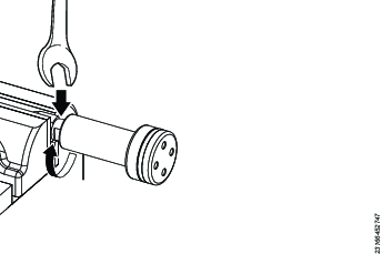
Insert the endcap and piston, then apply 1 drop of Loctite 243 to the first end cap thread.
Tighten the end cap with the end cap tool to the torque specified in the table.
Pull the piston rod out until it stops.
Install the swivel manifold. See section Assembling the Swivel Manifold.
Model | Installation Torque (Nm) | Endcap Tool |
|---|---|---|
TF01 | 122 | 4222 9062 87 |
TF03 | 122 | 4222 9062 96 |
TF05 | 143 | 4222 9062 99 |
TF08 | 163 | |
TF10 | 163 |
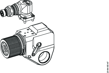
Assembling the Swivel Manifold
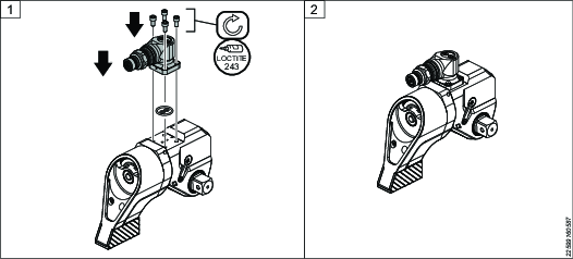
The Torcflex wrench can be fitted with 2 types of swivel manifold. Follow the instructions below to replace or change the manifold when needed.
Use Loctite 243 as thread locker to prevent loosening on assemblies.
Model | Hex Key (mm) | Torque (Nm) |
|---|---|---|
TF01 | 4 | 11 |
TF03–TF10 | 5 | 18 |
Installing a Co-axial Swivel Manifold
Installing a Twin-line Swivel Manifold
Filling Oil
Connect the wrench to a pump with a hose.
Press and release the Advance button [1] to start the pump.
The retract side of the hydraulic cylinder is automatically filled and pushes the piston to the starting position. Air from the advance side of the piston will be forced into the hose.
Press the Stop button [0] to stop the pump. Then press the button on the directional control valve to depressurize the retract line.
Disconnect the hose and purge the air from the hose, as follows:
For co-axial hoses: With the wrench disconnected, start the pump and stop it again after 10 seconds. This will cause oil to circulate between the advance and retract lines and will purge the air out of the hose.
For screw-to-connect hoses: screw the loose ends of the hoses together to form a loop. Start the pump and stop it again after 10 seconds. This will cause oil to circulate between the advance and retract lines and will purge the air out of the hose.
Reconnect the hose to the wrench.
Advance and retract the piston 10 times.
Stop the pump.
Disconnect the hose and repeat the air purge procedure.
Pressure Testing
Connect the wrench to the pump.
Press and release the Advance [1] button to start the pump. Wait for 10 seconds and look for any signs of oil leaks.
Press and hold the Advance button and pressurize the tool to 690 bar (10,000 psi). Hold for 10 seconds and look for any signs of oil leaks.
Release the button and pressurize again 3 times, look for any signs of oil leaks each time.
Assembling the Drive Pawl
Insert the pin partially.
Hook the springs over the pin.
Fully insert the pin.
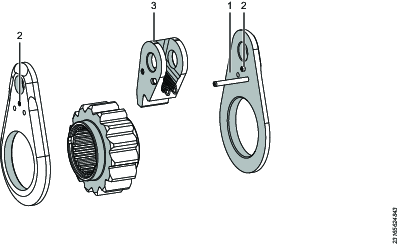
Assembling the Drive
Install the long spring pin [1] into one of the drive plates.
Insert the short spring pins [2] into both drive plates.
Lubricate the shaded areas with Molykote 1000.
Hook the drive pawl springs [4] over the long spring pin [1].
Insert the ratchet [5] into the drive plate bore.
Install the second drive plate [6] and push it into place.
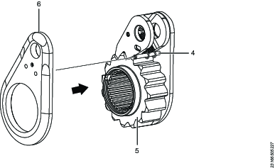
Assembling the Reaction Pawl
Lubricate the housing and the reaction pawl as shown with Molykote 1000.
Insert the reaction pawl spring through the hole in the housing. Secure with the split pin.
Push the reaction pawl into the slot in the housing and insert one of the disengagement levers.
Insert the tab on the disengagement lever into the slot on the reaction pawl.
Apply Loctite 243 to the screw and fasten the disengagement lever to the reaction pawl.
Install the second disengagement lever and screw in the same way on the other side of the housing.
Assembling the Reaction Arm
Lubricate the housing groove with Aqua-Sil.
Slide the reaction arm assembly onto the housing splines, in the orientation shown, until the retaining button clicks.
Install the long grub screws [×3].
Final Assembly of the Drive
Before inserting the drive components, make sure that the piston rod end is correctly oriented. The engraving "TOP" must be uppermost as shown.
Lubricate the shaded areas of the piston rod and the reaction pawl as shown.
Lubricate the shaded areas with Molykote 1000.
Insert the drive assembly [7] into the housing. Place the piston rod end within the drive pawl.
Position the drive pin hole in line with the access plug holes. Push the drive pin [6] through the housing and into the drive assembly [7].
Install the access plugs [2].
Push the reaction pawl levers upward, then align the ratchet bore with the housing bore.
Align the tabs on the first drive sleeve [5] tabs with the corresponding slots in the ratchet and push it into the housing. Install the retaining clip. Repeat on the other side.
Apply Loctite 243 on the shroud screws. Install the shroud and screws [3].
Insert the square drive [1] through the ratchet.
Rotate the lock button until it pops out. Pull the square drive to make sure that the installation is correct.
Testing the Assembly
Rotate the square drive and make sure that the drive pawl and reaction pawls move as expected.
Make sure that the reaction arm mechanism works as expected. See the section Setting the Reaction Arm.
Connect the wrench to a pump and hose.
Advance and retract the wrench; make sure that the square drive indexes forward with each cycle.
As a final test, calibrate the wrench to make sure that the torque output is as expected.
Troubleshooting
Troubleshooting
Symptom | Probable Cause | Required Action |
|---|---|---|
The wrench will not advance. |
|
|
The wrench will not retract. |
|
|
The wrench will not advance but gauge shows pressure. |
|
|
The wrench operates in reverse (screw-to connect couplings only). |
|
|
Wrench pressure will not build. |
|
|
Wrench operation is slow. |
|
|
The tool is locked on the application. |
|
|
The ratchet is not taking successive strokes. |
|
|
The ratchet jumps during advance stroke. |
|
|
No reading on the pressure gauge but the wrench is operating. |
|
|
Difficult to connect the hose to the wrench or pump. |
|
|
Oil is leaking from shroud. |
|
|
The swivel or coaxial coupling is hot. |
|
|
The coupling leaks oil after disconnection. |
|
|
The square drive button cannot be pressed. |
|
|
Recycling
Environmental Regulations
When a product has served its purpose it has to be recycled properly. Dismantle the product and recycle the components in accordance with local legislation.