ToolsNet 8 (8.21)
Software
Introduction
In this section, you can find the basic information about the product and also the formatting conventions used in the topics.
General Description
ToolsNet 8 is a data collection and process improvement software that is personalized to your needs, based on a reliable production data collection and aimed to provide simple production analysis. The software gives you the capability to continuously enhance your processes. It gives you full control resulting in less rework, higher quality and maximum uptime.
Features
Dashboard & adjustable widgets
Statistical analysis
Trace and reference trace analysis
Detailed tool and controller connection overview
NOK trend notification
Reports favorites management
Programs comparison
Data archiving
Benefits
Increased productivity and flexibility
Excellent user interface and customizable view per user
Reduced rework with retroactive analysis of traces and comparison with reference trace
Maximized uptime with automated notifications when trends occur
Reduced legal costs by safeguarding full data over the years
General Data Protection Regulation (GDPR)
This product offers the possibility to process personal identifiable information such as system user name, role and IP-address. The purpose of this processing capability could be to enhance quality control through traceability and proper access management.
If you decide to process personal data you need to be aware of and comply with relevant personal data protection rules, including, in the EU the GDPR as well as other applicable laws, directives and regulations. Atlas Copco can in no way be held liable for any use made by you of the product.
Revision History
Release Number | Revision Date | Revision Description |
|---|---|---|
item | item | none |
8.21 | 11/2021 | NEW content: UPDATED content:
|
8.20 | 07/2021 | NEW content:
UPDATED content:
|
8.19 | 03/2021 | NEW content:
UPDATED content:
|
8.18 | 10/2020 | No changes. New version 8.18 due to software release 8.18. |
8.17 | 06/2020 | NEW content:
UPDATED content:
|
8.16 | 03/2020 | NEW content:
|
8.15 | 12/2019 | NEW content:
|
8.14 | 07/2019 | NEW content:
|
8.13 | 02/2019 | NEW content:
|
8.12 | 01/2019 | From 8.12 the manual is a User Guide containing Installation, Configuration and Operation. NEW content:
|
Conventions
To enhance user understanding, certain formatting conventions are used throughout this document. The formatting conventions used are listed below.
Element | Notation | Description | Output |
|---|---|---|---|
General emphasis | In the Program workspace. | To make certain text elements stand out, or to highlight. | Text in Bold |
Graphical User Interface (GUI) items | Select the Function button. | Any reference to items found on screen in the GUI (for example, command buttons, icon names and field names). | Text in Bold |
Graphical User Interface (GUI) Path > | Generally, on the top of the GUI. | Navigation aid which keeps track of the location in the GUI. | For example: Controller > Program > Edit |
User input | Enter a Description for the program. | Any text input by the user. | Text in Bold |
File names | Enter a File Name for the export. | Files either exported from, or imported into the system. | Text in Bold Italic |
Variable and parameter names | Enter a Name for the export. | Variable and parameter names (not values). | Text in Italic |
Variable and parameter values | Enter a VALUE for the export. | Variable and parameter values. | Text in BOLD CAPS |
System output | Client.Domain.Models.ExportImportConfiguration | Any text output by the system. | Text in Monospace |
External links | Links to external sites that have information connected to the document or subject content. These could include:
| Selectable text to external sites | |
Internal documentation links |
If available, these links will be presented below the text. | Selectable text to internal content |
About the User Guide
The User Guide describes how to set up, configure and use ToolsNet. It is intended for anyone working with ToolsNet.
In the Search window on the top menu bar, search for Product Essentials Tutorials for checking the available video tutorials.
Each Product Essentials Tutorial will provide an overview of how to do a specific task with an Atlas Copco product. These tutorials are designed so that users can watch and follow along with their own equipment. The Product Essentials Tutorials are available online to ensure they are always available to users on-demand, and provide baseline knowledge needed to work with Atlas Copco products.
System Overview
Typical installation
Typical ToolsNet 8 installations are structured as shown in the image in Standalone installation; one server running ToolsNet 8 applications and one database server hosting the ToolsNet database.
The relationships between the separate modules in ToolsNet:
ToolsNet clients can access the server via a web browser.
The server also runs the various data collection services, which obtain the data from the controllers and save results on the database module.
The Internet Information Service displays the results on a webpage.
Check the image in Standalone installation to identify the different modules.
Standalone installation
In a standalone installation, both the server and the database module are installed and run on the same machine.
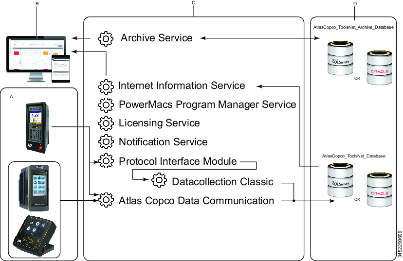
A | Controllers |
B | ToolsNet clients with webbrowser |
C | Server |
D | Database module |
Software GUI
ToolsNet 8 is a visually rich product providing first-class information.
The web interface for ToolsNet 8 is responsive and will automatically adjust to the screen size and resolution that you use, whereby the workspace content displayed and menu bar will change and adapt accordingly.
A | Top menu bar |
B | User settings and sign out. See Working with the User Account. |
C | Notification alerts. See Notifications. |
D | Left hand side menu bar - Tabs. See Menu Bar. |
E | Expand icon. See Menu Bar. |
F | Workspace - This area will display different content, depending on the selected view. |
Menu Bar
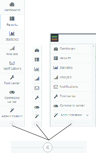
The tabs displayed on the left hand side menu bar in ToolsNet 8 are dependant on the license type acquired.
Icons | Description | Licensed Feature | Multi Tab within Workspace |
|---|---|---|---|
| Dashboard | Yes | No |
| Reports | Yes | Yes |
| Statistics | Yes | No |
| Analysis | Yes | Yes |
| Notifications | Yes | No |
| Tool Center | Yes | No |
| Command Center | Standard | No |
| Administration | Standard | No |


The appearance of the left hand side menu bar varies, depending on the web browser's zoom level, and the screen resolution.
Select the expand button to expand or minimize the menu.
Icons
The following table gives an overview of the icons and buttons available in the user interface for ToolsNet 8 :
Icon | Name | Description |
|---|---|---|
| Setting | Configure settings available |
| Sign Out | Sign out from ToolsNet 8 |
| Expand button | Opens up to view further information, or collapses to hide the information |
| Save | Save customized settings |
| Reload | Reload view of results |
| Export | Export results to Excel |
| Trace | View trace or magnified view of graph |
| Close | Close an application |
| Collapse | Collapse an application |
| Full screen | Expands to full screen |
| Full Screen | Minimizes the screen |


Installation and Upgrade
In this section, you can find information to help with the initial installation of the product, or upgrading from one version to another.
Installation Overview
For a correctly installed ToolsNet 8 working environment, follow the installation and configuration checklist below.
Infrastructure
Step | To do | Check | |
|---|---|---|---|
a For the RAM requirements, use the ToolsNet Fact Sheet that is obtainable from the Global Product Manager. b For the disk space calculations, use the ToolsNet Fact Sheet that is obtainable from the Global Product Manager. | |||
1 | Decide on server type (virtual or physical). | ░░ | |
2 | Decide on database location (local or remote). | ░░ | |
3 | Decide on database type (SQL Server or Oracle). | ░░ | |
4 | Decide on authentication type (none or Windows Active Directory). | ░░ | |
5 | Verify that amount of RAM on application server is sufficient.a | ░░ | |
7 | Verify that disk space for database is sufficient.b | ░░ | |
Installation
Step | To do | Check |
|---|---|---|
8 | Windows Server 2012R2 or higher installed on application server. | ░░ |
9 | Ports (according to User Guide) open on servers, see Before Installation. | ░░ |
10 | SQL Server 2014 or higher / Oracle 12c or higher. | ░░ |
11 | .Net Framework 4.8. | ░░ |
12 | Read through the Installation and Upgrade section of the ToolsNet 8 User Guide (latest version). | ░░ |
13 | Enable Message Queuing Services, see Configuring MSMQ. | ░░ |
14 | Enable Application Server and IIS roles according to the ToolsNet 8 User Guide (latest version), see Enabling Windows Integrated Authentication on IIS. | ░░ |
15 | Install the latest version of ACDC. | ░░ |
16 | Install the latest version of ToolsNet 8, see Installing ToolsNet 8. | ░░ |
17 | Register licenses. | ░░ |
18 | Start services. | ░░ |
Configuration
Step | To do | Check |
|---|---|---|
19 | Add first account (if no AD). | ░░ |
20 | Verify that user can log on correctly (if AD). | ░░ |
21 | Set up Delete Maintenance jobs in SQL Server Management Studio, see Scheduling Database Maintenance Jobs in SQL Server Enterprise and Standard Edition. | ░░ |
Archiving (if purchased)
Step | To do | Check |
|---|---|---|
22 | Create archive database with Archive Installer, see ToolsNet Archive Installer. | ░░ |
23 | Create link to archive database with Archive Installer, see ToolsNet Archive Installer. | ░░ |
24 | Set up archiving job in SQL Server Management Studio, see Scheduling Database Maintenance Jobs in SQL Server Enterprise and Standard Edition. | ░░ |
25 | Verify that DaysLimitForExport value is less than DaysToKeep value, see Scheduling Database Maintenance Jobs in SQL Server Enterprise and Standard Edition. | ░░ |
Supported Platforms
Depending on the version of the system and the licenses purchased, the system can provide the following services:
Result data collection from Power Focus 3000, Power Focus 4000, PowerMACS 3000, PowerMACS 4000, Power Focus 6000, the Scalable Quality Solution (SQS), and from other vendors through ToolsNet open protocol, TNDCP.
Trends, summaries and detailed data reporting in a web interface, based on results and events.
Statistical analysis of production data.
Alerts and administration of production events.
Tool service follow-ups for Power Focus 4000 and Power Focus 3000.
Compatibility
ToolsNet Version | Windows Server | SQL Server | Oracle | .Net | ACDC |
|---|---|---|---|---|---|
TN 8.20 | 2019, 2016 | 2019, 2016 | 18c, 12c | 4.8 | 2.1 |
TN 8.19 | 2019, 2016 | 2019, 2016 | 18c, 12c | 4.8 | 1.13 and 2.0 |
TN 8.18 | 2019, 2016 | 2019, 2016 | 18c, 12c | 4.8 | 1.12 |
TN 8.17 | 2019, 2016 | 2016 | 12c | 4.8 | 1.11 |
TN 8.16 | 2019, 2016 | 2016 | 12c | 4.8 | 1.9 |
TN 8.15 | 2016, 2012 R2 | 2016 | 12c | 4.6 | 1.7 |
TN 8.14 | 2016, 2012 R2 | 2016 | 12c | 4.6 | 1.5 |
TN 8.13 | 2016, 2012 R2 | 2016 | 12c | 4.6 |
|
TN 8.12 | 2016, 2012 R2 | 2016 | 12c | 4.6 |
|
For help with the installation of the software, refer to the official webpages of the respective software providers.
For help with the installation of the software, see the release notes for the respective versions of the database.
Oracle installations must be performed by an expert and only when there’s an Oracle DBA present. Refer to Installing Oracle for further instructions.
Before installation, make sure that SQL Server Agent is activated. This is done in Windows services.
For help with the installation of the software, refer to the official webpages of the respective software providers.
ToolsNet 8 does not support SQL Express.
Before Installation
The following preparations are needed prior to installation of ToolsNet 8:
Make sure that the computers that are to run ToolsNet 8 comply with the hardware and software requirements.
Make sure that the system firewall is OFF, or open the ports.
Make sure that AC DataCommunication is installed.
If ToolsNet 4000 is installed on the server, perform an upgrade.
Port No | Protocol | Firewall | Collection | Description | Conf.able |
|---|---|---|---|---|---|
4545 | Atlas Copco Data Communication Service | ToolsNet Open Protocol | |||
4680 | TCP | Internal/External | TNServer.exe | Used for TDD (Tools Data Distribution) and TNEmail (TCP communication) with TNServer | No |
9010, 9011 | TCP | External | Atlas Copco Data Communication Service | PowerFocus 4000 | Yes |
9012,9013 | Atlas Copco Data Communication Service | PowerMacs protocol version 3 | Yes | ||
9014,9015 | Atlas Copco Data Communication Service | ToolsNet Open Protocol | Yes | ||
9016 | PX2 | Atlas Copco Data Communication Service | PF6000 | ||
6700 | Atlas Copco Data Communication Service | ToolsNet Data Collection Protocol | Yes | ||
6555 | TCP | External | TNServer.exe | Used for PowerFocus 2000 TCP communication with TNServer | No |
6543 | TCP | External | TNServer.exe | Used for PowerFocus 3000 TCP communication with TNServer, protocol 1 (PF W3 and W5) | No |
6572 | TCP | External | TNServer.exe | Used for PowerFocus 3000/4000 TCP communication with TNServer, protocol 2 | No |
6544 | TCP | External | TNServer.exe | Used for PowerMACS TCP communication with TNServer, port 1 (PM classic W2) | No |
6574 | TCP | External | TNServer.exe | Used for PowerMACS TCP communication with TNServer, port 2 | Yes |
6576 | TCP | External | TNServer.exe | Used for OpenProtocol TCP communication with TNServer, port 2 | Yes |
89 | TCP | Internal | TNServer.exe | Used for ToolsNet Server communication and settings. By browsing locally to http://127.0.0.1:89 you can access the TNServer settings page. | No |
6570 | TCP | External | PIM.exe | Used for PowerFocus TCP communication with PIM | Yes |
6571 | TCP | Internal | PIM.exe | Used for HTTP access to the PIM Settings page http://127.0.0.1:6571 | No |
6573 | TCP | External | PIM.exe | Used by PowerMACS systems for TCP communication with PIM | Yes |
6575 | TCP | External | PIM.exe | Used by controllers for TCP communication via OpenProtocol to PIM | Yes |
6593 | TCP | Internal/External | ACTLicenseServer.exe | Used by TNServer for TCP communication with the New License Server | No |
6594 | TCP | Internal/External | ACTLicenseServer.exe | Used by License client application for TCP communication with the New License Server | No |
6594 | TCP | Internal/External | ACTLicenseServer.exe | Used by ADC for TCP communication with the New License Server | No |
6595 | TCP | Internal/External | ACTLicenseServer.exe | Used by Open Protocol controllers or system components for TCP communication with the New License Server | No |
7110 | Atlas Copco Data Communication Service | WebAPI port used by ToolsNet web | No | ||
7102 | Notification Service | WebAPI port used by ToolsNet web | No | ||
7101 | Archive Service | WebAPI port used by ToolsNet web | No | ||
9991 | TCP | Internal | LicenseCheckerService | No longer used in ToolsNet 7.8 and above | No |
9993 | TCP | Internal | PMProgramManagerProxy | Used to see PowerMacs program details. | No |
Read the sections about server configuration for the intended server use. Always make sure that your database server is installed, set up properly, and running.
Hard drives and data files
Contact the database administrator to determine the following settings.
Check that there is enough free hard drive space for Production data.
Decide which hard drive volume and folder should be used for Production data.
These values are not set at this stage.
The SQL Server transaction log file grows when delete maintenance is running. This log file is truncated when the database is backed up. The DBA needs to have a strategy for keeping a reasonable log file size.
Also see how to set up the connection to Oracle database server and TNSNAMES.
Path Overview for a Default Installation
The tables below list the paths to important applications and files for a default installation of ToolsNet 8.
| Root folder for Atlas Copco applications |
|---|---|
| License server, logs for license server, registration application. |
| Application for sending out notifications related to controller events. |
| ToolsNet 8 web application. |
| Data collection service for Power Focus 4000, PowerMACS 4000 and open protocol. |
| Application folder for the service manager. |
| Used for AC DataCommunication service. |
| Application for Archive events. |
| Root folder for application settings and application log files |
|---|---|
| Application log files. |
| Settings for the license server. |
| Settings for the notification service. |
| Settings for the ToolsNet web application. |
| Settings that are common for different parts of the application. |
| Installation scripts for the ToolsNet database. |
| Settings that are common for different parts of ACDC. |
Installing ToolsNet 8
In this section installation of ToolsNet 8 is described.
For a correctly installed working environment, follow the installation and configuration checklist see Installation Overview.
Complete Installation
The Complete installation installs all ToolsNet components.
Database installations should be done by an expert and only when a DBA is present.
Double-click AtlasCopco ToolsNet IC 8.XX.XXXXX.msi.
In the InstallShield Wizard, select Next.
In the License Agreement dialog box, read the License Agreement. If agreed, select the option I accept the terms in the license agreement, and then select Next.
In the Setup Type dialog box, select Complete, and then select Next.
In the Ready to Install the Program dialog box, select Install, and wait for the InstallShield Wizard to finish the installation.
The setup must update files or services that cannot be updated while the system is running. If you choose to continue, a reboot will be required to complete the setup.
Select OK to close running applications.
The ToolsNet Installation Configurator opens.
If required, select CONFIRM to restore app settings from the previous ToolsNet installation. Otherwise, select CANCEL.
Select Finish to exit the wizard and to continue with the ToolsNet Installation Configurator.
In the ToolsNet tab, review the application settings and the authentication settings. If required, adjust them and select SAVE.

If the database is hosted on the computer running the installation, set the ACDC IP Address in Application settings to
127.0.0.1.If the ACDC version is too old, a warning is displayed:
Data communication service could not be reached or have a too low version (found version is: X.X.X and required version is: X.X.XXXXX) Do you want to continue the installation anyway? YES or NO.
When changing the Authentication method in Authentication settings to Windows, a network connection to a domain is required and the Admin group needs to be entered.
In the Database tab, review the On Premise Configuration. Perform the necessary changes and select SAVE.
For SQL Server
In the Server Data Source field, type the IP address, or the computer name for the database, and then select SAVE.
For Oracle
In the Server Data Source field, type the TNS data for the database, and then select SAVE.
If the database is hosted on the computer running the installation, set the IP address to
127.0.0.1.Only select Enable TLS 1.2 Support in connection with the Data Collection Classic service.
If the provider Microsoft OLE DB Driver for SQL Server (MSOLEDBSQL) is not installed, the Data Collection Classic will not work.
As to the Credentials for user in order to create the database
Enter the user name and password on the SQL Server or the Oracle server, and then select SAVE.
Make sure that the user has permission to create a database, users and database jobs.
The user name entered is only used for the installation. The installer creates new users with limited access only to the ToolsNet database and the ToolsNet related database jobs.
To validate the user credentials, select TEST CONNECTION. The test connection will attempt to access the database using the credentials provided. If the test connection fails, make sure that the user is set up properly on the database server.
TEST CONNECTION only works for a SQL database.
Select the Database Installer tab and select RUN SCRIPTS.
Wait until the Database Installer has finished and select OK.
Obtaining a ToolsNet Web Address
To start ToolsNet 8 it is necessary to obtain the web address to the ToolsNet system. This address is normally provided by a ToolsNet super user.
http://<server name>/ToolsNet
The <server name> differs between installations. The structure of the web address can vary between plants, depending on how it is installed by the IT staff.
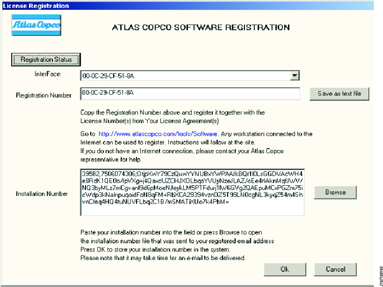
Registering the Software
Atlas Copco Tools AB – Licensing (ACT - Licensing) is installed on the same server as the ToolsNet application.
The installation number is required to run the system.
Open the Installation Number File that was sent to the Registered email address.
Note that it may take time for the email to be delivered.
Enter the Installation Number for the product in the Installation Number box, or select Browse and then select the Installation Number File.
Select Ok if the installation number is available.
ACT - Licensing has a known issue with HP servers with multiple network cards working in team. In this environment, ACT - Licensing fails to retrieve a MAC address and signals license failure. The workaround is to install ACT - Licensing on a different server.
Select Registration Status to confirm that the installation number is valid.
The License Status window lists the product options enabled in the system.
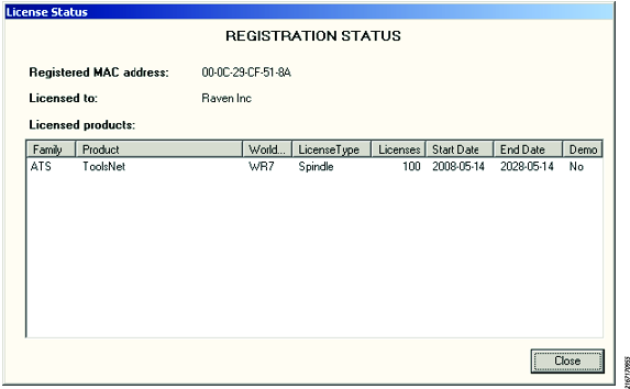
Select Close, then select Ok to close the License Registration window.
Select Finish to exit the wizard.
Viewing the Status of the ToolsNet 8 Installation
In a web browser, enter the URL
<IP address>/ToolsNetIP address is the IP address of the ToolsNet 8 Application Server.
Select Command Center to see all licensed features presented in the License Status dialog box.
Configuration
In this section, you can find detailed information about how to create, modify, and verify product settings.
Working with the ToolsNet Installation Configurator
The ToolsNet Installation Configurator is used to review and, if needed, to change the configuration settings of the ToolsNet 8 installation. The ToolsNet Installation Configurator is opened automatically during the installation of ToolsNet 8. It can also be opened from the desktop or the Start menu.
The ToolsNet Installation Configurator has the following tabs:
The ToolsNet tab, containing the application and the authentication settings
The Database tab, containing the database settings
The Database Installer tab, containing an overview of the database scripts
Open ToolsNet Installation Configurator from the desktop or the Start menu.
In the ToolsNet tab, review the application settings and the authentication settings. If required, adjust them and select SAVE.
If the database is hosted on the computer running the installation, set the ACDC IP Address in Application settings to
127.0.0.1.If the ACDC version is too old, a warning is displayed:
Data communication service could not be reached or have a too low version (found version is: X.X.X and required version is: X.X.XXXXX) Do you want to continue the installation anyway? YES or NO.
When changing the Authentication method in Authentication settings to Windows, a network connection to a domain is required and the Admin group needs to be entered.
In the Database tab, review the On Premise Configuration. Perform the necessary changes and select SAVE.
For SQL Server
In the Server Data Source field, type the IP address, or the computer name for the database, and then select SAVE.
For Oracle
In the Server Data Source field, type the TNS data for the database, and then select SAVE.
If the database is hosted on the computer running the installation, set the IP address to
127.0.0.1.Only select Enable TLS 1.2 Support in connection with the Data Collection Classic service.
If the provider Microsoft OLE DB Driver for SQL Server (MSOLEDBSQL) is not installed, the Data Collection Classic will not work.
As to the Credentials for user in order to create the database
Enter the user name and password on the SQL Server or the Oracle server, and then select SAVE.
Make sure that the user has permission to create a database, users and database jobs.
The user name entered is only used for the installation. The installer creates new users with limited access only to the ToolsNet database and the ToolsNet related database jobs.
To validate the user credentials, select TEST CONNECTION. The test connection will attempt to access the database using the credentials provided. If the test connection fails, make sure that the user is set up properly on the database server.
TEST CONNECTION only works for a SQL database.
Select the Database Installer tab and select RUN SCRIPTS.
Wait until the Database Installer has finished and select OK.
Working with the Server
The server runs the data collection services Data Collection Classic and Atlas Copco Data Collection (ACDC), which obtain the data from the controllers and save the results on the Database module. This section explain how to operate the server, and how to modify the server configuration.
- Stopping the Data Collection Services
- Restarting the Data Collection Services
- Viewing Information About Server Connection Failure
- Editing the Password for Data Collection Classic
- Configuring Windows Integrated Authentication
- Encrypting the Common Configuration Password
- Modifying the ToolsNet 8 Server Settings
- Configuring Windows Server 2019 for ToolsNet 8
- Configuring Windows Server 2016 for ToolsNet 8
- Configuring Windows Server 2012 R2 for ToolsNet 8
- Configuring MSMQ
Stopping the Data Collection Services
In the event of a connection failure between a Power Focus or PowerMACS system and the collection services Data Collection Classic or Atlas Copco Data Collection service (ACDC), data will be buffered in the controller. The buffered data will be retrieved by the data collection module as soon as a network connection is re-established.
The buffer size available depends on the controller type and current configuration. Refer to the manual for the controller and check memory settings/controller configuration, to determine the buffer size.
Internet Information Services do not normally need to be ended. If this service is ended, it will affect other web applications that do not belong to the ToolsNet system.
Start the ToolsNet Service Manager.
Stop the following services by selecting Stop:
Data Collection Classic
Atlas Copco Data Collection service (ACDC)
Protocol Interface Module
Notification Service
License Server
Data Communication Service
Restarting the Data Collection Services
The server needs to be restarted after installation. After the restart, the ToolsNet 8 services should start automatically. ToolsNet Service Manager can then be used to verify that the required services are running.
Start the ToolsNet Service Manager.
Make sure that the following services are running (the text Running! will be shown in the box for the service when running):
License Server
Data Collection Classic (older generation controllers)
Atlas Copco Data Collection service (Power Focus 6000)
Protocol Interface Module
Internet Information Services
Data Communication Service (ToolsNet data collection protocol)
For the Alerts license package, the following service should also be started:
Notification Service
For Archive license package, the following service should also be started:
Archive Service
If a service is not running, select Start.
Viewing Information About Server Connection Failure
As soon as a database connection is lost, the ToolsNet 8 data collection service will start buffering results and graphs to the hard disk drive. This feature also protects data if the network connection is lost between the ToolsNet 8 server and the database server.
All results that are collected during this time are stored in temporary files with the extension .que for the data collection classic and as Microsoft message queue (MSMQ) files for the data collection service.
For the data collection classic there is one queue for each controller type:
pf.que for PowerFocus 3000 and Power Focus 4000
pm.que for PowerMACS
op.que for PowerFocus 2000 and other devices reporting with ToolsNet open protocol
The default path to the .que files is C:\Program Files (x86)\Atlas Copco\bin.
Information about database connection failure will be logged in the TNserver.log file which is found in the same folder as the queue files.
For the data collection service there will be one individual MSMQ file for each of the controllers reporting to ToolsNet 8.
The queue files can be viewed using the Computer Management application.
Start the application Computer Management.
In the Computer Management window, select Services and Applications, then Message Queuing, followed by Private Queues.
The log files for the data collection service are located in c:\ProgramData\Atlas Copco\Logs\DataCollectionService\. One log file will be created for each day.
As soon as SQL Server is started, controller data will be retrieved from the .que files and from the MSMQ files and stored in the database.
It may take time to retrieve all data if the database has been stopped for a long time.
Editing the Password for Data Collection Classic
To edit the password for Data Collection Classic, use the Windows registry editor.
Select the Start button in the taskbar, type regedit in the Search programs and files box, and then select regedit.exe.
In the Registry Editor, select Computer > HKEY_LOCAL_MACHINE > SOFTWARE > Wow6432Node > Atlas Copco Tools AB > Common
Select the registry key ConnectionStrings, select the value DataCollection, and then select Modify...
In the Edit String dialog box, enter the password in the Value data: box.
Example:
127.0.0.1;User ID=ToolsNetUser;Password=MyNewPassword;Persist...Select OK.
Configuring Windows Integrated Authentication
When configuring Windows Integrated Authentication, the following prerequisites must be checked:
The ToolsNet Server is connected to Active Directory (AD).
An AD security group is used as a ToolsNet administrator Group.
If Use Windows accounts was selected during the ToolsNet 8 installation, see Installing ToolsNet 8, Complete Installation.
Enabling Windows Integrated Authentication on IIS
Windows Authentication security features must be installed.
Select Start, and then select Internet Information Services (IIS) Manager.
Select the server for ToolsNet 8.
Expand Sites, and then expand Default Web Site.
Select ToolsNet, select Windows Authentication, and then select Enable in the drop-down list.
Adding the ToolsNet URL to Trusted Sites
In the web reader, open the selections for Trusted Sites.
Enter the URL for the ToolsNet website. The URL is in the format
<IP address>/ToolsNetwhere<IP address>is the IP address of the ToolsNet Server.Select Add.
Activating Automatic Logon in your Web Browser
In the web browser, open the selections for Trusted Sites.
Select Custom Level....
Scroll down to User Authentication in the Settings list.
Select Automatic logon with current user name and password.
Select OK and then select Yes in the Warning dialog box.
Setting the Administration Role
The administration role is set during installation but can be changed manually in the web.config file.
Navigate to C:\Program Files (x86)\Atlas Copco\ToolsNet. If the installation path was changed from default during the installation of ToolsNet 8, navigate to that path instead.
Open
web.configin a text editor, for example Notepad.The default path is C:\Program Files (x86)\Atlas Copco\ToolsNet. If the default path was changed during installation of ToolsNet 8, use that path instead.
In the appSettings element, add the following line:
<add key="Roles.Administrator" value="SID" />Replace SID with an S-X-X-X, where X is an integer.
In the system.web element, add the following line:
<authentication mode="Windows" />Save the file.
Modifying Roles
As a member of the administration group, you can tie roles to each center in ToolsNet, when logged into the ToolsNet web client.
In Internet Explorer, Enter the URL
<IP address>/ToolsNetinto the URL bar (replace<IP address>with the IP address of the ToolsNet Server).Select Administration, and then select Group administration.
Select the Edit button. Change the SID to change the group that is tied to the center.
Encrypting the Common Configuration Password
It is possible to encrypt the passwords so that they are not visible in the Common Configuration file. The password for the ToolsNet server stored in the registry cannot be encrypted.
Only the password in common configuration can be encrypted
Open the ToolsNet Service Manager.
Stop the Data Collection Service.
In a web browser, enter the URL
http://<IP number>/toolsnet/administration/encryption.<IP number> is the IP address to the ToolsNet 8 Server, for example
127.0.0.1for localhost.Type the password in the Text to encrypt box, and then select Encrypt.
Copy the shown encrypted password.
Open the ToolNetCommon file (C:\ProgramData\Atlas Copco\ToolsNetCommon) in a text editor, for example, Notepad.
Paste the encrypted password in the <Password> field.
<ConnectionStrings><clear/><add name="ToolsNetServer"....User ID=ToolsNetUser;Password=<Password>==;<add name="ToolsNet"....User ID=ToolsNetUser;Password=<Password>==;</ConnectionStrings>Change encryption to “true”.
<appSettings><add key="ConnectionString.IsEncrypted" value="true"</appSettings>In the ToolsNet Service Manager, restart the Internet Information Services (IIS) and Data Collection Service services.
Modifying the ToolsNet 8 Server Settings
The server registry settings can be modified for the Data Collection Classic service by using the ToolsNet server settings web interface. Access the web interface using theToolsNet Service Manager or a web browser. Make the changes and select Store to save them.
Accessing the ToolsNet Server Settings
Modifications and setting in ToolsNet 8 can be made in two ways, settings made in the server settings web interface or by the Service Manager on the ToolsNet server.
For security reasons it is not possible to access the ToolsNet server settings web interface from any other computer or device.
Enter the ToolsNet 8 URL into a web browser, on the server where the ToolsNet application is running.
In the web interface, select the Show advanced options check box, and then select Store settings.
The mode is set to basic by default, even if advanced options have been shown previously.
Start the ToolsNet Service Manager.
In the Data Collection Classic dialog window, select the Tool icon located in the Data Collection Classic panel.
Registry Settings - General
The Registry settings - general are presented in the table below.
Setting/Button | Function | Comment |
|---|---|---|
Show advanced options | Show/Hide advanced setting options. | Check/clear the box and press the button Store settings to show/hide advanced options. |
License IP | IP address for License server. | |
Lost tightening timer Power Focus 3000 | Set up this value if Power Focus has speed problems when communicating. | Default should be 0. |
Use MAC address | Prompts ToolsNet Server to use MAC address as identifier for Power Focus units, instead of using the IP address of the unit. | Used for cases when NAT (Network address translation) devices are used in between Power Focus unit and ToolsNet. NOTE ! The web reports will show MAC address instead of IP address if this option is used. |
Database Connectivity
The settings for database connectivity are presented in the table below.
Setting/Button | Function | Comment |
|---|---|---|
Connected/Disconnected | Shows current database connection status. | Use F5 or refresh in the browser to ensure that the latest status is presented. |
Queue path | Enter path to the buffer files that store data during lost database connection. | |
SMTP host | IP address of the mail server to which alert message is sent in case of database connection failure. | Not in use in ToolsNet 8 |
Sender email | Email address that appears as ‘From’ address, in the email that was sent. | Not in use in ToolsNet 8 |
Notification receivers | Email addresses of the person(s) that should be notified if the database connection is lost. | Not in use in ToolsNet 8 |
Time Server Settings
The settings for the time server are presented in the table below.
Setting/Button | Function | Comment |
|---|---|---|
Frequency | Set frequency for time update from ToolsNet Server to connected Power Focus 3000 controllers. | |
Time protocol | Time synchronization messages can be sent either as multicast messages, which are not routable, or as UDP messages, which can pass routers. | Check the box for UDP. Clear the box for multicast. |
Log Settings
The log settings are presented in the table below.
Setting/Button | Function | Comment |
|---|---|---|
Use extended logging | Affects the information provided in the | Note that extended logging consumes resources. This setting should be cleared during normal production. |
Additional Settings
Additional settings are presented in the table below.
Setting/Button | Function | Comment |
|---|---|---|
System > Connections > Last event > Messages | The number of messages in queue should be low. An increasing number of messages in queue over a longer period of time indicates that the ToolsNet Server has problems receiving and storing information in the database with the current data load. | This value can increase for some time when ToolsNet Servers recover old data from controllers. |
Connected controllers | The IP address of each controller that is connected to the data collection service. | This information can be used to verify that controllers are connected to the ToolsNet Server. This list can show the same controller IP address multiple times, if the connection between the controller and ToolsNet Server was lost and then re-established. Lost connections are cleared every 10 minutes. To update the information about connected controllers, press the refresh button on the browser. |
User Accessibility
If ToolsNet 8 is set up with a connection to Active Directory, the user will have access to the parts of ToolsNet that are connected to the specific ToolsNet user group.
If no authentication is configured for ToolsNet the user can set up a new user authentication. The new user will be stored in ToolsNet. If the user's browser or computer changes, the user can select the stored authentication.
Configuring Windows Server 2019 for ToolsNet 8
Certain requirements apply to the installation of a Windows Server 2019. To configure the installation of ToolsNet 8 on a Windows Server 2019, complete the following.
On the menu bar, select
 to start the Server Manager.
On the Server Manager > Dashboard, select Add roles and features.
In the Select installation type dialog box, select Role-based or feature-based installation, and then select Next.
In the Select destination server dialog box, select Select a server from the server pool, and then select Next.
In the Select server roles selection box, expand Application Server (Installed) and select the check box for Web Server (IIS). select Next.
In the Select features selection box, select the check box for NET Framework 3.5, and then select Next.
In the Web Server Role (IIS) information box, read the information, and then select Next.
In the Select role services selection box, select the check boxes of the following:
Common HTTP Features
Health and Diagnostics
Performance
Security, Request Filtering
Security, Basic Authentication
Application Development, NET Extensibility 4.8
Application Development, Application Initialization
Application Development, ASP
Application Development, ASP.NET 4.8
Application Development, CGI
Application Development, ISAPI Extensions
Application Development, ISAPI Filters
Application Development, WebSocket protocol
Management Tools
Select Next.
In the Confirm installation selection information box, confirm the selections, and then select Install.
Configuring Windows Server 2016 for ToolsNet 8
Installation of a Windows Server 2016 has certain requirements. To configure the installation of ToolsNet 8 on a Windows Server 2016, complete the following.
On the menu bar, select
to start the Server Manager.On the Server Manager > Dashboard, select Add roles and features.
In the Select installation type dialog box, select Role-based or feature-based installation, and then select Next.
In the Select destination server dialog box, select Select a server from the server pool, and then select Next.
In the Select server roles selection box, expand Application Server (Installed) and select the check box for Web Server (IIS). select Next.
In the Select features selection box, select the check box for NET Framework 3.5, and then select Next.
In the Web Server Role (IIS) information box, read the information, and then select Next.
In the Select role services selection box, select the check boxes of the following:
Common HTTP Features
Health and Diagnostics
Performance
Security, Request Filtering
Security, Basic Authentication
Application Development, NET Extensibility 4.8
Application Development, Application Initialization
Application Development, ASP
Application Development, ASP.NET 4.8
Application Development, CGI
Application Development, ISAPI Extensions
Application Development, ISAPI Filters
Application Development, WebSocket protocol
Management Tools
Select Next.
In the Confirm installation selection information box, confirm the selections, and then select Install.
Configuring Windows Server 2012 R2 for ToolsNet 8
Installation of a Windows Server 2012 R2 has certain requirements. To configure the installation of ToolsNet 8 on a Windows Server 2012 R2, complete the following.
On the menu bar, select
to start the Server Manager.On the Server Manager > Dashboard, select Add roles and features.
In the Select installation type dialog box, select Role-based or feature-based installation, and then select Next.
In the Select destination server dialog box, select Select a server from the server pool, and then select Next.
In the Select server roles selection box, expand Application Server (Installed) and select the check box for Web Server (IIS). select Next.
In the Select features selection box, select the check box for NET Framework 3.5, and then select Next.
In the Web Server Role (IIS) information box, read the information, and then select Next.
In the Select role services selection box, select the check boxes of the following:
Common HTTP Features
Health and Diagnostics
Performance
Security, Request Filtering
Security, Basic Authentication
Application Development, NET Extensibility 4.8
Application Development, Application Initialization
Application Development, ASP
Application Development, ASP.NET 4.8
Application Development, CGI
Application Development, ISAPI Extensions
Application Development, ISAPI Filters
Application Development, WebSocket protocol
Management Tools
Select Next.
In the Confirm installation selection information box, confirm the selections, and then select Install.
Configuring MSMQ
MSMQ (Microsoft Message Queuing) is essentially a messaging protocol that allows applications running on separate servers/processes to communicate in a failsafe manner. A queue is a temporary storage location from which messages can be sent and received reliably, as and when conditions permit. Depending on plant size and/or production pace, it is recommended to increase the message storage size of the MSMQ from 1 GB (default). If the message storage is full, then data can be lost. It is recommended to remove or increase the limit.
List of the applications that must be installed:
Message Queuing MSMQ
On the menu bar, select
to start the Server Manager.On the Server Manager, Dashboard, select Next.
In the Select installation type dialog box, select Next.
In the Select destination server dialog box, select Next.
In the Select server roles, select Next.
In the Select features selection box, select the Message Queuing Services check box, and then select Next.
Select Next.
In the Confirm installation selection information box, confirm the selections, and then select Install.
Working with the Database
In order to keep the Atlas Copco Data Communication database up and running with good performance and reliability, the following maintenance activities are recommended:
Make regular backups of the database to secure the data in case of hardware failure and to keep the transaction log from growing in size.
Rebuild and reorganize the indexes in the database regularly, to keep the transactions and searches fast and optimized.
Delete old results that are no longer needed. This reduces the required disk space and improves report creation speed. After a Delete maintenance job it is also recommended to reorganize the indexes.
To run the maintenance job, setup and start the job scheduler manager for required database type.

A | Linked Server | B | Archiving Job |
C | Atlas Copco Data Communication DB | D | Table: dbo.ArchiveTargets |
E | Database Server | F | Archive db example: Period 1 |
G | Archive db example: Period 2 | H | Atlas Copco Data Communication Archive Database |
I | Archiving Service | J | Atlas Copco Data Communication Application Server |
Default Database Name
Depending on the database type that is chosen, the installation package creates a Default Database Name. The installation adds table spaces and required users on either the SQL Server or on Oracle.
Default Database Name for SQL Server | Default Database Name for Oracle | Purpose |
|---|---|---|
AtlasCopco_ToolsNet_Database | AtlasCopco_ToolsNet |
|
For Oracle, a user is created as a schema placeholder for table views and stored procedures for both databases.
Upgrading and Migrating the Database
In this section Upgrading and Migrating of the Database is described.
For a correctly installed working environment, follow the installation and configuration checklist, see Installation Overview.
Upgrading and Migrating the ToolsNet 8 Database by Script
This script will upgrade the database from ToolsNet 4000 - ToolsNet 8.2 to ToolsNet 8.10 and run the migration scripts. For ToolsNet 8.3 to ToolsNet 8.9 there is no need to run this script.
Unzip TN8UpgradeAndMigration.zip to the TN8UpgradeAndMigration folder.
Open the TN8UpgradeAndMigration folder.
Run the UpgradeAndMigrateTN.ps1 script, with administrative rights using Windows PowerShell.
With administrative rights, enter Database Login and Password: in the input fields, and then press Enter.
Select Database Type [O] Oracle, [M] MSSQL (default). For Help select [?], and press Enter.
Enter Server IP/TNSNAMES Alias:, and press Enter.
Enter Database file location:, and press Enter.
Migration can be a slow process depending on the size of the database.
Database Migration after Upgrading (Microsoft SQL) Manually
Database migration was introduced in ToolsNet 8.3. When upgrading from a lower version than ToolsNet 8.3, consider the following:
To finalize the migration it is required to run migration scripts after the upgrade, using Microsoft SQL Server Management Studio or similar.
The changes affect the database and change how the application stores traces, units, job results, program parameters and result parameters.
Migration using script
After an upgrade, the migration files are found in the following specified folders. Install the scripts in the following order, using Microsoft SQL Server Management Studio.
Go to C:\ProgramData\Atlas Copco\ToolsNetDatabase\Database scripts\Sql Server on the ToolsNet server.
Start Microsoft SQL Server Management Studio.
Open the MigrateToCommonGraph folder.
Drag the following files into Microsoft SQL Server Management Studio.
70_MigrateToCommonGraph.sql.
71_MigrateToCommonGraph_ManageFKandIX.sql.
In Microsoft SQL Server Management Studio, use the search and replace function to change the database name.
Execute the sql. script.
Install the scripts in the correct order.
Open the MigrateToGraphExtraInformation folder.
Only required if the database contains PF6-series data.
Drag the following files into Microsoft SQL Server Management Studio.
76_MigrateToGraphExtraInformation.sql.
72_MigrateToResultExtraInformation.sql .
78_MigrateProgramSetProgramNumber.sql.
In Microsoft SQL Server Management Studio, use the search and replace function to change the database name.
Execute the sql. script.
Install the scripts in the correct order.
Open the MigrateToResultToJobResult folder.
Drag the following files into Microsoft SQL Server Management Studio.
73_MigrateToResultToJobResult.sql.
74_MigrateToResultToJobResult_ManageFKandIX.sql.
In Microsoft SQL Server Management Studio, use the search and replace function to change the database name.
Execute the sql. script.
Database Migration after Upgrading (Oracle) Manually
Database migration was introduced in ToolsNet 8.3. When upgrading from a lower version than ToolsNet 8.3 consider the following:
To finalize the migration it is required to run migration scripts after the upgrade using Oracle SQL Developer or similar.
The changes affect the database and change how the application stores traces, units, job results, program parameters and result parameters.
After an upgrade, the migration files are found in the following specified folders. Install the scripts using Oracle SQL Developer in the following order.
Go to C:\ProgramData\Atlas Copco\ToolsNetDatabase\Database scripts\Oracle on the ToolsNet server.
Start Oracle SQL Developer.
Open the folder MigrateToCommonGraph.
Drag the following files in to Oracle SQL Developer.
70_MigrateToCommonGraph.sql.
71_MigrateToCommonGraph_ManageFKandIX.sql.
In Oracle SQL Developer, use the search and replace function to change the database name.
Run the sql. script using the play button.
Install the scripts in the correct order.
Open the folder MigrateToGraphExtraInformation.
Only required if the database contains PF6-series data.
Drag the following files in to Oracle SQL Developer.
76_MigrateToGraphExtraInformation.sql.
72_MigrateToResultExtraInformation.sql .
78_MigrateProgramSetProgramNumber.sql.
In Oracle SQL Developer, use the search and replace function to change the database name.
Run the sql. script using the play button.
Install the scripts in the correct order.
Open the folder MigrateToResultToJobResult.
Drag the following files in to Oracle SQL Developer.
73_MigrateToResultToJobResult.sql.
74_MigrateToResultToJobResult_ManageFKandIX.sql.
In Oracle SQL Developer, use the search and replace function to change the database name.
Run the sql. script using the play button.
Configuration of Database Platforms
The installation procedure isn't described in this user guide, see the installation guide for the intended server. The configuration for the used server specific for ToolsNet is presented in this section.
Configuring Oracle
An SQL Server is the recommended database platform for ToolsNet 8. Oracle Net Client is only to be installed by advanced installers approved by the ACTA SW Market Support team and at customer sides where there is an Oracle Net Client DBA available.
Prerequisites
If Oracle Net Client is not installed, ask the DBA to install it and set up the Oracle database server. The DBA does not have to set up any specific user, schema, or table space. This is all taken care of by the installation program. Login information for a user that has access rights to create users, schemas, tables and stored procedures is required.
Make sure that TCP/IP is enabled in Oracle Net Client.
Oracle Net Client
Install Oracle Net Client on the server for web applications and services. If the server for web applications and services is a 64-bit machine, both the 32-bit and 64-bit Oracle Net Client must be installed. If the server for web and services is a 32-bit machine, then only the 32-bit client is required.
First install the 64-bit Oracle Net Client.
Then install the 32-bit Oracle Net Client.
By following this order, the 32-bit path will precede the 64-bit path in the environment.
Select the Start button in the taskbar, and then navigate to the Control Panel.
In the Control Panel, select System and Security, and then select System.
In the System dialog box, select Advanced system settings.
In the System Properties dialog box, select Environment Variables.
In the Environment Variables box, mark the Path (C) and then select Edit (D).
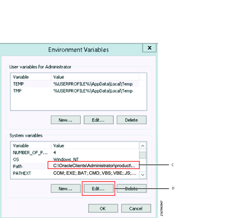
Copy and paste the text in the Variable Value field into any text editor.
Verify that the 32-bit path precedes the 64-bit path in the string. If the 64-bit path comes first, uninstall both clients and follow the instructions in this section again.
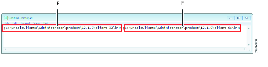
E
;C:\OracleClients\.....\client_32\binF
;C:\OracleClients\.....\client_64\bin
TNSNAMES
To connect to the Oracle database, an alias needs to be added to the tnsnames.ora file.
Tnsnames.ora is located in the Oracle home folder. For example: C:\OracleClients\Administrator\product\12.1.0\client_64\Network\Admin If you don’t have one, you can copy the sample Tnsnames.ora from the sample folder.
Check the following file paths:
C:\<oracle home folder>\Administrator\product\12.1.0\client_64\Network\Admin
C:\<oracle home folder>\Administrator\product\12.1.0\client_32\Network\Admin
for the file
Tnsnames.ora.If the file
Tnsnames.oracan be found in both folders, open each of the files in any plain text editor and make sure that they look like the following.Example of a filled in
Tnsnames.orafile - opened in a plain text editor: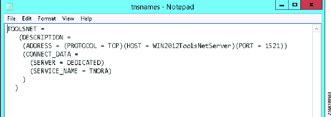
TOOLSNET =(DESCRIPTION =(ADDRESS = (PROTOCOL = TCP)(HOST =<WIN2012ToolsNetServer>)(PORT =1521))(CONNECT_DATA =(SERVER = DEDICATED)(SERVICE_NAME = TNORA)))If
Tnsnames.oracan’t be found in either folder, copy the sampleTnsnames.orafrom the sample folder into the folders specified above and fill in the<blanks>in the file.Sample file:
Tnsnames.ora- opened in a plain text editor.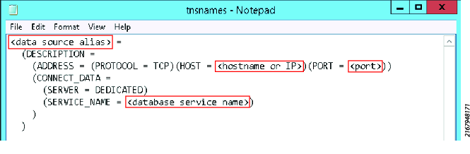
<data source alias>
=(DESCRIPTION =(ADDRESS = (PROTOCOL = TCP)(HOST =<hostname or IP>)(PORT =<port>))(CONNECT_DATA =(SERVER = DEDICATED)(SERVICE_NAME =<database service name>)))
ToolsNet Database Installer
The installer provides a graphic assisted installation of the database modules.
The database module's main functions are:
Saving job: results, identifiers and traces from ToolsNet.
Prerequisites:
ToolsNet 8.8 installation or higher.
Database installer version 4.7.2 installation or higher.
Database Backup
It is recommended that the ToolsNet data collection database is backed up at regular intervals. And also that the backups are stored on a device separated from the production environment in order to secure the data.
Backups are to be performed with SQL Server or Oracle recommended procedures and not through file copying.
For SQL Server it is recommended that backup routines are set up by using SQL Server Management Console. Scripting the backup to a SQL Server Agent Job that can be scheduled and monitored through SQL Server.
Refer to the SQL Server manuals for detailed instructions on how to do this.
Scheduling Database Maintenance Jobs in SQL Server Enterprise and Standard Edition
After installation, maintenance jobs are set up in the SQL Server. These jobs are by default disabled to avoid that production data is accidentally deleted. Delete maintenance is performed by a number of stored procedures with the prefix .tnmt.
It is recommended to use the provided Jobs for the ToolsNet installation:
Job | Purpose | Default values |
|---|---|---|
| All results, graphs and events older than specified number of days to keep will be deleted. The deletion is done in six steps with the possibility to set different values for each step. The default values are the same for all steps 1) Results – non-safety critical 2) Results – safety critical 3) Graphs – non-safety critical 4) Graphs – safety critical 5) Events 6) MaintenanceLog | Days to keep = 100, Bulksize = 5000 (rows/transaction)Schedule is every day at 01:00
Job is disabled |
| A job to delete all unbound graphs, i.e. traces without a result that have been sent to ToolsNet. | Days to keep = 1 BulkSize = 5000 Schedule everyday at 23:00 Job is enabled. |
| Rebuilds the indexes physically on the hard drives. Scheduled to run once a week. Makes all transactions and searches faster. | No settings to change. Job is enabled. Scheduled every Sunday at 03:00 |
| Reorganizes the indexes. Scheduled to run once a day. Makes all transactions and searches faster. | No settings to change.Job is enabled. Scheduled every day, but Sundays, at 03:00 |
Select Start , and then select All Programs.
Select Microsoft SQL Server, and then select SQL Server Management Studio.
On the SQL Server Management Studio dialog box, expand SQL Server Agent, and then expand Jobs.
In the Jobs folder, select a Job to configure the Job settings.
In the Select a page list, select Schedules.
Select the job in the Schedule list, and then select Edit.
In the Job Schedule Properties window, define the schedule as desired.
To make the job run from now on, select the Enabled check box.
Select OK.
Index Reorganize and Index Rebuild in Oracle
Heavily fragmented indexes can decrease application and database performance. The Database Engine can be configured to automatically maintain indexes.
Index reorganize and Index rebuild are set up as a job in the Oracle Agent. The reorganize job should be run once a day on a database. With many transactions the rebuild job should be run once a week.
The index maintenance is set up with this schedule by default.
ToolsNet Archive Installer
There are two types of Archive Installer's available:
Archive Installer (version 9) - ToolsNet 8.18 installation or higher.
Archive Installer (up to version 9) - ToolsNet 8.8 installation or higher.
Archive Installer - ToolsNet 8.18 installation or higher
The installer provides an assisted installation of the archive modules.
Archiving Services - Connects the web to the archive databases and copies results, identifiers and traces from the ToolsNet database to the archive.
Prerequisites:
ToolsNet 8.18 installation or higher.
Archive installer version .net 4.8.
Starting the Archive Installer Application
Open the file explorer and go to C:\ProgramData\Atlas Copco\ToolsNetDatabase\ToolsNetDatabase scripts\Archive database.
Select ArchiveInstaller.exe to open the Archive Installer dialog box.
Archive Installer - ToolsNet 8.8 up to 8.18 installation
The installer provides an assisted installation of the archive modules.
The archive module's two main functions are:
Archiving Job: Copies results, identifiers and traces from the ToolsNet database to the archive.
Archiving Services: Connects the web to the archive databases.
Prerequisites:
ToolsNet from 8.8 up to 8.18 installation.
Archive installer version .net 4.8.
Starting the Archive Installer Application
Open the folder C:\ProgramData\Atlas Copco\ToolsNetDatabase\ToolsNetDatabase scripts\Archive database.
Start the application ArchiveInstaller.exe.
Enabling ToolsNet Archiving
In the SQL Server Agent > Jobs folder, enable ToolsNet_Archiving.
Day limit for export must be set to get the Archive functionality.
Adding Port Range for Archive on a Separate Server
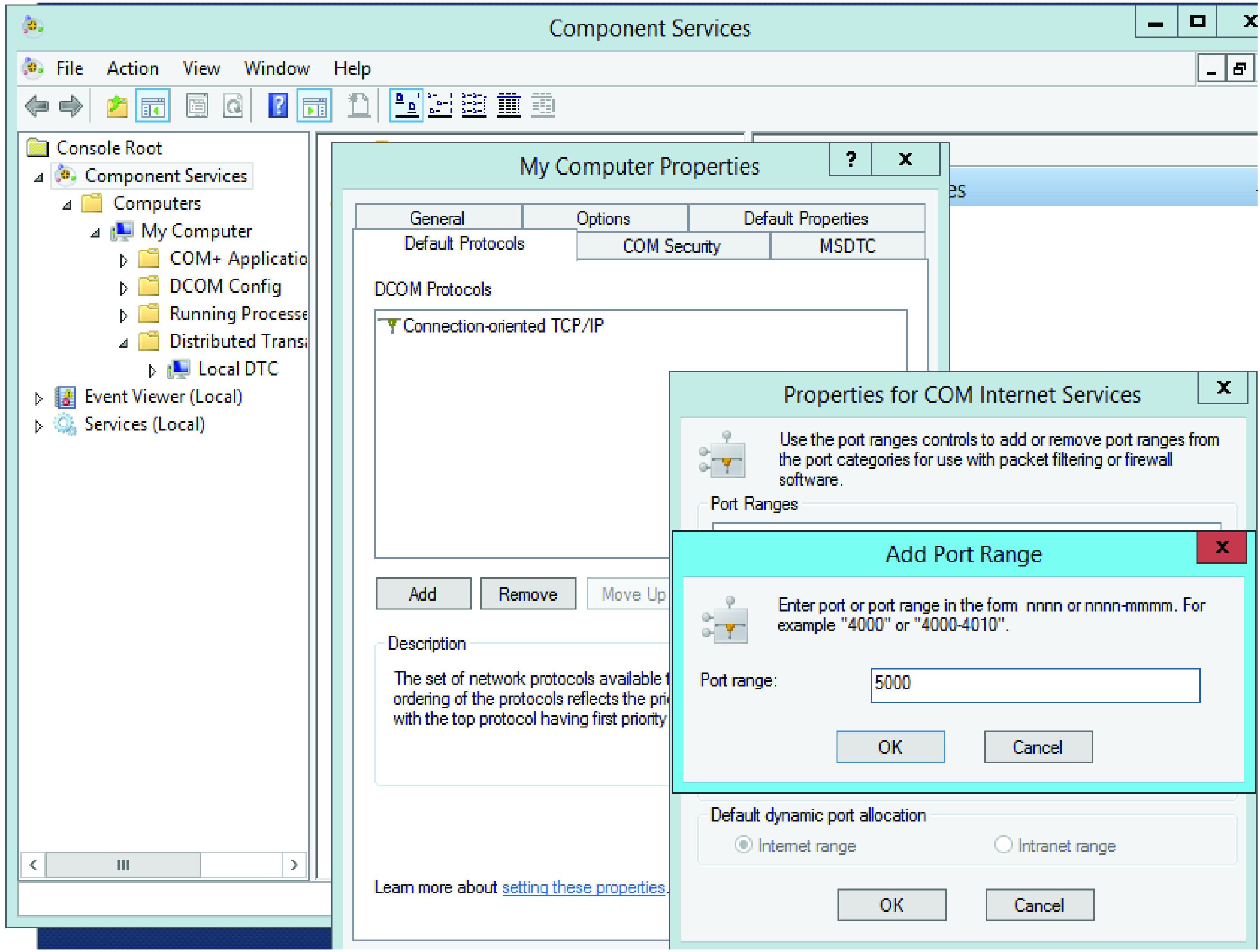
In Component Service > Computers > My Computer > My Computer Properties > Default Protocols > Properties for COM Internet Services > Add Port Range, set the port range according to 5000, and select OK.
In the Properties for COM Internet Services, select OK.
Setting Local DTC Properties for Archive on a Separate Server
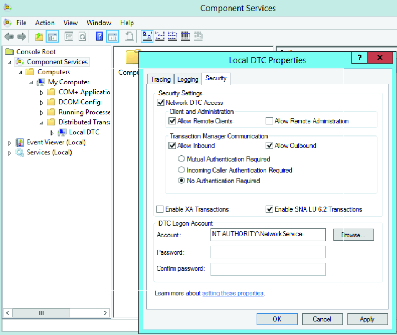
In Component Service > Computers > My Computer > Distributed Transaction Coordinator > Local DTC > Security, mark the check boxes according to the table.
Feature
Settings
Network DTC Access
enable
Allow Remote Clients
enable
Allow Inbound
enable
Allow Outbound
enable
No Authentication Required
enable
Enable SNA LU 6.2 Translations
enable
(DTC) Account
NT AUTHORITY\NetworkService
Select Ok
Setting the Days Limit For Export for Archive on a Separate Server
Use the Days Limit For Export function for determining when archiving starts.
SET @DaysLimitForExport default value 9999 days = (no archive function).
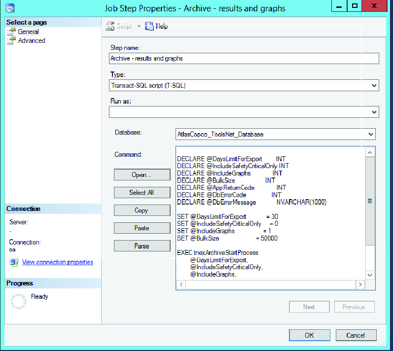
In the SQL Server Agent, Jobs folder, select ToolsNet_Archiving.
In the page Steps, select Archive - results and graphs.
In SET @DaysLimitForExport, set the number of days passed before archiving, and then select OK.
Creating the Archive Database
How to create a database archive on a server.
Installation is applicable to SQL Server or Oracle.
The Archive Installer has guiding text for each field.
In the Archive Installer dialog box, go to the Create Archive tab and enter the fields as stated below.
Database type - Select SQL or ORACLE.
DatabaseInstaller path - The path is by default set to C:\ProgramData\Atlas Copco\ToolsNetDatabase\ToolsNetDatabase scripts\AtlasCopco.DatabaseInstaller.exe. If you want to configure it to another path, enter a new path in the path field, or.select Browse to access the location.
Archive instance - Enter an IP address or archive database server, where the archive target database is to be stored.
User Name - Enter the name of the user to be used for the archive database.
Password - Enter the password used for the archive database installation.
Archive name - Enter the name to be used for the archive database.
Archive Location - Enter or browse the location of where the archive database is to be saved. The location needs to be in the C drive and it needs to be manually added if on a remote server.
Only available in database type SQL.
Log file location - Enter or browse the same location used in Archive Location . The location needs to be manually added if on a remote server.
Select Install to run the installation to create the database for archiving.
If the installation has been successful a dialog box will be displayed. Select OK .
If the installation has been unsuccessful, an installation error dialog box will be displayed. Select OK and go back and check the entered fields.
For the database archive to work, a link needs to be configured between the archive database and the ToolsNet database. See Creating Link to the Database.
Creating Link to the Database
How to create a link to from the archive database to the ToolsNet database and connect them.
Installation is applicable to SQL Server or Oracle.
The Archive Installer has guiding text for each field.
In the Archive Installer dialog box, go to the Create Link tab and enter the fields as stated below.
DatabaseInstaller path - The path is by default set to C:\ProgramData\Atlas Copco\ToolsNetDatabase\ToolsNetDatabase scripts\AtlasCopco.DatabaseInstaller.exe. If you want to configure it to another path, enter a new path in the path field, or.select Browse to access the location.
ToolsNet database instance - Enter an IP address or archive database server of where the archive information is to be stored.
Only available in database type SQL.
ToolsNet database name - Enter the ToolsNet database name. For normal installation use AtlasCopco_ToolsNet_Database
User Name - Enter the name of the user to be used for the archive database.
Password - Enter the password used for the archive database installation.
Only available in database type SQL and applicable to installations up to ToolsNet 8.18 installation.
Linked Server Name - Two options are available for this field.
If the Archive database instance has the same IP address or archive database server as ToolsNet database instance, then the entry field will be disabled and the message No link will be created will be displayed.
If the Archive database instance has a different IP address or archive database server as ToolsNet database instance, then it is possible to enter the linked server name in the field.
Archive database instance - Enter the archive target database source, it should be the IP address or archive database server where it is stored.
Archive database name - Enter the archive database name.
Only available in database type SQL and applicable to installations up to ToolsNet 8.18 installation.
Linked Server provider - The field will have the default entry SQLNCLI11.
Start date - Select the start date, for when the archive will run from.
End date - Select the end date, for when the archive will run to.
Select Create link to configure the link between the source and the target.
If the installation has been successful a dialog box will be displayed. Select OK .
If the installation has been unsuccessful, an installation error dialog box will be displayed. Select OK and go back and check the entered fields.
Upgrading the Archive Database
How to upgrade the database archive on the server.
In the Archive Installer dialog box, go to the Upgrade Archive.
In the Setup Configurator section:
If the Status is Disonnected (red), a connection needs to be established, see Setting Up the Connection Properties.
If the Status is Connected (green), and the ConnectionString is True, enter or select the DatabaseInstaller path to the database.
Select Connect to ToolsNet to view any upgrades available.
If any upgrades are available it will be listed under Database to upgrade. Select an item from the list and select Upgrade, to upgrade the database.
Type of Upgrades
How to view the type of upgrades available.
Major upgrades are always denoted by an integer.
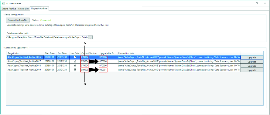
A | Minor versions |
B | Major version |
Possible upgrades
Archive contains no data = the Has Data check box is not selected, a Major version to a Major version upgrade is possible.
Archive contains no data = the Has Data check box is not selected, a Major version to a Minor version upgrade is possible.
Archive contains no data = the Has Data check box is not selected, a Minor version to a Major version upgrade is possible.
Archive contains no data = the Has Data check box is not selected, a Minor version to a Minor version upgrade is possible.
Archive contains data = the Has Data check box is selected, a Major version to a Minor version upgrade is possible.
Archive contains data = the Has Data check box is selected, a Minor version to a Minor version upgrade is possible.
Not possible upgrades
Archive contains data = the Has Data check box is selected, a Minor version to a Major version upgrade is not possible.
Archive contains data = the Has Data check box is selected, a Major version to a Major version upgrade is not possible.
Setting Up the Connection Properties
How to set up the connection to the server.
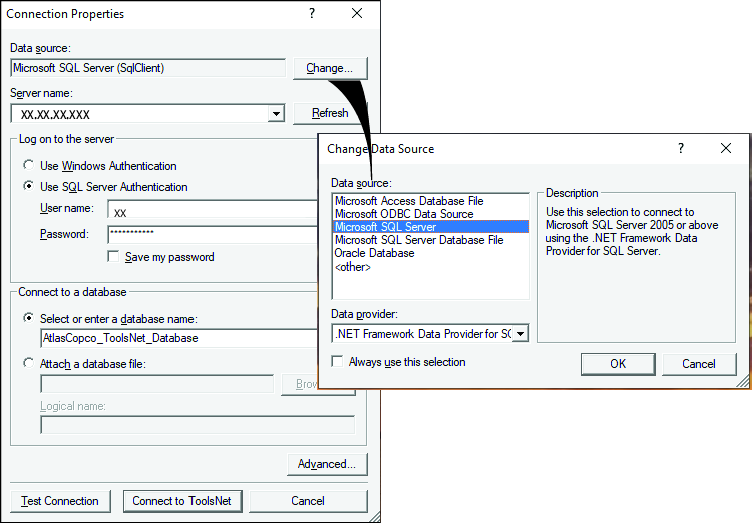
In the Connection Properties dialog box, go to the Data source and select Change.
In the Change Data Source dialog box, select the data source to be used.
Select OK, which will take you back to the Connection Properties dialog box.
Enter the Server name (IP address), or select from the dropdown list.
In Log on to the server select either Windows Authentication or SQL Server Authentication to log on to the server.
For SQL Server Authentication enter the User name and Password. Select Save my password for easy access in future.
In To connect to a database select either Select or enter a database name or Attach a database file.
For Attach a database file browse for the file and enter the Logical name.
Select Advanced to choose further entries from the Advanced Properties dialog box, and select OK to apply.
Select Test Connection to check if the connection works or select Connect to ToolsNet to connect.
Operation
In this section, you can find step-by-step information about how to operate the product.
Getting Started
Accessing ToolsNet 8 is only possible after a complete server installation.
Start your web browser.
In the address field, enter IP address/ToolsNet or server name/ToolsNet
Example of an IP address: http://10.46.19.29/toolsnet
Press Enter.
The User selection menu opens.
Working with the User Account
First time users have to create a new user account to be able to work with ToolsNet 8. The user account contains personal information like Name and Email.
When using ToolsNet 8 for the first time or when you sign out, the User selection dialog box will automatically open.
Creating a New User Account
In the User selection dialog box, select Create new.
In the Create new user dialog box, insert Name and Email address, and then select OK.
Select an Existing User
In the User selection drop-down list box, select Select.
In the drop-down list box that opens, select an existing user, and then select OK.
Modifying the User Settings
The Settings is divided into sections:
User information.
User settings.
Generic Reports.
Tightening.
Adhesive.
Process.
Global favorites (applicable depending on availability).
Analysis global favorites (applicable depending on availability).
On the top menu bar, select the expand button
 , and then select Settings.
Enter the User information needed for functions such as notifications.
Enter the User settings needed for functions such as language and units. Uncheck Always verify before leaving reports if notifications when leaving a report is not needed.
Select the Tightening check boxes to decide which reports should be visible in Tightening.
Select the Adhesive check boxes to decide which reports should be visible in Adhesive.
Select the Process check boxes to decide which reports should be visible in Process.
Select the Global favorites check boxes to decide which global favorites should be visible.
When a favorite is set as Global it is available to all users to add in their settings. If the check box is not selected, the favorite is only visible to the user creating it.
Select the Analysis global favorites check boxes to decide which Analysis global favorites should be visible.
Select Save.
Signing out
Select Sign out to return to Selecting a user.
Working with the Search Panel
The search panel area is available in the centers within the Reports, Statistics and Analysis tabs to generate results.
A | Tabs Multiple tabs can be added and removed for the Reports and Analysis tab. Select the + button on the tab bar to add or remove a tab. See Microvideo. |
B | Search Area The standard search area is displayed on the upper section. The advanced search area will appear in the lower section, when you select the Run advanced report toggle. It offers additional filter criteria for a more detailed search. |
C | Button(s) Select button to generate and view results. Reports > Run report. See Running a Report. Statistics > Calculate. See Running a Statistics Result Analysis > Select. See Running an Analysis To save a search criteria as favorite, select Save as Favorite. Only applicable to Reports. See Managing a Favorite Result |
Search Criteria in Tab
How to work with the different search criteria that appear in the search panel.
The search panel is available for centers within the Reports, Statistics and the Analysis tab. The search will generate data from the ToolsNet database. There is a standard search panel in the upper section. An advance search section can be available in some tabs and centers. It is accessed by selecting the Run advanced report toggle.
The types of search criteria that can be selected will differ between the tabs and centers.
Search Criteria | Description | Working with the Criteria |
|---|---|---|
Tool structure | Tree folder listing specific Tool, Controller Group, Specific Controller or Virtual Station. | Select All or open up folder structure and select a specific product. |
Date range | Preset date ranges or calendar to select from. The Date Range selection box is used to define the dates for a measurement and therefore reduce the number of search results. Choose either a predefined date range, or create a custom date range using the Custom range feature. | Select Apply to add date range. |
Max results | The amount of results to be shown in the result list. | There are 6 options, ranging from 50 to 5000. |
Status | The Status selection is used to narrow down the search to a specific result. The number of selections varies depending on the application. Choose one of the status options that you wish to save. | Select to expand and select a specific status from the list. Different options are listed and shown depending on the center. The default status might also differ.
|
Program | The Program selection box is used to define a specific program for a measurement and therefore reduce the number of search results. Choose one of the available Programs from the list, or enter the Program name directly. | Select ALL or a program from the list. |
Bolt | The Bolt selection is used to narrow down the search to a specific bolt within a mass tightening pattern. In the Bolt item list, select the specific bolt within the tightening, for example, number 3, for the third bolt within the mass tightening. | This field is by default set to All . |
Identifier | The first Identifier selection is a user defined way of keeping track of the different tightenings, for example, bar-codes or VIN in an assembly line. | Enter an identifier or select from the list. |
Identifier (grey) | The second Identifier selection is used for search combinations by using two identifiers. | Enter an identifier or select from the list. |
Shift | It is possible to connect results to a certain shift as they are reported from the controller, by tagging new results with the shift. One shift can be a maximum of 24 hours and in Administration it is only possible to start a shift after today's date. | Shifts can be managed in Administration. It is possible to connect results to a certain shift as they are reported from the controller, by tagging new results with the shift. In Reports, shift has been added as a criteria in Result, Result Summary and Top NOK reports. One shift can be a maximum of 24 hours and in Administration it is only possible to start a shift after today's date. |
Value type | The Value Type is used to filter the search to a specific angle or torque selection. | Select a value type from the list. When using Value Type, always set a Min Value and the Max Value |
Min value | The Min Value selection box is used to narrow down the search to a specific step within a job sequence. | Enter the value in the field or select arrows to go up or down. |
Max value | The Max Value selection box is used to narrow down the search to a specific step within a job sequence. | Enter the value in the field or select arrows to go up or down. |
Job | The Job selection is used to narrow down the search to a specific Job. | Enter a job name or select a job from the list. |
Steps | The Steps selection box is used to narrow down the search to a specific multistep tightening. | This field is by default set to All . |
First record | The First record selection box is used to define the dates for a measurement and therefore reduce the number of search results. Choose either a predefined date range, or create a custom date range using the Custom range feature. | Select to expand preset date and select Apply or create Custom range dates and times and select Apply. |
Location | Tree folder listing specific stations available. | Select to expand to filter the search to a specific location within the Location structure. |
PIN1 | The product identification number. | Enter a product identification number. |
VIN1 | The vehicle identification number. | Enter a vehicle identification number. |
Sequence1 | The order a tool is used. | Enter a sequence number of the product. |
Model | Models put together. | Select to expand and either enter specific model in box, select a specific model available from the list or select All. |
Result records | The history of the assembly process. | Select to expand and select the result record from list: All - displays all results of the complete history of the assembly process. First - only displays the initial status of the assembly process e.g. initial status of tightening attempts. Once set, the report will only show the initial existing result of an assembly process (tightening, manual confirmation, and barcode). The NYD status will be shown for the respective process to best understand the expected process. Last - displays the final status of the individual assembly process e.g. the final status of all tightening attempts, and not all steps in between. Once set, the report will only show the final existing result of an assembly process (tightening, manual confirmation, and barcode). If no result has been received yet, then the NYD status will be displayed for the respective assembly process. First Attempt - displays the first attempt of an assembly process, the first result that is not an NYD. First Time Right - displays all assembly process that were not OK on the first attempt. |
Event level | The Event Level selection box is used to narrow down the search to a specific type of event. The selectable events are: All, Info, Warning or Error. To specify the Event Level search, use Event Code in combination with a specific level. | Select one option: All, Info , Warning or Error. |
Event code | The Event Code selection box is used in combination with a specific event level to narrow down the search. | Select numerical number manually or by using the arrows. |
Joint group | The mass tightening fixtures | Enter a joint group. Handling results will be shown in the second level (Number, Description). |
Joint | The tightening of the bolt. | Enter a specific joint. Handling results will be shown in the second level (Number, Description). |
Part Name1 | The product part name. | Enter a part name. |
Barcode1 | The product barcode. | Enter a barcode. |
PR Family1 | The product family. | Enter a product family. |
PR Name1 | The product name. | Enter a product name. |
Program name | The Program Name selection box is used to define a specific program for a measurement and therefore reduce the number of search results. | Enter a program name or select a program from the list. |
Group size | All results can be grouped according to a selectable size, called Group size. The Group Size selection is used to specify the number of results (statistics samples) used for a calculation. Statistics population example using Group Size 7: The first dot in the graph series will be the average of the first 7 results and the next dot is the average of the next 7 results. | Select one of values from the list. |
Max results | The Max results selection box is used to narrow down the search to a max results per criteria. | Select one of values from the list. There are 6 options, ranging from 50 to 5000. |
Max results per criteria | The Max results per criteria selection box is used to narrow down the search to a max results per criteria. | Select one of values from the list. |
1The free text search boxes allows for the usage of the wildcard character asterisk (*) at the start, middle or end. For example, entering "Name*", returns all entries that start with "Name". Entering "*Name", returns all entries that end with "Name". Up to 25 characters can be used within the search box field.
Managing a Favorite Result
In Reports, it is possible to add favorite buttons for easy access to your favorite selections. In favorites, the selection settings and the grid state are saved. The favorite box contains information about the type of report and if the favorite is global or not.
Saving a Favorite Result
In the Choose report settings panel, select one of the report categories.
Select the Run report expand button, and select Save as favorite.
In the Name text box, name the favorite button (15 character maximal text input).
Select the Color selection box and select a button color (optional).
In the Description text box, describe the favorite button function. The description is displayed in a pop-up when hovering over with the cursor.
Mark the Global check box, in order to make the favorite button global, or leave the check box unmarked to make the favorite button personal.
Select Save.
Once saved, a new box will be created and added to the Reports tab.
Deleting a Favorite Result
Go to the Reports tab.
Select X on the favorite box.
Select OK in the message box.
Working with the Results
When a result has been generated, from your search, it will display details of information in table format with list, column and graphs, if applicable.
Result List
A | Result title Displays the title of the search result generated. |
B | Icon action Select icons to:
|
C | Data of results Displays data of the search result. Not applicable to all result centers. Not applicable to all results generated. |
D | Drag a column header and drop it here to group by that column Select a column and drag-and-drop it into the actual text, to view further detailed information of the specific column. More than one column can be added, see Creating a Group within a Group. The column name selected will be added to this section. The result table view will change. To manage the content displayed:
|
E | Column row Displays the title of the information within the column. Select the title name to sort the order of the content of the column. An up or down arrow will appear. |
F | Column and options Select expand button to view box alternatives:
See Customizing Columns. |
G | Trace Select the box in the title area to view 50 first traces or select one or more boxes within each row. Select the trace icon to open up a new tab displaying further trace information. See Working with Trace. |
H | Row Each row contains data. Select expand button |
I | Table Row Report Tabs Select expand button of row Trace - View trace result. Details - View overview details of the result. Events - List of events for affected units. See column for feature description. Program - View overview of the program corresponding to the result. If available, select the expand button below the table to view further results or select expand button to collapse the view. For the further results shown, select the plus icon (+) to collapse or expand information shown. Steps - Displays the steps available. Select the row expand button to display further information, or select to collapse and hide the information. Comments - Enter to add comment or exclude in the statistics. Unit change log - List of log for affected units. To work with the columns, see Customizing Columns. See Working with the Trace Results and Working with the Table Row Tab Results for further information. |
Customizing Result List
It is possible to customize the column width, column order and to show or hide the columns in the result list. The customization can be saved to your ToolsNet 8 user. The saved customization is saved to the user profile and is always used for this specific report type, until it is reset.
Select Save to save the customization settings.
Select Reset to return to the default result list settings
Settings not saved:
sorting orders
filter settings
groups
groups in groups
Customizing Columns
When working with ToolsNet 8 it is possible to customize further the content within the columns.
Drag and Drop Column
Columns can be moved to a position of your preference.
Select column header and drag it to desired position and drop it.
Order Column
Select the expanded button of one of the result list headers.
In the drop-down list, select Sort Ascending or Sort Descending.
A black arrow pointing up or down appears on the result list header.
Adding or Removing Columns
Used for adding or reducing data columns in the result list. Useful for reducing empty results.
Select one of the result list headers.
In the drop-down list, go to Columns to view a list of all available column headers.
Mark or unmark the relevant check boxes, to Add or Remove the columns in the results.
Using Filters
Use filters to reduce the result quantity and to get a more accurate result.
Filter settings:
Is equal to
Is not equal to
Starts with
Contains
Does not contain
Ends with
Combination of filters:
And
Or
For example:
[Is equal to] [Or][Starts with] --> (value)
Working with the Trace Results
For the results generated in the Reports tab, it is possible to access and view trace results within the list result in different ways.
Trace - Row
Select the row expand button
 for one of the listed results.
The trace will be displayed in the Trace tab.
Select a trace to view further detailed information of the trace. A separate tab will open up, see Trace view.
Trace Checkbox - Column
Select the checkbox
 of one or more results.
Select the trace icon
 to view further detailed information of the trace. A separate tab will open up, see Trace view.
Multiple Trace - Column
Select the column checkbox Trace
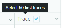
Select the trace icon
for one of the results, to view further detailed information of the traces. A separate tab will open up, see Trace view.
Trace View Tab
The Trace view tab opens up when selected from the result list, generated from the Reports tab centers.
The trace view displays detailed joint analysis, using data from measured torque and angle values for a specific rundown. The information is either shown as a data table, or a combined chart and data table.
Trace results are only available if trace results are sent out from the controller.
The following traces can be selected and viewed:
Torque/Angle
Torque/Time
Angle/Time
Speed/Time
Current/Time
Traces for MicroTorque and PF6000 display optional trace data in Torque/Angle, depending on the controller settings.
Seating point in trace:
Rundown complete
First torque
Final torque
When working and analyzing the trace it is possible to do the following:
Hover on the trace to view further detailed data.
Draw a box in a specific area to zoom in.
Select and hold the shift key and drag, to pan or zoom an area. See Microvideo.
Select Reset zoom to go back to the original view.
Select the more icon to Print or Export the trace details.
Select or deselect a trace from the list displayed to view or hide the trace.
Use Sync traces - synchronize and compare the traces in an easy way. It is possible to select different sync values for example, Peak, Rundown Complete or First Target.
Select one of the trace curves to open the Magnified view of graphs.
View further details in the table below the trace:
General
Torque
Angle
Microvideo
Exporting or Printing the Trace View
It is possible to export or print a trace view regardless of the menu.
In the result list, select the Magnified view of graphs button
to open the Trace view.Print the graph by selecting the Chart context menu button
 in the upper right corner of the graph, and select Print.
Export the data to Excel™ by selecting the Chart context menu button
in the upper right corner of the graph, and select Export.
Microvideo
Trace Limit Offset
The Start final angle point is set in the program as a torque value. The torque value has an undefined angle, called Offset value. From the Start final angle point it is easy to determine an angle to Final torque. The tightening must hit Final torque between Low limit angle and High limit angle. The value in brackets is 'Start final angle' + the limit value.
Example, Low 70 (334,7), where 70 is the Low Limit (C), and (334,7) is the offset value + Low Limit value (B+C) .
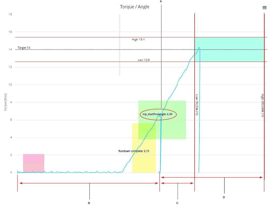
A | Start final angle (torque value) |
B | Offset |
C | Low Limit (Low Limit+offset) |
D | HighLimit (HighLimit+offset) |
Synchronizing Traces
Synchronize will give the user a clearer view when comparing traces.
Synchronization example.
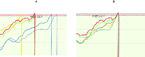
A | Not Synchronized | B | Peak Synchronized |
In the list of results, mark the check box
of more than one of the results.Select the trace button
for one of the results.In the Sync traces multiple trace view, select one of the following synchronizing methods:
Not synced- (default).
Peak - for synchronizing in highest measured torque.
Rundown complete - for synchronizing in rundown complete.
First target - for synchronizing in first target.
Start final angle - for synchronizing in start final angle.
Microvideo
Working with the Table Row Tab Results
When results are generated within the Reports Tab, further tabs can be displayed when expanding a row in the result table.
Trace Tab
See Working with the Trace Results for further information.
Details Tab
The Overview window can be expanded by clicking the unfold button  .
.
In the expanded view:
Other is a table presenting all incoming data not shown in Overview.
Error displays specific errors.
Tool displays specific tool information for the result.
Events Tab
The Event tab displays occurred events in the controller +/- 1 minute from the result time. Use Events to recognize if something happened in the controller during troubleshooting of NOKs.
In the result list, select the expand button
for one of the listed results.In the expanded result list, select the Event tab.
Program Tab
Shows an overview of the selected program.
Example:
Program name
Model
Program date
Program number
In the result list, select the expand button
for one of the listed results.In the expanded result list, select the Program tab to open the Overview. The data is divided into General, Monitors and Restrictions on program as well as step levels.
Steps Tab
Displays detailed information about each step in a multistep tightening.
In the result list, select the expand button
of one of the listed results.In the expanded result list, select the Steps tab.
In the Step column, select the expand button to view the settings and functions for each step.
Comments Tab
It is possible to add a comment to a specific result in the Comments tab. For example, use Comments to explain NOKs when the problem has been solved.
Select the Add button.
In the Add Comment window, make a comment in the Note text box and then select Save.
When a result has a comment it will be shown with the comments exist symbol  at the end of the row.
Exclude in statistics
Use Exclude in statistics to excluded a result from the statistics or to explain why result are excluded from the statistics.
Select the Exclude in statistics button.
In the Exclude in statistics window, make a comment in the Note text box explaining the reason for the exclusion and then select Save.
When a result has a Exclude a Result comment it will be shown with the Exclude a Result comment exist symbol  at the end of the row.
Unit Change Log Tab
The Unit change log will show changes made to a unit, for example when a unit has changed name or IP-address.
In the result list, select the expand button
for one of the listed results.In the expanded result list, select the Unit change log tab.
Creating a Group within a Group
It is possible to create a group within another group by dragging a second column header to the group drop area.
In the example, the group Unit name group (B) is dropped within the group drop area behind the Identifier group (A).
It is possible to alter the group order, by dragging the Identifier group (A) behind the Unit name group (B).
In the result lists, the status OK for the specific unit name is shown first and the status NOK for the specific unit name is shown second.
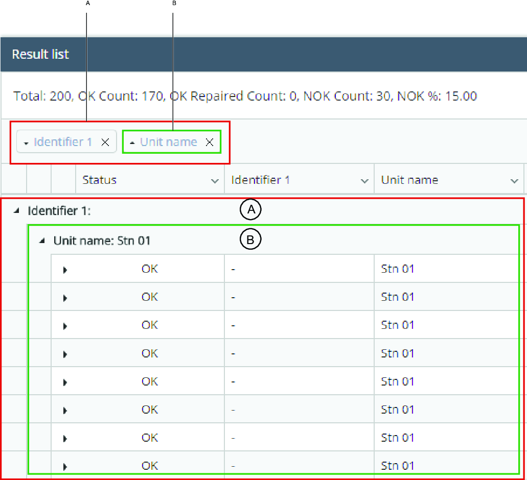
A | Grouped by Identifier | B | Grouped by Unit name inside the Identifier |
Select and hold on one of the column headers.
Drag the column header onto the group drop area.
Exporting Data
Any report can be exported to Microsoft Excel™. The export procedure differ depending on the browser used.
Search for a report.
When the report is displayed, you will see an export icon
 in the top right corner of the report area.
Select the icon to export the underlying report data to Excel™.
Open the report:
Google Chrome™ - In the window footer, select the ResultReportExport.xlsx icon to open the report.
Internet Explorer™ - In the dialog box, select Open, Save or Cancel.
Firefox™ - In the Excel™ selection box, select Open with Microsoft Excel™ and then select OK.
Working with the Dashboard Tab
The Dashboard Tab is a licensed feature in ToolsNet displaying widgets. Widgets are configurable and are the supervision of the daily processes. The operator can add or remove widgets, and set up the displayed content of each widget.
Widgets can contain list, column or graphs.
A | Widget name |
B | Widget center A. Toggle Live or OFF. Allows for live feed to be on or off. B. Settings - opens up settings of the widget. C. Save - saves the widget settings. D. Reset - resets the settings of the widget. E. Full screen - expands the view to full screen. F. Collapse - collapses the widget with only top bar visible. G. Close - removes the widget from the dashboard. |
C | Widget area The widget area can contain either list and column, trace, graphs or columns. |
D | Column Drop and drag the column to any position. |
E | Column options Select to view change: Columns allows you to add or remove columns shown for the widget. Filter allows you to filter the content within the column. |
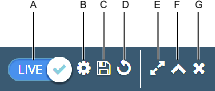
The Widgets Available
Widget | Description | Type | Features |
|---|---|---|---|
Latest results | Shows an overview of the latest results from the chosen part of the of the tool structure The Latest results widget displays an overview of the latest results from the chosen part of the Tool structure.
| Table | |
Reporting units | Shows the units and when they last reported from the chosen part of the tool structure. The Reporting units widget displays units sorted by the latest sent result, or event, for a configured part of the Tool Structure. By default, the complete Tool Structure is displayed. Each PowerFocus 6000 virtual station will be displayed in a separate row, to clearly display when they last reported. Note that a controller can report events not related to a specific virtual station, in these cases the controller will be displayed by itself. | Table | |
Tool maintenance | Shows the tools that needs service or calibration from all the Power Focus tools in production. The Tool maintenance widget displays service and calibration information about the tools registered in the system. In the settings menu, it is possible to select Service or Calibration. The information displayed is based on the following:
| Table | |
Latest traces | Shows an overview of the latest traces for a configured part of the tool structure. The Latest Traces widget displays the 10 latest traces for a specific controller, or virtual station. | Graph | Select any part of the graph to open up a new windows tab with further details on trace. Select trace to open up in a new window for more details |
Running SPC | Shows the real-time X-bar and range charts for a configured application. | Graph | Select a range or bar line to view in table view. The view will change and the LIVE feed will turn to OFF. Select text below the graph to view only the grouped range or bar within the graph. Select one of the two variant parameters below the graph to hide or show each of the grouped parameters. See Microvideo. |
NOK stats | Shows the applications with the highest failure rate for a configured part of the tool structure. The NOK displays the applications with the highest failure rate for a configured part of the Tool structure. | Columns | To view further data of each column, select the column. The view will change and the LIVE feed will turn to OFF. By selecting a specific program you can drill down to see the details of the NOK results. The drill down will show how many of the results in % that have specific errors. |
Microvideo
Managing the Widgets
The Dashboard Tab is preset to display four widgets, when you first start up ToolsNet 8:
Latest results
NOK Stats
Running SPC
Tool Maintenance
It is possible to change the current widgets on display and add or delete widgets. A widget can be moved to a position of your preference, if you select the widget and drop and drag it.
Setting the Widget
Go to the widget you want to amend.
Select the Settings icon
 for the widget.
Choose the settings criteria available for the widget, you wish to change.
Select Save
Widget Settings Criteria
Criteria | Widget | Description |
|---|---|---|
Tool structure |
| Shows tree folder with specific Tool, Controller Group, Specific Controller or Virtual Station. |
Maintenance Type | Tool Maintenance | Select Service or Calibration. |
Status | Latest Traces | The Status selection is used to narrow down the search to a specific result. The number of selections varies depending on the application. Choose one of the status options that you wish to save. |
Program | Latest Traces | The Program selection box is used to define a specific program for a measurement and therefore reduce the number of search results. Select one of the available Programs from the list, or enter the Program name directly. |
Graph | Latest Traces | The Graph selection is used to a specific with graph to view. |
Group size | Running SPC | All results can be grouped according to a selectable size, called group size. The Group Size selection is used to specify the number of results (statistics samples) used for a calculation. Statistics population example using Group Size 7: The first dot in the graph series will be the average of the first 7 results and the next dot is the average of the next 7 results. |
Days | NOK Stats | Amount of days applicable. Enter days or select by pressing the arrow. |
Shift | NOK Stats | It is possible to connect results to a certain shift as they are reported from the controller, by tagging new results with the shift. |
Add New Widget
It is possible to add different widgets to the dashboard using the Add widget button.
Within the Dashboard tab, select the Add widget button.
In the Add widget dialog box, select a widget from the list.
The new widget is automatically added to the dashboard.
Delete Widget
Select the X, in the top right corner of the widget to remove.
Working with the Reports Tab
The Reports Tab is a licensed feature in ToolsNet 8 and provides different views of the collected data in the form of reports. There are a set of standard reports and the reports available are configurable on a user level. It is also possible to preset filters on reports and Save as favorite for quicker data access.
Running a Report
How the results are gathered and presented, are dependent on the filter criteria selected.
Select Reports in the left-side menu, and then select the report center you want to work with.
Select the filter criteria required, see Search Criteria in Tab for further information.
If available, select the toggle for Run advanced report.
The option Run advanced report offers additional filter criteria for a more detailed search.
Select Run report to view the results, or select expand button to Save as favorite, to save the search filter criteria.
Generic Reports
Event
Used for:
To monitor sudden changes and derive the reason for NOK.
Shows the list of the events reported to ToolsNet 8. Each event has a Time stamp, Event level, Event code and Event type according to the controllers’ specification.
Event Summary
Used for:
To monitor frequent events in the plant and use the results for troubleshooting.
Provides the possibility to view the most frequent events in the plant. The search criteria provides the possibility to search for events within a single or in a group of controllers.
Program Change
Used for:
To compare programs and derive changes in the quality differences in results.
Program change lists the latest program version for each program. It is possible to compare two programs of the same type. Drill down shows every version for the program and gives the possibility to compare two versions of on program. When two programs are compared it is possible to show all data or only the changed parameters in the program.
For PowerMACS programs the Program Manager for ToolsNet 8 has to be installed to see the program information.
Program Detail
Used for:
To see all parameters for one specific program.
Search parameters.
Tool Structure
Program
Tightening
Result
Used for:
Getting a report for the tightening results.
Result Summary
Used for:
Getting an accurate summary of the process.
The results generated in the results tab are presented in a list format. The table grid is adjustable and it is possible to save these settings. The result list can also be exported.
Result summary for the combination of Unit, Bolt/Press object and Program version. Shows counts and percentage of OK, NOKs, Calculated Pp and Ppk values for the selected time period.
Top NOK
Used for:
NOK result troubleshooting.
In the List view, the program versions with the highest NOK percentages are displayed first. When the report is expanded, the most frequent errors for the program version are displayed.
In the result list, select the expand button of one of the listed results to display the errors.
In the Tree view, the Top NOK reports are displayed in a tree structure. The structure can be expanded to view the individual results in more detail.
An error notification icon  is displayed in the Error info column when an error report is available.
A single Top NOK result can be the product of multiple errors.
Product
Used for:
To monitor and compare tightening/pressing counts (NOK, OK, and Total) based on a Identifier, for example, a VIN or frame number.
The Product report shows a summary of the result connected to an identifier. It is possible to see the first result time stamp for the identifier and the last result time stamp. It will also summarize the number of NOK and OK for the identifier. The search will show all the results for the selected identifier.
If multiple identifiers are used the results will exist in multiple rows, if the search criteria complies to more than one of the identifiers.
It is possible to search for selected parts of the production line. To search for a shift, create shifts in the Administration Tab.
NOK trend per day
Used for:
Analysis NOK trends and compare with, for example program changes, tool changes or usage of new fastener to see the trend of the made changes.
Shows the number of not ok result for each top folder in the Tool Structure per day. It is possible to view the NOK results both in graphs and in tables.
This report is limited to 31 days of data.
Job Result
Used for:
Analysis of the jobs, for example, to see if the job has a high NOK count.
Shows the job results and batch sequence results for the criteria. It will summarize the number of OK and NOK results within each job.
Job Result Summary
Used for:
To give the possibility to get an easy overview of all jobs and there results.
Gives the possibility to view the performance of a certain job, or batch sequence version.
Top NOK Job
Used for:
To give the possibility to get an easy overview on where changes is needed to improve the quality in the process.
Top NOK Job shows the jobs and batch sequences with the highest NOK percentage first.
Result Step
Used for:
To compare a certain step in a multistep assembly, with the same step in other assemblies.
Result step shows results of the different steps in a multistep assembly.
Adhesive
Result
Used for:
Getting a report for the results of the adhesive joints.
Process
Product
Used for:
Finding information about a specific range of products or a particular product, one may be interested in.
Various search options can be applied optionally in order to narrow down the query, out of which some can be found when clicking on the button Advanced report in the upper right corner. Otherwise, these options are hidden as per default.
Upon clicking on a specific product, it is then possible to see the details of the product: Tightening, Barcodes, Generic results and PR information.
Station
Used for:
Listing all production processes within a specific area, or of even only one single station of the entire production. This supports the user to draw potential conclusions from production deficiencies and the related areas they take place in.
Top NOK
Used for:
Getting statistics about amount and rate of NOKs processes in the production. This allows the user to identify those processes which come with very high NOK rates, thus to focus improving the ones which will have the biggest impact on cost savings and quality, when improved.
Production Overview
Used for:
Identifying potential process issues in the production area by receiving an aggregated process NOK percentage for the individual production sections.
Archiving
Archive Result
Used for:
To show result reports based on archived material.
Archive Product
Used for:
To show product reports based on archived material.
Working with the Statistics Tab
The Statistics Tab is built to make it easy to get advanced statistics for production applications. In this part of the application it is simple to look at range/x-bar charts, histogram, scatter charts, program compare and statistical analysis of traces.
The ToolsNet statistics package gives an efficient statistical evaluation of the assembly process. It includes process control charts, capability and performance evaluation as well as ordinary descriptive statistics. The methods used are based on the ISO 7870 and ISO 22514 series, valid November 2016.
Running a Statistics Result
How the results are gathered and presented, are dependent on the filter criteria selected.
Select Statistics
Select the filter criteria required, see Search Criteria in Tab for further information.
Select Calculate to view the results.
Statistics Tab
In the Statistics tab, the statistic results are displayed in text without a diagram. Selection of two programs is possible, statistics from both programs are then displayed.
The results can be exported and then opened in an Excel sheet.
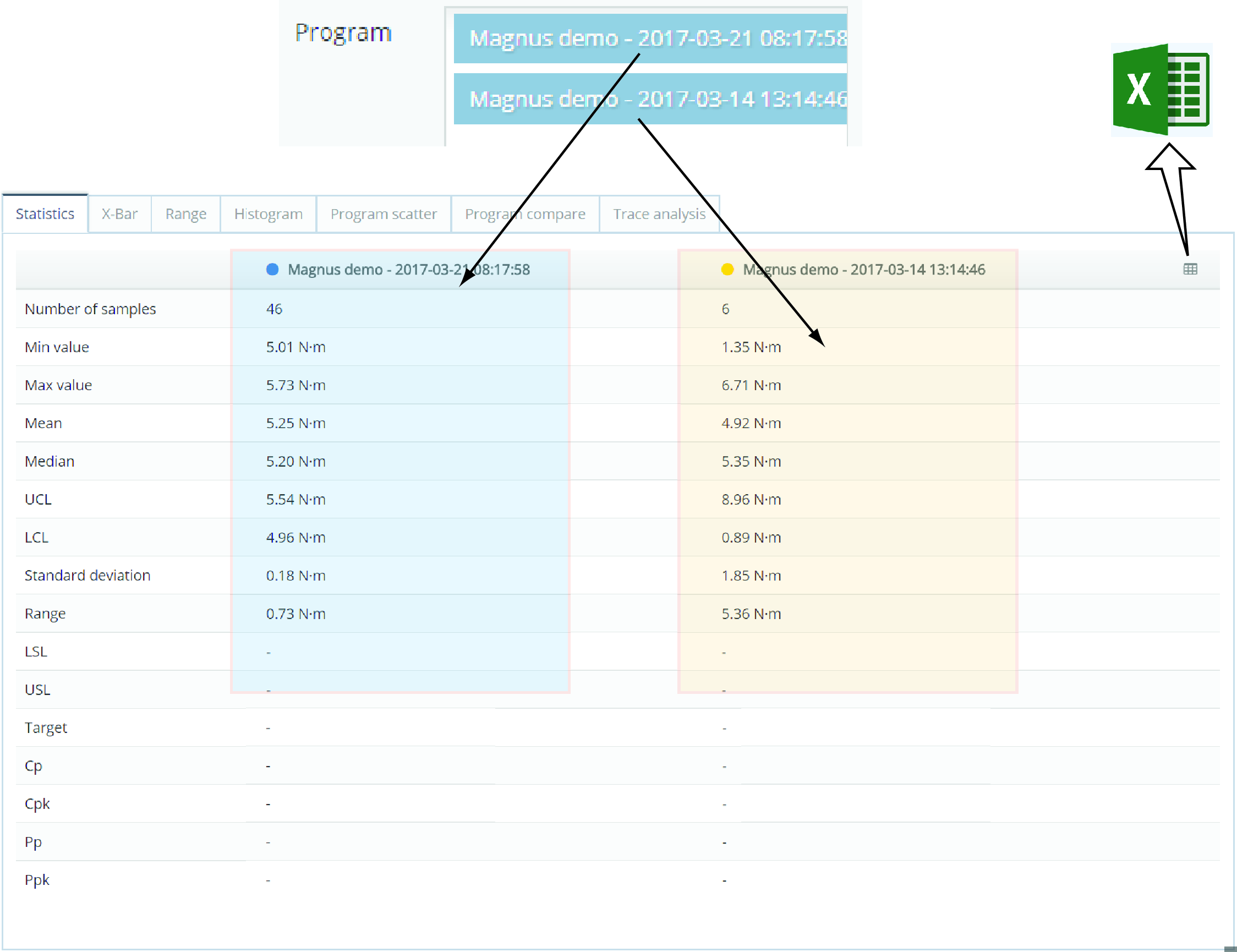
X-Bar Tab
The X-Bar tab displays x-bar graphs of the selected programs. The chart plots the process (mean over time) for the groups. In the X-Bar tab the results are grouped by the Group size (2-15) value and presented as plots.
Plots will be marked red if they:
are outside the upper control limit (UCL) or lower control limit (LCL).
show 7 or more consecutive increasing or decreasing plots.
show 7 or more consecutive plots above or below average.
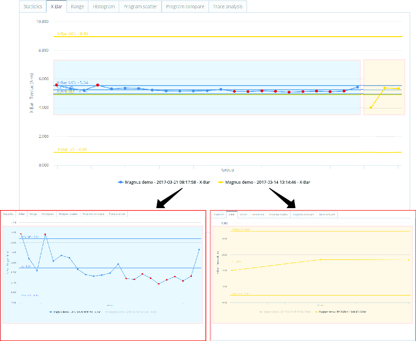
Range Tab
The Range tab graph displays the range chart of the selected program. A range chart plots the process range (difference between highest and lowest value) over time for the selected groups.
Plots will be marked red if they:
are outside the upper control limit (UCL) or lower control limit (LCL).
show 7 or more consecutive increasing or decreasing plots.
show 7 or more consecutive plots above or below average.
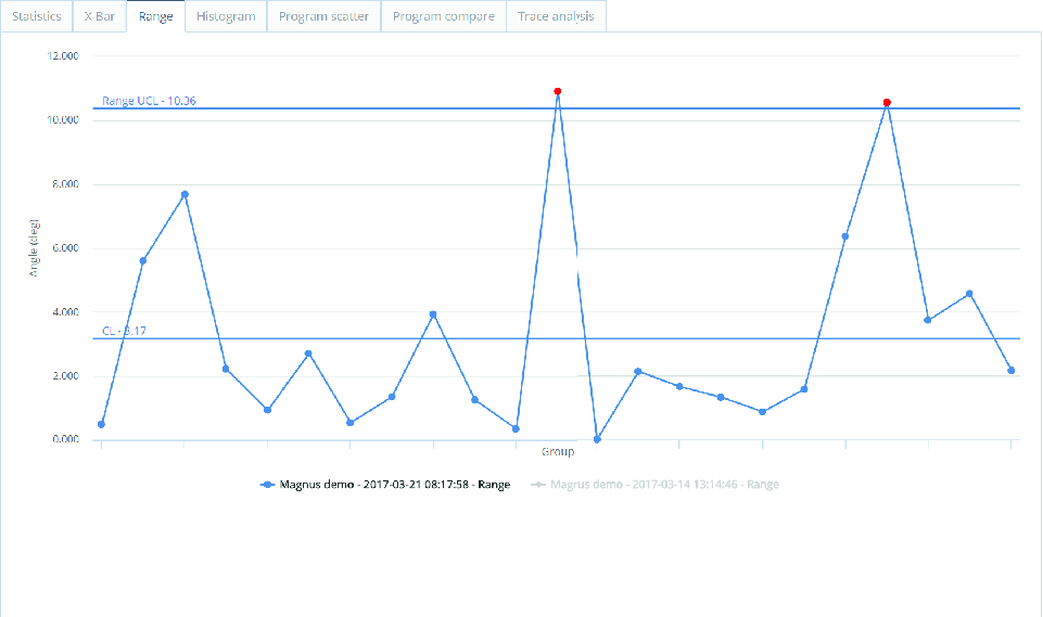
Histogram Tab
The Histogram tab displays the probability distribution of the data set. The graph will also display a Gauss curve with the normal distribution for the corresponding data.
If two programs are selected, both will be shown for comparison.
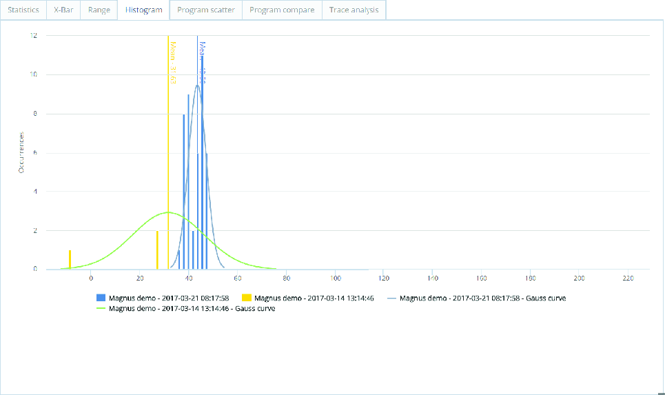
Program Scatter Tab
The Program scatter tab displays a scatter diagram with the accuracy of the results in violation to the limits. It is also possible to identify and follow up outlines. It is possible to adjust the limit lines to change OKs into NOKs, or NOKs into OKs. The adjustments made are displayed in two tables. These are useful when fine-tuning the limits.
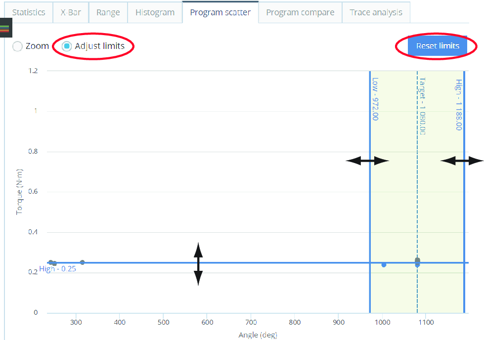
General | Changed status |
|---|---|
Total | OK to NOK count |
OK Count | OK to NOK % |
NOK Count | NOK to OK count |
NOK % | NOK to OK % |
Select to select the Adjust limits radio button.
Select and hold to drag the limit lines one at the time.
Select the Reset limits button to reset to the initial limits.

Select Zoom.
Select and hold the left mouse button to drag a rectangle around the area to zoom in on (repeat to zoom more).
To pan the zoom area in any direction, select and hold the Shift key and drag.
Select Reset zoom to return to the standard view.
Program Compare Tab
The Program compare tab is for comparing two programs. The default view only shows the parameters that differ between the programs. Use expand to show all parameters for the program.
The selection Show only changed parameters  , is used to filter out the changed parameters in the program comparison.
In the Program item list, select one of the available programs, or enter the program name.
In the Program item list, select another of the available programs, or enter the program name.
You can make a maximum of two (2) selections in the Program selection box, both need to be from the same system type.
Trace Analysis Tab
The Trace analysis tab displays statistics based on the selected traces. It is possible to compare two programs, as long as they are of the same system type.
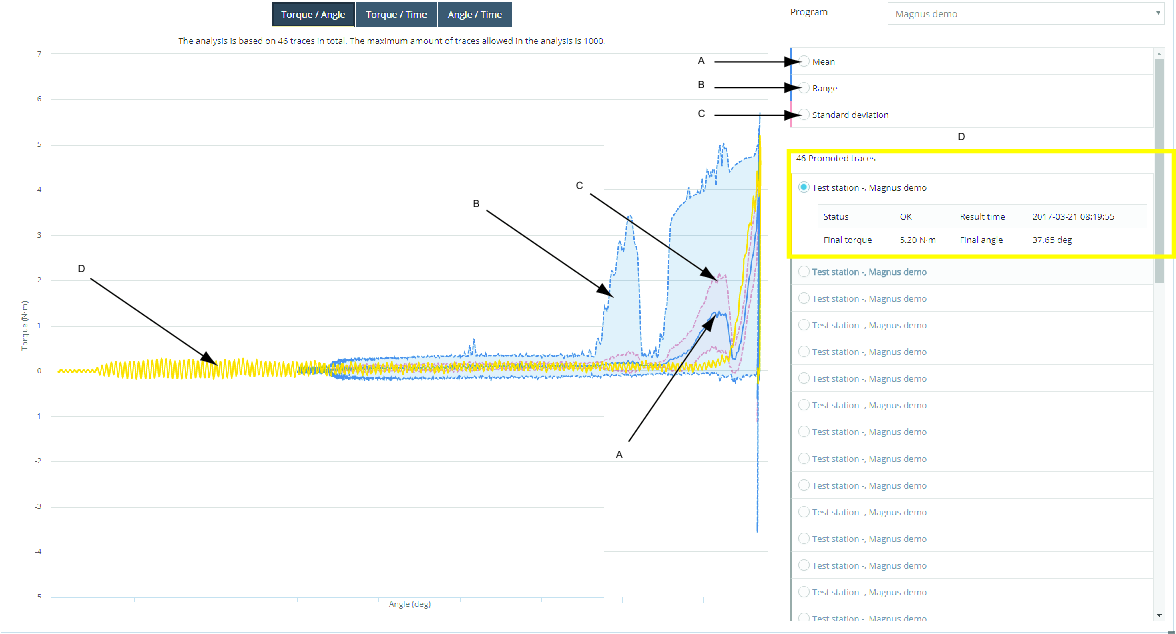
A | Mean | C | Standard deviation |
B | Range | D | Result trace |
The maximum amount of traces allowed in the analysis is 1000.
Select trace axis value
It is possible to change values on the trace axis X and Y.
Torque/Angle
Torque/Time
Angle/Time
In the Program drop down list, select the program to analyze.
Select one or more of the statistics curve names to display, or hide the curve.
Mean (A).
Range (B).
Standard deviation (C).
Select one or more of the result trace (D) names to display the trace.
Select one of the result trace options to display information about the trace.
Working with the Analysis Tab
The Analysis is a licensed feature used for analysis and identification of deviating traces.
If no reference trace is available, create a new reference trace.
Running an Analysis
How the results are gathered and presented, are dependent on the filter criteria selected.
Select Analysis in the left-side menu, and then select the report center you want to work with.
Select the filter criteria required, see Search Criteria in Tab for further information.
For Trend, select the toggle for Search criteria B to n if applicable.
The option Max results per criteria offers the choice of the number of results on display.
Select Select to view the results.
For Trends select Calculateto view the results, or select expand button to Save as favorite, to save the search filter criteria.
Box Analysis
There are two result sections displayed after running the analysis.
Box analysis
Overview and Results
Analyze Trace Data
Place the cursor on the trace to view data of the torque and angle of the trace.
Zoom and Draw Box
Select the Zoom or Draw box option button.
Zoom - Draw a box in the trace area to zoom into a specific selection.
Draw box - Draw a box in the trace area to create a Box displaying the torque and angle data of the area selected. The user determines the identification boxes positions on the reference trace. The boxes are used for identification of deviating traces. If a trace passes through a box, it is considered a deviation. Place a box in the trace to see the intruding traces being converted from OK into NOK.
It is possible to draw up to ten different boxes in the analysis field. The boxes are colored to match the box results. Move between each box by selecting the Box option button. Select the red cross (x) next to the box to remove it.
Sync Traces
Synchronize the traces using by selecting one of the options for Sync traces:
Select Peak or Rundown complete from the list.
To work and analyze the data shown in the and Results list result:
Overview
The overview section will show a summary of the results generated.
Results
List of results are shown, see the section Working with the Results for further information.
Open row to view further information and specific data.
Place the cursor on the trace to view data of the torque and angle of the trace.
Draw a box in the trace area to zoom into a specific selection. Select Reset zoom to go back to original view.
Product Essentials Tutorial
https://www.youtube.com/watch?v=qj79yfWso5o
Post View Torque Analysis
The post view torque analysis is used to display the consequences of changing post view torque limits based on historical data. The positions of the boxes is given by the controller.
There are two result sections displayed after running the analysis.
Post view torque - The results display the trace view of the results generated.
Overview and Results - Displays further data and information of the results generated.
Analyze Trace Data
Place the cursor on the trace to view data of the torque and angle of the trace.
Zoom and Draw Box
Select the Zoom or Draw box option button.
Zoom - Draw a box in the trace area to zoom into a specific selection.
Box - Draw a box in the trace area to create a box displaying the minimum and maximum values of the area selected. The user determines the identification boxes positions on the reference trace. The boxes are used for identification of deviating traces. Place a box in the trace to see the intruding traces being converted from OK into NOK.
It is possible to draw up to ten different boxes in the analysis field. The boxes are colored to match the box results. Move between each box by selecting the Box option button. Select the red cross (x) next to the box to remove it.
Overview
The overview section will show a summary of the results generated.
Results
List of results are shown, see the section Working with the Results for further information.
Open row to view further information and specific data.
Place the cursor on the trace to view data of the torque and angle of the trace.
Draw a box in the trace area to zoom into a specific selection. Select Reset zoom to go back to original view.
Trend Analysis
The Trend Analysis search is divided in two search fields Search criteria A and Search criteria B. It is possible to expand or reduce the search fields, and it is possible to enable and disable the search fields.
Trend Tab
Value buttons selecting (X axis values, Torque/Angle), Value type which defaults is set to Torque for the standard search.
The group size selection is used to specify the number of results (statistics samples) used for a calculation.
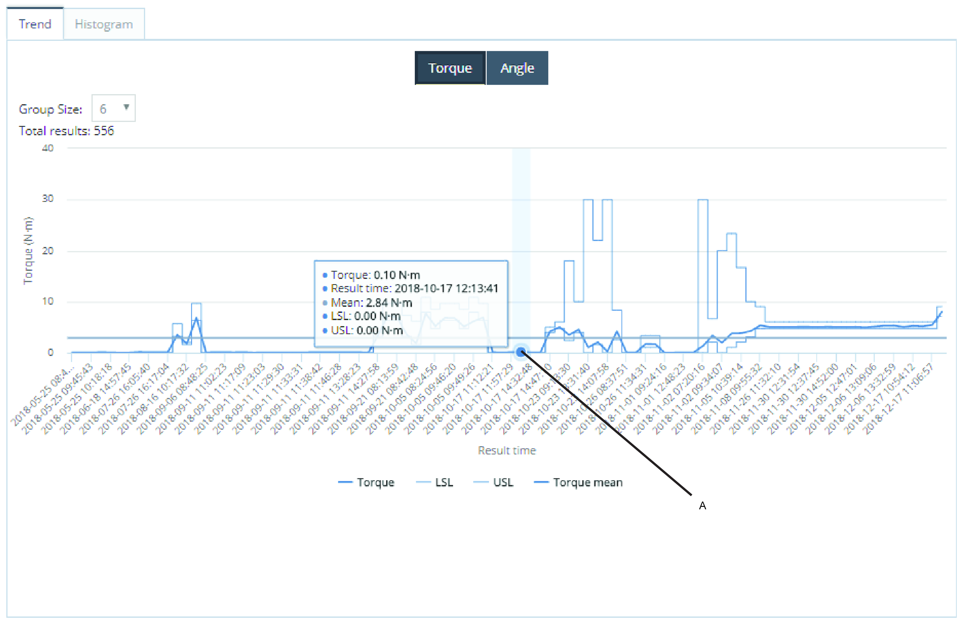
A | A group of 6 results with the average value of 0,10 Nm. |
Select one of the marked/unmarked Curve selection buttons to hide/show the selected curve.

Histogram Tab
Value buttons selecting X axis values (Torque/Angle), Value type default value is set to Torque.
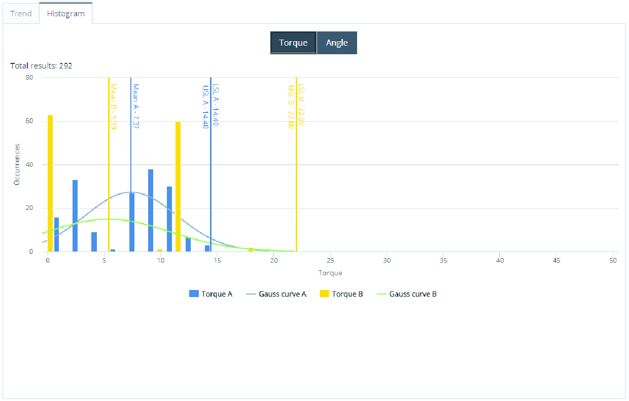
Select one of the marked/unmarked Curve selection buttons to hide/show the selected curve.
Working with the Notifications Tab
Notifications is a licensed feature that enables the system to send messages to the users, when events or trends are received from controllers connected to the system.
When an Event, Trend, Report or Alarm is received, the event information is converted into a standard email. The system can be configured to send relevant information to different work groups within the organization.
Product Essentials Tutorials
https://www.youtube.com/watch?v=xyoZ-GvwalY
Event Notifications
In the Notification wizard, Events, the configuration for event notifications is made. The configuration is created in four steps:
Event
Recipients
Rule information
Summary
When the configuration is made it is saved in the Saved Notifications table.
In the Notification wizard, Tool Structure selection box, select a tool.
In the Notification wizard event list, select event/ events and then select Next.
In the Notification wizard, Recipients list, select one or more of the check boxes for the email addresses for the email recipients, and then select Next.
Or Add a new email .
In the Notification wizard, Recipients, enter a new email address in the Add new email field and then select Add.
In the Notification wizard, Recipients list, select the check box for the new email address in the email recipients list, and then select Next.
In the Notification wizard, Rule information Name text field, name the notification.
In the Notification wizard, Rule information Comment text field, enter a comment and then select Next.
Summarizes your selections and select Finish.
Microvideo
SPC
Status alarms is used for the monitoring of statistical calculations in ToolsNet.
In the Notification wizard for Status Alarm, the user configures rules for the Status Alarm Notifications. The configuration is created in four steps:
SPC control limits
Recipients
Rule information
Summary
When the configuration is made it is saved in the Saved Notifications table.
Select a tool from the Tool structure.
Select a program.
Adjust SPC control limits manually or using the Calculate control limits button which calculates limits using variables from selected program. Select Group size if necessary. Select Status (All, OK, NOK).
Select Next.
In the Notification wizard, Recipients list, select one or more of the check boxes for the email addresses for the email recipients, and then select Next.
Or Add a new email .
In the Notification wizard, Recipients, enter a new email address in the Add new email field and then select Add.
In the Notification wizard, Recipients list, select the check box for the new email address in the email recipients list, and then select Next.
In the Notification wizard, Rule information Name text field, name the notification.
In the Notification wizard, Rule information Comment text field, enter a comment and then select Next.
Summarizes your selections and select Finish.
Trend Notifications
In the Notification wizard for Trends, the user configures rules for the Trend Notifications. The configuration is created in five steps:
Program
Thresholds
Recipients
Rule information
Summary
When the configuration is made it is saved in the Saved Notifications table.
In the Notification wizard, Tool Structure selection box, select a tool.
In the Notification wizard program list, select program/ programs and then select Next.
In the Notification wizard, Thresholds, select the check box for Interval, or Consecutive.
Use the threshold to enter the values to set up the notification rule.
Interval - Notification rule is based on number of NOK results within a specific time interval.
Consecutive - Notification rule is based on the number of consecutive NOK results.
In the Notification wizard, Thresholds, Threshold limit value selection box, enter the threshold limit for the number of NOK-results. When this amount of NOK-results is received, within the time limit specified below is reached, a notification will be sent. Or in the Consecutive limit selection, enter the number of consecutive NOK results.
In the Notification wizard, Thresholds, Threshold interval (minutes) value selection box, enter the number of minutes that should define the interval in which the NOK-results will be used to trigger the notification.
Select Next.
In the Notification wizard, Recipients list, select one or more of the check boxes for the email addresses for the email recipients, and then select Next.
Or Add a new email .
In the Notification wizard, Recipients, enter a new email address in the Add new email field and then select Add.
In the Notification wizard, Recipients list, select the check box for the new email address in the email recipients list, and then select Next.
In the Notification wizard, Rule information Name text field, name the notification.
In the Notification wizard, Rule information Comment text field, enter a comment and then select Next.
Summarizes your selections and select Finish.
Program Change Notifications
The program change notification will send a notification when a program version change has occurred.
In the Notification wizard for Program Change, the user configures the rules for Program Change Notifications. The configuration is created in four steps:
Tool structure
Recipients
Rule information
Summary
When the configuration is made it is saved in the Saved Notifications table.
In the Notification wizard, Tool Structure selection box, select a tool.
In the Notification wizard program list, select program/ programs and then select Next.
In the Notification wizard, Recipients list, select one or more of the check boxes for the email addresses for the email recipients, and then select Next.
Or Add a new email .
In the Notification wizard, Recipients, enter a new email address in the Add new email field and then select Add.
In the Notification wizard, Recipients list, select the check box for the new email address in the email recipients list, and then select Next.
In the Notification wizard, Rule information Name text field, name the notification.
In the Notification wizard, Rule information Comment text field, enter a comment and then select Next.
Summarizes your selections and select Finish.
Schedule Report Notifications
The Schedule Report in the Notification Center, is a is used to export the global favorites as an attached excel file, in a scheduled email.
In the Notification wizard for Schedule Report, the user configures rules for the Schedule Report Notifications. The configuration is created in five steps:
Choose favorite
Schedule
Recipients
Rule information
Summary
When the configuration is made it is saved in the Saved Notifications table.
In the Notification wizard > Choose favorite menu select one of the global favorites.
Select Next.
In the Start time calender, select a start date and start time, and then select Apply.
In the Hour frequency spin box, select frequency, and then select Next.
In the Notification wizard, Recipients list, select one or more of the check boxes for the email addresses for the email recipients, and then select Next.
Or Add a new email .
In the Notification wizard, Recipients, enter a new email address in the Add new email field and then select Add.
In the Notification wizard, Recipients list, select the check box for the new email address in the email recipients list, and then select Next.
In the Notification wizard, Rule information Name text field, name the notification.
In the Notification wizard, Rule information Comment text field, enter a comment and then select Next.
Summarizes your selections and select Finish.
Non Reporting Units Notifications
In the Notification wizard for Non Reporting Units, the user configures rules for the Non Reporting Units Notifications. The configuration is created in four steps:
Units
Recipients
Rule information
Summary
When the configuration is made it is saved in the Saved Notifications table.
In the Notification wizard, Units select Tool Structure, Weekdays, Start time and End time.
In the Notification wizard, Units select Threshold in hour and then select Next.
In the Notification wizard, Recipients list, select one or more of the check boxes for the email addresses for the email recipients, and then select Next.
Or Add a new email .
In the Notification wizard, Recipients, enter a new email address in the Add new email field and then select Add.
In the Notification wizard, Recipients list, select the check box for the new email address in the email recipients list, and then select Next.
In the Notification wizard, Rule information Name text field, name the notification.
In the Notification wizard, Rule information Comment text field, enter a comment and then select Next.
Summarizes your selections and select Finish.
Summarized Scheduled Report Notifications
Used for scheduling and specification of Non reporting units and Events notifications.
In the Notification wizard for Summarized Scheduled Report, the user configures rules for the Summarized Scheduled Report Notifications. The configuration is created in five steps:
Choose notifications
Schedule
Recipients
Rule information
Summary
When the configuration is made it is saved in the Saved Notifications table.
In the Notification wizard Tool structure list, select a tool.
In the Notification wizard tick the Program change checkbox .
In the Non reporting units manager, select tick boxes for Weekdays.
In the drop-down list box select Start time.
In the drop-down list box select End time
In the selection box select Threshold in hour, and then select OK.
In the Start time calender, select a start date and start time, and then select Apply.
In the Hour frequency spin box, select frequency, and then select Next.
In the Notification wizard, Recipients list, select one or more of the check boxes for the email addresses for the email recipients, and then select Next.
Or Add a new email .
In the Notification wizard, Recipients, enter a new email address in the Add new email field and then select Add.
In the Notification wizard, Recipients list, select the check box for the new email address in the email recipients list, and then select Next.
In the Notification wizard, Rule information Name text field, name the notification.
In the Notification wizard, Rule information Comment text field, enter a comment and then select Next.
Summarizes your selections and select Finish.
Box Analysis Notifications
In the Notification wizard for Box Analysis, the user configures rules for the Box Analysis Notifications. The configuration is created in four steps:
Choose favorite
Recipients
Rule information
Summary
When the configuration is made it is saved in the Saved Notifications table.
Box analysis will run in the background of the selected global favorite and notify when new tracks will hit the boxes.
An export, as an Excel™ file, is attached in the email for the favorite of your choice.
One or more global favorites must be selected in the User settings menu or saved as global favorites in Analysis Center > Box Analysis.
In the Notification wizard > Choose favorite menu select one of the global favorites.
Select Next.
In the Notification wizard, Recipients list, select one or more of the check boxes for the email addresses for the email recipients, and then select Next.
Or Add a new email .
In the Notification wizard, Recipients, enter a new email address in the Add new email field and then select Add.
In the Notification wizard, Recipients list, select the check box for the new email address in the email recipients list, and then select Next.
In the Notification wizard, Rule information Name text field, name the notification.
In the Notification wizard, Rule information Comment text field, enter a comment and then select Next.
Summarizes your selections and select Finish.
Units State Notifications
Expected Result:
In Units State notifications the user is able to receive a notification whenever a unit is connected or disconnected.
Example of received notification:
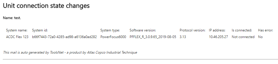
In the Notification wizard, Recipients list, select one or more of the check boxes for the email addresses for the email recipients, and then select Next.
Or Add a new email .
In the Notification wizard, Recipients, enter a new email address in the Add new email field and then select Add.
In the Notification wizard, Recipients list, select the check box for the new email address in the email recipients list, and then select Next.
In the Notification wizard, Rule information Name text field, name the notification.
In the Notification wizard, Rule information Comment text field, enter a comment and then select Next.
Summarizes your selections and select Finish.
Saved Notifications
In the Notifications tab, in the Saved notifications table all the configured notifications from all users are displayed. The table is sorted in types, the types can be expended using the expend button . The expended table shows all saved notifications for that specific type. The notifications are editable selecting the name or selecting the Edit button. The mail function can be tested selecting the Test Settings button. The saved notification can be removed using the Remove button.
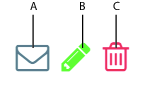
A | Test the email settings. |
B | Edit the notification settings. |
C | Remove the notification. |
Notifications
Notifications are used for keeping track of predefined actions and results. The notifications setup is made in the Notification wizard. All results are then gathered on the top menu bar.
On the top menu bar, select the Notifications button
 to display a limited selection of the latest notifications.
Select See All to list all the Notifications Results.
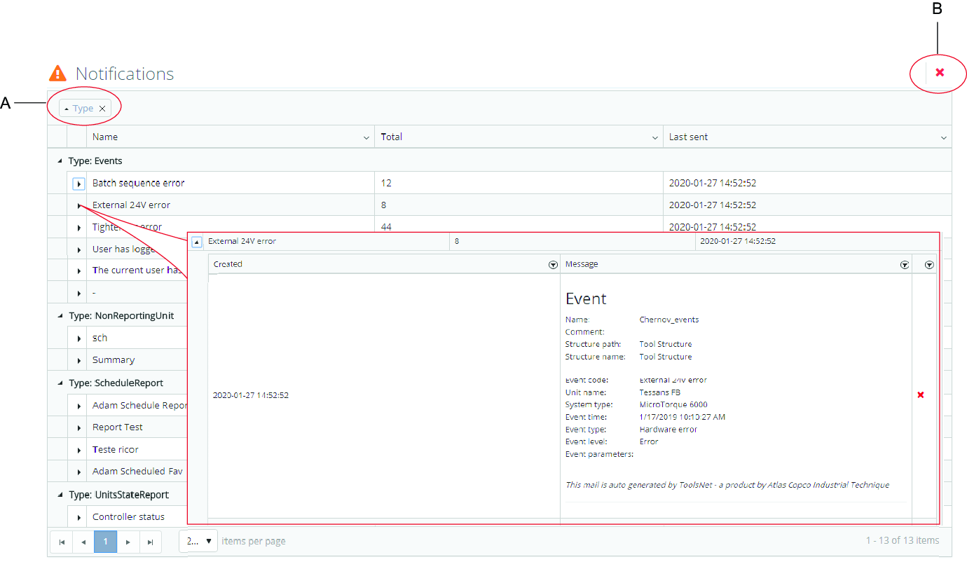
A | Sort order, (Type is default value) | B | Delete all button |
Select the Delete All button to delete all messages from the ToolsNet database.
This action does not affect the emails that were already sent to the respective recipients.
Select
to open a list of all messages sorted under a specific type.Select
again to open a detailed list of all messages sorted under a specific name.Select
 inside an opened message to delete the specific message.
This action does not affect the emails that were already sent to the respective recipients.
Working with the Tool Center Tab
The Tool Center is a licensed feature. The tools are listed in tabs depending on joining technology, Tightening, Press, Adhesive, Riveting. For each joining technology the tools are listed with changeable data columns. Information about each tool is displayed by using the expand button .
Adding a Tool
Add tool is used for manually adding tools.
Select Add tool.
Enter the relevant information in all the fields, and then select Save.
Microvideo
Using Filter in Tool Center
Use the Filter box to shorten the list of tools.
Use the Tool Structure list to filter among tool groups.
Microvideo
Comparing #Tightening since Service with Service Interval
Select a tab for Tightening, Press, Adhesive or Riveting.
Enter the Service Interval.
#Tightening since service - Service Interval ratio | Color |
|---|---|
Higher or equal to 100% | Red |
Higher or equal to 90%, lower than 100% | Yellow |
Below 90% | White |
Working with the Command Center Tab
The Command Center displays information about the running status of the application. The different Widgets display information from different parts of the application. These widgets are static and not configurable.
Displayed Widgets in Command Center
Data collection speed – Displays results per second for the results coming into the ToolsNet 8 database.
Data collection classic – Displays the connected controllers and received messages.
Service status – Displays the status of the ToolsNet 8 services.
Available Service Status:
Not installed (blue) – The system cannot recognize an installation of the service.
Start pending (yellow) – A service is starting up.
Started (green) – The service is running.
Stop pending (yellow) – A service is shutting down.
Stopped (red) – The service has stopped.
License status – Displays the extent of spindles defined by the license and the amount of consumed licenses. If the license server is restarted, a new count will be made out of connected units. Below is a list of the centers that are available by the license.
Unit monitoring – Displays the current distribution of connected, not connected and controllers with errors.
Maintenance log – Displays the logs and details of the delete maintenance jobs that have been run.
Database information – Displays basic information about the database.
Widgets can be expanded or collapsed by using the toggle arrow.
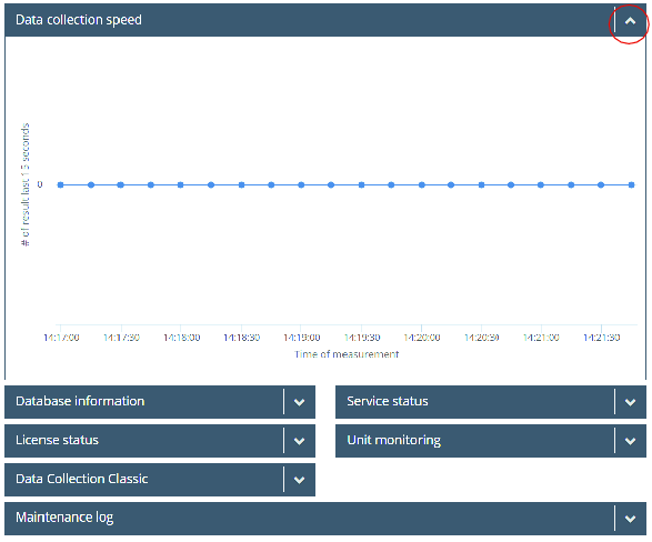
Database Information Widget
Contains database information, for example, information regarding:
Server name
Database name and size
Information about stored data and size
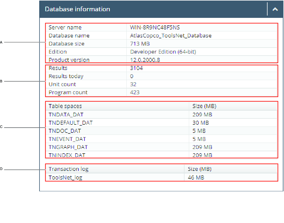
A | General information about the database engine | B | Summaries information from the DB |
C | Information about the size of the DB data files | D | Transaction log size |
Data Collection Speed Widget
Data Collection Speed – Displays the results per second for the results coming into the ToolsNet database.
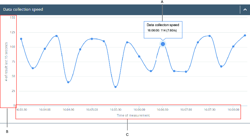
A | Data collection speed | B | Number of results during the last 15 seconds |
C | Time of measurement |
License Status Widget
License Status Widget – Displays the extent of spindles defined by the license and the amount of licenses consumed. If the license server is restarted, a new count will be made from the connected units. The list (C) displays the available centers for the license used.
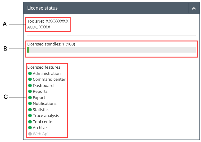
A | Shows the ToolsNet version, and the ACDC version, if ToolsNet is dependent on ACDC. | B | Shows the current number of accounted spindle licenses. This is not equivalent to the number of reporting spindles/units. |
C | Shows the available centers. |
Maintenance Log Widget
The Maintenance Log Widget displays the logs and details of the delete maintenance jobs that have been run. Each row displays the result of the maintenance activity. Select one of the Maintenance types to open the Maintenance details. Rearrange the table by selecting a column title and cycling through the sorting order options.
Example of activities that can be run by the system:
Index Reorganize – Reorganizing indexes in the database to improve performance. This does not affect any data.
Index Rebuild – Rebuilds the indexes in the database to improve performance. This does not affect any data.
Graphs maintenance – Graphs older than the specified “days to keep” value are deleted.
Event maintenance – Events older than the specified “days to keep” value are deleted.
Result maintenance – Results older than the specified “days to keep” value are deleted.
Program and unit maintenance – Programs and units older than the specified “days to keep” value are deleted.
Unit Monitoring Widget
Unit Monitoring Widget displays the current distribution of connected and not connected controllers and those with errors. If any controller has a faulty message in the controller queue, a red symbol is shown in the center of the doughnut chart. When selecting the center of the doughnut chart, a detailed table of the controllers is displayed. The detailed table shows information about the reporting controllers and their current status (Is connected and/or Has error). It is possible to expand a row for more details. If a controller has multiple errors, only the latest error is shown in the detailed table.
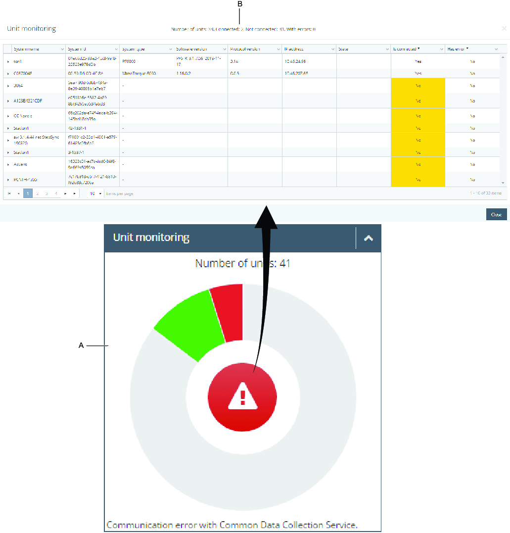
A | Doughnut chart | B | Detailed table |
Service Status Widget
Service Status Widget displays an overview of all available services and there status.
Available statuses are:
Running (Green) - The service is running
Not installed (Blue) – The system cannot recognize an installation of the service.
Start pending (Yellow) – A service is starting up.
Stop pending (Yellow) – A service is shutting down.
Stopped (Red) – The service is stopped.
Data Collection Classic Widget
Data Collection Classic Widget displays an overview of the message handling and number of connected controllers.
Overview
displays a collection of messages, but also total received and total committed messages.
Connected Controllers
displays program versions of the connected controllers.
Working with the Administration Tab
In the Administration Tab are the tools for managements for the programs, structures and shifts. The common function buttons for all the features in Administration Tab are the Add, Edit and Delete button.
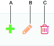
A | Add button | B | Edit button |
C | Delete button |
Group Administration (Admin only)
Members of the administration group using ToolsNet can access Group administration, in the Administration Tab. Here, roles can be connected to each center by entering a group name or SID.
Program Management
ToolsNet has a default structure called Tool structure. This structure is always available as an option in the reporting structure. Each controller is automatically connected to the Tool structure when it reports results to the system.
The list of available programs will only show the latest version of the program. Use the Tool structure to filter the list.
It is recommended to create separate custom structures, rather than changing the plant structure.
Program Classification
By classifying programs, they can be separated by the archiving job. The classifying decides how long results classified as Safety critical should be stored and if ordinary results should be stored. The storage of classified data is then dependent upon how the archiving job is configured on the database server.
Selections:
None
Safety critical
Quality critical
Creating a Reference Trace
Out of the 10 latest OK results, select a preferred trace as a reference. The selected trace will be the reference for all trace variants.
Select the + to select a specific program.
The Create reference trace window opens.

A | Create reference trace | B | View reference trace or remove reference trace |
When a reference trace is selected for a program, it will appear when viewing a trace of a result with the same program. In the trace view, it is possible to synchronize the result and the reference trace. The reference trace is shown with a dashed line.
Select a date or a custom time range, then select Apply.
Select a preferred trace as a reference.
Select Save.
Microvideo
Hiding a Program From The Nok Stats Widget and The Top Nok Report
It is possible to hide a programs from reports. Hiding a program can be useful when a program is no longer in use.
Select Administration and then select Program management.
In the Hidden column select the check box for the relevant program.
Managing Structures
Many reports in ToolsNet use a controller reporting group as one of the search filters. The controller groups can easily be defined for each plant and the concept allows reporting on summaries and trends based on customized structures for each plant.
Creating a Structure
In the Administration drop-down list, select the Manage structures.
In the Manage structures window, select the Create structure button.
In the Create structure text box, enter a name for the structure, and then select Save.
Microvideo
Creating a Folder
In the Manage structures window, select the Add folder button.
In the Folder name text box, enter a name for the folder, and then select Save.
Editing a Folder
In the Manage structures window, select the Edit folder button.
In the Folder name text box, edit the name for the folder, and then select Save.
Deleting a Folder
In the Manage structures window, select the Delete folder button.
On the Deleting folder - are you sure? command button, select Ok.
Drag and Drop a Unit
Drag and drop the unit into the selected folder.
To hide/see a unit, select the eye symbol (G) in the image below.
To remove a unit, select the x symbol (H) in the image below.
To move a unit to another location, drag and drop the unit into another folder.
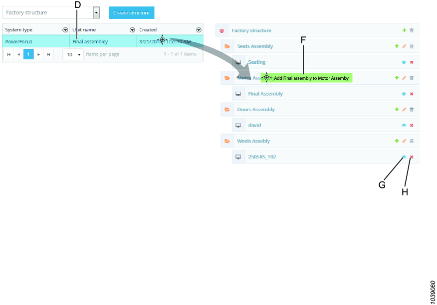
D | Unit list | F | Add unit to folder |
G | Hide/See unit | H | Remove unit |
Microvideo
Changing Ad-Group Association
Select the key symbol to change the ad-group associated with the Tool structure. This will make this specific Tool structure visible only to users within that group.
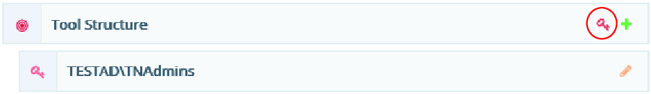
Show or Hide Unit
To show or hide a unit use the Hide Unit button  .
.
Managing Shifts
Shifts can be managed in Administration. It is possible to connect results to a certain shift as they are reported from the controller, by tagging new results with the shift.
In Reports, shift has been added as a criteria in Result, Result Summary and Top NOK reports. One shift can be a maximum of 24 hours and in Administration it is only possible to start a shift after today's date.
Adding a Shift
Select Add shift.
In the Shift menu, complete the following:
Enter a Name.
Enter a Description (optional).
Select a First occurrence start date and time for the shift.
Select a First occurrence end date and time for the shift.
Select an End date for the shift occurrence (The shift will continue for everyday until this date).
Select Save.
Editing a Shift
Select the green pen symbol to edit the shift settings.
Select Save.
Removing a Shift
Select the red trash can symbol to remove a shift (only possible if there is no data connected to the shift).
Select Ok.
Managing Units
Merge Unit Versions
Merge Unit Versions in the administration center is a function for merging different unit versions. This function is mostly used when the unit has changed name.
Merge versions results in:
The tools are not merged in the database.
Events and results from the merged units will appear in the remaining unit.
In the Administration drop-down list, select Manage units and then select Merge unit versions.
In the Select unit to merge window, select a unit containing versions in the tool structure and then select Next.
In the Select version to merge within unit window, select the check boxes for the versions to be merged, and then select Next.
In the Summary window, examine the units affected by the merge.
The following unit versions will be merged together.
The latest update of the unit versions will be the last remaining version.
Select Merge.
In the warning message, select OK to merge.
In the Merging units window, the remaining unit versions are displayed, select Close.
Creating Unit Links
In Create Unit Links the user is able to link two or more units (representing distinct physical units or virtual units). Linked units appear as one unit in the ToolsNet UI. When linking two or more units, one of the units is selected as the included unit and the other as the hidden unit. The data of the included unit will be data that is displayed for the linked unit in the ToolsNet UI. Hence, no data merge of the linked units are done.
It is only possible to create links between units using the same root in the tool structure.
See the outcome of linking units in the following example:
All results connected to the linked units will appear to be connected to the included unit. Only the included unit of the linked units will appear in the tool structure. When selecting an included unit in the tool structure, the results from all linked units will be part of the search.
Adding Unit Links
In the Administration drop-down list, select Manage units and then select Create unit links.
In the Select display unit window, select a unit to be displayed in the structure, and then select Next.
In the Select included unit(s) window, select the unit, or units, in the same root structure, and then select Next.
In the Summary window, check the displayed unit and the Included unit, and then select Finish.
Unlinking Unit Links
In the Administration drop-down list, select Manage units, and then select the unit links to unlink.
Select the Unlink button
 .
.
The user is able to unlink already linked units. When the previously linked units have been unlinked, they appear in the ToolsNet UI exactly as before the linking took place.
Managing Notification Service Settings
In order to get full functionality in the notification features, the Notification Service Settings has to be properly filled in.
On the Administration Tab, Settings in the Notification Service, enter the Email server settings.
Enable a SSL certificate if required.
Enter a Username and a Password.
Enter the Sender email, and then select Save or select Test settings to test the settings.
Managing Users
It is possible to remove any user in ToolsNet 8.
Removing Users
In Administration, Manage Users, select the red trash can to remove a specific user.
Using Filter
In Administration, Manage Users, input on the filter row the name of the user or email address for the search.
Reports and Statistics
In this section, you can learn about available reports and statistics.
Factors for Computing Control Chart Lines
Subgroup sample size, n | Factors for control limits | ||
|---|---|---|---|
X-bar chart | R-chart | ||
A2 | D3 | D4 | |
2 | 1.880 | - | 3.267 |
3 | 1.023 | - | 2.575 |
4 | 0.729 | - | 2.282 |
5 | 0.577 | - | 2.114 |
6 | 0.483 | - | 2.004 |
7 | 0.419 | 0.076 | 1.924 |
8 | 0.373 | 0.136 | 1.864 |
9 | 0.337 | 0.184 | 1.816 |
10 | 0.308 | 0.223 | 1.777 |
Symbols and Denominations
These are the symbols and denominations used in the software GUI.
Symbols | Description |
|---|---|
CL | Center line |
Cp | Process capability index |
Cpk | Minimum process capability index |
k | Number of subgroups |
LCL | Lower control limit |
LSL | Lower specification limit for the product |
n | Subgroup sample size |
N | Total number of observations |
R | Range of the subgroup observations: difference between the largest and smallest observed value |
Ṙ | Arithmetic average of the R values for the subgroups |
s | Sample standard deviation within the subgroup |
St | Sample (total/overall) standard deviation |
σ | Standard deviation for the population from which samples are taken |
σ̂ | Estimated standard deviation for the population from which samples are taken |
σt | Estimated (total/overall) standard deviation |
UCL | Upper control limit |
USL | Upper specification limit for the product |
X | Measured quality characteristic value, different observed values denoted with X1, X2 .., XN |
̅X̅ | Arithmetic average of subgroup sample observations |
̿X̿ | Total arithmetic average of the sample observations |
Control Charts in Toolsnet
The classical average (X bar or X̅) and range (R) control charts, where the average and range values are plotted in two diagrams for each subgroup sample, are included in ToolsNet. The method originally developed by Dr. Shewart of the Bell Telephone Laboratories is described in ISO 7870.
Troubleshooting and Service
This section provides assistance in troubleshooting problems, should they arise, and contains information to help you maintain and service the product.
(Installer) Error 1722. There Is a Problem with This Windows Installer Package
Cause: Internet Information Services is not activated or not running.
Solution: Prior to installation, check that Internet Information Services is running.
(Installer) Test Database Connection Fails
Cause: The Installer cannot connect to a database using the hostname, IP address, user name or password registered in the Setup dialog box.
Solution: Check the following:
The database account has Administrator rights.
The Administrator account is active.
(When using SQL Express) The instance name is entered in the Server Data Source field.
(Service Start) License Server Does not Start
Scenario A
Cause: Ports 6593-6395 are closed.
Solution: Open ports 6593-6395.
Scenario B
Cause: The Installation Number File is not saved.
Solution: As an Administrator, open License Registration and reload the Installation Number File received during Software Registration.
License Server needs Administrator rights to write data to the Windows Registry.
Scenario C
Cause: The license is registered to another Registration Number.
Solution: Register the license to the correct Registration Number.
(Service Start) Error 1075: Data Communication Service
Cause: MSMQ is not activated.
Solution: In Service Manager, activate Message Queuing under Add/Remove features.
(ToolsNet Web App) Signal R Error
Scenario A
Cause: Incorrect Active Directory security group configuration.
Solution: In web.config, set <authentication mode="None">.
Scenario B
Cause: The user is a member of too many Active Directory security groups.
Solution: Increase the MaxFieldLength and MaxRequestLength values in HKEY_LOCAL_MACHINE\System\CurrentControlSet\Services\HTTP\Parameters.
(ToolsNet Web App) Data Collection Speed Widget Is Empty
Cause: The Database Server does not allow any database jobs.
Solution: Do not use SQL Express.
ToolsNet 8 does not support SQL Express.
(ToolsNet Web App) Power Focus 4000, PowerMACS 4000 and ToolsNet OpenProtocol Controllers Are not Displayed in Unit Monitoring
Cause: Power Focus 4000, PowerMACS 4000 and ToolsNet OpenProtocol controllers are connected to the Data Collection Classic service.
Solution: View the Data Collection Classic widget, because Power Focus 4000, PowerMACS 4000 and ToolsNet OpenProtocol controllers are displayed there.
(ToolsNet Web App) ToolsNet Web App Does Not Launch and a "NullReferenceException: Object reference not set to an instance of an object" Occurs for Errors Relating to Get Session Facade
Cause: Internet Information Services (IIS) is not allowed to generate a session cookie.
Solution:
Open the Internet Information Services (IIS) Manager and navigate to Sites > Default Web Site > ToolsNet > Configuration Editor.
Under Section:, select system.web/sessionState and change the mode setting into InProc.
Restart the IIS service.
Reference
In this section, you can find miscellaneous useful information.
Reference Documents
Atlas Copco Documents
Document ID | Document name |
|---|---|
98391535 |