ILS Sensor
Positioning system
Product Information
General Information
Safety Signal Words
The safety signal words Danger, Warning, Caution, and Notice have the following meanings:
DANGER | DANGER indicates a hazardous situation which, if not avoided, will result in death or serious injury. |
WARNING | WARNING indicates a hazardous situation which, if not avoided, could result in death or serious injury. |
CAUTION | CAUTION, used with the safety alert symbol, indicates a hazardous situation which, if not avoided, could result in minor or moderate injury. |
NOTICE | NOTICE is used to address practices not related to personal injury. |
Warranty
Product warranty will expire 12+1 months after dispatch from Atlas Copco's Distribution Center.
Normal wear and tear on parts is not included within the warranty.
Normal wear and tear is that which requires a part change or other adjustment/overhaul during standard tools maintenance typical for that period (expressed in time, operation hours or otherwise).
The product warranty relies on the correct use, maintenance, and repair of the tool and its component parts.
Damage to parts that occurs as a result of inadequate maintenance or performed by parties other than Atlas Copco or their Certified Service Partners during the warranty period is not covered by the warranty.
To avoid damage or destruction of tool parts, service the tool according to the recommended maintenance schedules and follow the correct instructions.
Warranty repairs are only performed in Atlas Copco workshops or by Certified Service Partners.
Atlas Copco offers extended warranty and state of the art preventive maintenance through its ToolCover contracts. For further information contact your local Service representative.
For electrical motors:
Warranty will only apply when the electric motor has not been opened.
Website
Information concerning our Products, Accessories, Spare Parts and Published Matters can be found on the Atlas Copco website.
Please visit: www.atlascopco.com.
ServAid
ServAid is a portal that is continuously updated and contains Technical Information, such as:
Regulatory and Safety Information
Technical Data
Installation, Operation and Service Instructions
Spare Parts Lists
Accessories
Dimensional Drawings
Please visit: https://servaid.atlascopco.com.
For further Technical Information, please contact your local Atlas Copco representative.
Safety Data Sheets MSDS/SDS
The Safety Data Sheets describe the chemical products sold by Atlas Copco.
Please consult the Atlas Copco website for more information www.atlascopco.com/sds.
Country of Origin
For the Country of Origin, please refer to the information on the product label.
Dimensional Drawings
Dimensional Drawings can be found either in the Dimensional Drawings Archive, or on ServAid.
Please visit: http://webbox.atlascopco.com/webbox/dimdrw or https://servaid.atlascopco.com.
Overview
System Overview
The Atlas Copco's Industrial Location Guidance (ILG) is an integrated, stand-alone error proofing system that offers high-level process security for applications ranging from simple to complex.
ILG tracks the exact location of the tool relative to the fastening position, ensuring the correct fasteners are tightened to specification, in the proper sequence. Comprised of ILG software, positioning hardware (ILS Sensor) and tightening controller, the system combines the functionality of a tightening system with position and process control.
Monitors the location of the tool in the working area.
Guides the operator through the correct work sequence.
Automatically selects the tightening parameters for the position.
Ensures the correct fasteners are tightened to specification.
Unique P-Set selection for each position for full traceability.
The positioning hardware includes high precision rotary or linear position sensors that are integrated into the pivot joints or linear guides of a torque arm or similar applications. The sensors interface with the tightening controller or the Industrial PC via a gateway module. The gateway module communicates with the ILG service using Modbus TCP protocol. The ILG service communicates with the tightening controller through Open Protocol. Multiple Atlas Copco tightening controller models are compatible with the system and various positioning hardware configurations are available to suit the different arm types.
An ILG system consists of:
ILG software
Positioning hardware
Tightening controller
Industrial PC (optional /dependent on application)
The ILG service receives the data from the positioning hardware sensors to calculate the tool location in three-dimensional space, in real time. Once the tool is located in the specified position, the ILG service will select the tightening program (P-Set) and enable the tool through Open Protocol. Visual indicators, through a Stacklight, tool LEDs, or the HMI process screen, will alert the operator to initiate the tool start.
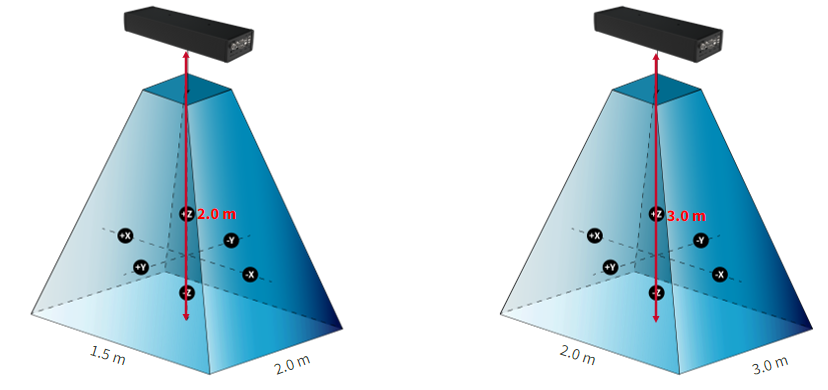
ILS Sensor
The ILS Sensor is a is a high-level, wireless line of site error proofing process security system and it consists of a sensor and a tag reflector.
The Receiver triangulates real-time position of the tool tag when visible within the coverage area and the sensor calculates the tag matrix position and generates (X,Y,Z) and (P,Y,R) location data values for the tag location. The tracking module sends information to ILG Software.
The ILG software validates the position and is used to enable or disable tool. Using Open protocol, it is provides position error proofing for bolt/process level operations.
ILS Sensors
There are two types of receivers based on the type of application:
ILS Sensor Standard
The standard ILS Sensor has a bolt accuracy of 10 mm and is used for standard applications.
ILS Sensor Wide
The wide ILS Sensor has a bolt accuracy of 20 mm and is used for bigger area coverage.
Structure of the Sensors
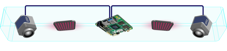
The ILS Sensor consists of two cameras, two infrared lighting units, and one computing unit.
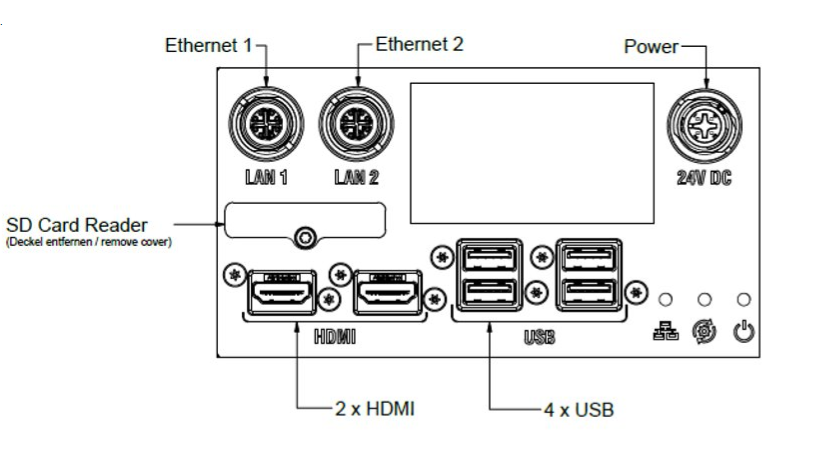
Connector Plate Overview
Item | Description |
|---|---|
LAN 1 | Ethernet connection for configurable IP address |
LAN 2 | Ethernet connection for fixed IP address (default 169.251.1.1) |
24V DC | Power inlet (135 W, 5.6 A) |
SD card | The SD card is used for storing settings, and transferring configurations between different ILS Sensors. |
HDMI | HDMI connections for displays |
USB | USB connections for keyboard, mouse, scanners, and other accessories |
Status Light Indications
The status lights on the connector plate for the sensor provide the following information:
Symbol | Status Light Color | Description | |
|---|---|---|---|
| Orange (blinking quickly) |
| |
Green (continuous light) | Ethernet cable connected to LAN1 port and Ethernet connection established, but Sensor tracking-software not running | ||
Red (blinking slowly) | Ethernet cable disconnected from LAN1 port and/or Ethernet connection could not be established | ||
| Black (no light) |
| |
Green (continuous light) | Sensor PC running, works normal | ||
Green (blinking) | Sensor PC in standby | ||
| Black (no light) |
| |
Green (continuous light) | Power On (24 V DC available) | ||


Cable Information
Power Cable
Power cable with standard raw cable, M12 4 pin open wires
Connector: female 4 pin M12 A-coded
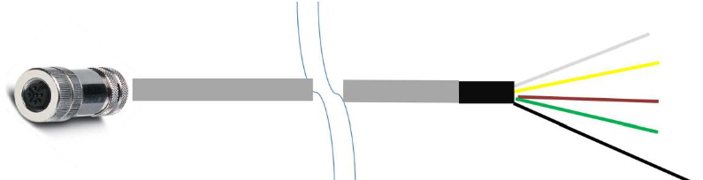
Side A | Wire Color | Side B | Function |
|---|---|---|---|
1 | White | Open wire | +24V |
2 | Yellow | Open wire | +24V |
3 | Brown | Open wire | GND |
4 | Green | Open wire | GND |
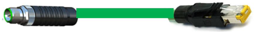
Ethernet Cable
Standard Ethernet cable, M12 x-coded for PoE+
Side A | Wire Color | Side B |
|---|---|---|
1 | Orange-white | 1 |
2 | Orange | 2 |
3 | Green-white | 3 |
4 | Green | 6 |
7 | Blue-white | 5 |
8 | Blue | 4 |
5 | Brown-white | 7 |
6 | Brown | 8 |
Product Data
Power | 135 W |
Rated voltage | 24 V |
Length | 921 mm |
Width | 171.6 mm |
Height | 84.6 mm |
Weight | 8.4 Kg/18.5lb |
Infrared light wavelength | 850 nm |
Service Overview
Service Recommendations
Preventive maintenance is recommended at regular intervals. See the detailed information on preventive maintenance. If the product is not working properly, take it out of service and inspect it.
If no detailed information about preventive maintenance is included, follow these general guidelines:
Clean appropriate parts accurately
Replace any defective or worn parts
Installation
Installation Instructions
General Installation Safety
Sensor must be mounted to station overhead or floor post, but must not be effected by any station vibrations or tooling movements that may cause alignment change.
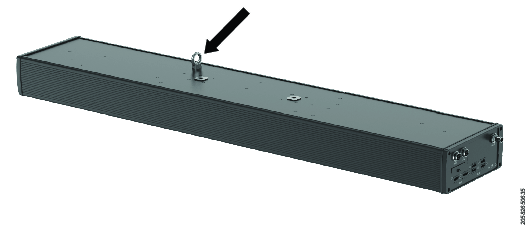
Installing the ILS Sensor
Before mounting the ILS Sensor, carefully consider the intended position. Keep in mind that the targets must always be visible to the cameras of the ILS Sensor.
Mount the ILS Sensor. Contact your local Atlas Copco representative for information on appropriate mounting brackets and installation instructions.
Connect the Ethernet cable to port LAN 1, or port LAN 2.

Port LAN 1 is configurable, while port LAN 2 uses a fixed IP address (default is 169.251.1.1).
Connect additional equipment, such as keyboard, mouse, scanner, and accessories, to the USB ports.
Connect monitor(s) to the HDMI ports.
Connect the 24V DC power supply cable to the 24V DC port (135 W, 5.6 A).
To setup and configure the ILS Sensor, refer to ILG Software User Guide.
Initial Configuration
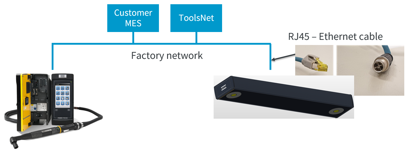
Controller Connection Options
The ILS Sensor can be connected to the controller in the following ways:
Via the controller's Factory Port. (Supported for Power Focus 6000, Power Focus 4000, and Power MACS controllers).
Via the controller's COM Port. (Only supported for Power Focus 6000 controllers).
Via the Factory Network. (Only supported for Power Focus 6000 controllers).
Connecting to the Controller via the Factory Port
When the ILS Sensor is connected to the controller's factory ethernet port, the controller can not be connected to the customers Factory Network.
Without Using Router or Ethernet Switch
Connect an Ethernet cable from the ILS Sensor's LAN 1 port to the factory Ethernet port of the controller.
Connect a second Ethernet cable from the ILS Sensor's LAN 2 port to an external PC.
Connect monitor, keyboard, mouse, and other accessories to the ILS Sensor's USB ports.
Check the IP settings of the controller.
Use the Remote Desktop Connection app to connect the external PC to the ILS Sensor. In the Remote Desktop Connection app, type in the name of the ILS Sensor:
ivne-xxxxxxxx , where xxxxxxxx is the serial number of the ILS Sensor (printed on the label on the connector plate).
Go to Control Panel > Network and Internet > Ethernet > Change adapter options > LAN 1 properties > Internet Protocol Version 4 > Properties.
Change the IP address for the ILS Sensor to the same IP-range as for the controller.
After finalizing the installation of ILG licenses the external PC can be disconnected from the workstation.
Using Router or Ethernet Switch
Connect an Ethernet cable from the ILS Sensor's LAN 1 port to the router.
Connect a second Ethernet cable from the controller's factory Ethernet port to the router.
Connect the external PC to the router.
Connect monitor, keyboard, mouse, and other accessories to the ILS Sensor's USB ports.
Check the IP settings of the controller.
Open a web browser and type the IP address of the controller's Factory Ethernet port.
Use the Remote Desktop Connection app to connect the external PC to the ILS Sensor. In the Remote Desktop Connection app, type in the name of the ILS Sensor:
ivne-xxxxxx , where xxxxxx is the serial number of the ILS Sensor (printed on the label at the connector plate).
Go to Control Panel > Network and Internet > Ethernet > Change adapter options > LAN 1 properties > Internet Protocol Version 4 > Properties.
Change the IP address of the ILS Sensor to the same IP-range as of the controller.
After finalizing the installation of ILG licenses the external PC can be disconnected from the workstation.
Connecting to the Controller via the COM Port
Without Using Router or Ethernet Switch
Connect an Ethernet cable from the ILS Sensor's LAN 1 port to the COM port of the controller, using the COM Port adapter, 4222 3073 00.
Connect a second Ethernet cable from the ILS Sensor's LAN 2 port to an external PC.
Connect monitor, keyboard, mouse, and other accessories to the ILS Sensor's USB ports.
Check the IP settings of the controller's service port. The default IP address is 169.254.1.1.
Use the Remote Desktop Connection app to connect the external PC to the ILS Sensor. In the Remote Desktop Connection app, type the name of the ILS Sensor:
ivne-xxxxxxxx , where xxxxxxxx is the serial number of the ILS Sensor (printed on the label of the connector plate).
Go to Control Panel > Network and Internet > Ethernet > Change adapter options > LAN 1 properties > Internet Protocol Version 4 > Properties.
Change the IP address of the ILS Sensor to the same IP-range as of the controller: 169.254.1.xxx.
The IP address in the ILG > Setup > Tools > Controller > IP must be the same in the PF > Settings > Network > IP address, in this case 169.254.1.1.
After finalizing the installation of ILG licenses the external PC can be disconnected from the workstation.
Connecting to the Controller via the Factory Network
Change the IP range of the ILS Sensor to the same IP range as of the controller.
When the ILS Sensor is using the Factory port the controller can not be connected to the Factory network.
Connecting to External PC using Windows Remote Desktop
Connect an Ethernet cable to the ILS Sensor's LAN 2 port. Connect the other end of the Ethernet cable to an external PC.
Power on the ILS Sensor.
Open the Remote Desktop Connection app on the external PC.
Type in ivne-xxxxxxxx (where xxxxxxxx is the name of the ILS Sensor), and select Connect.
The sensor's name is the serial number and can be found on the product label.
Type in the password (isra) in the login window, and select Yes.
The ILS Sensor and ILG Software run remotely on the external PC.
Operation
Ergonomic Guidelines
Consider your workstation as you read through this list of general ergonomic guidelines to identify areas for improvement in posture, component placement, or work environment.
Take frequent breaks and change work positions frequently.
Adapt the workstation area to your needs and the work task.
Adjust for a convenient reach range by determining where parts and tools need to be located to avoid static load.
Use workstation equipment such as tables and chairs appropriate for the work task.
Avoid work positions above shoulder level or with static holding during assembly operations.
When working above shoulder level, reduce the load on the static muscles by lowering the weight of the tool, using for example torque arms, hose reels or weight balancers. You can also reduce the load on the static muscles by holding the tool close to the body.
Take frequent breaks.
Avoid extreme arm or wrist postures, particularly during operations requiring a degree of force.
Adjust for a convenient field of vision that requires minimal eye and head movements.
Use appropriate lighting for the work task.
Select the appropriate tool for the work task.
In noisy environments, use ear protection equipment.
Use high-quality inserted tools and consumables to minimize exposure to excessive levels of vibration.
Minimize exposure to reaction forces.
When cutting:
A cut-off wheel can get stuck if the cut-off wheel is bent or not guided properly. Use the correct flange for the cut-off wheel and avoid bending the cut-off wheel during operation.
When drilling:
The drill might stall when the drill bit breaks through. Use support handles if the stall torque is high. The safety standard ISO11148 part 3 recommends using a device to absorb a reaction torque above 10 Nm for pistol grip tools and 4 Nm for straight tools.
When using direct-driven screwdrivers or nutrunners:
Reaction forces depend on the tool settings and joint characteristics. Strength and posture determine the amount of reaction force that an operator can tolerate. Adapt the torque setting to the operator's strength and posture and use a torque arm or reaction bar if the torque is too high.
In dusty environments, use a dust extraction system or wear a mouth protection mask.
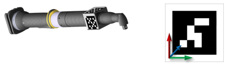
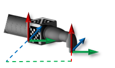
Localization of Targets
The sensors present in the ILS Sensor are used to localize the targets mounted on the manual tools.
Several targets can be present in the work space at the same time. The targets consist of one or more different tags.
The localization of targets includes the following steps:
Identify the tags.
Perform pose calculation for tags.
Obtain result of the pose calculation of tags.
Identifying the Tags
Every target is uniquely identifiable by one or more tags, which are applied to a specific manual tool. A tag is characterized by a specific pattern code and its specific tag ID. Each pattern code belongs to a set of available patterns.
Detection of Tags on Passive Targets
The passive tags consist of a base plate, a reflector, and a specific pattern.
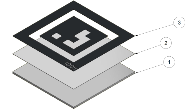
1 | Base Plate |
2 | Reflector |
3 | Specific Pattern |
The lighting unit of the sensor emits infrared light, which hits the reflector. The reflector reflects incident electromagnetic waves largely in the direction from which they came, regardless of the direction of incidence and the orientation of the reflector.
The substrate of the reflector consists of small transparent glass spheres, which focus most of the incident light.
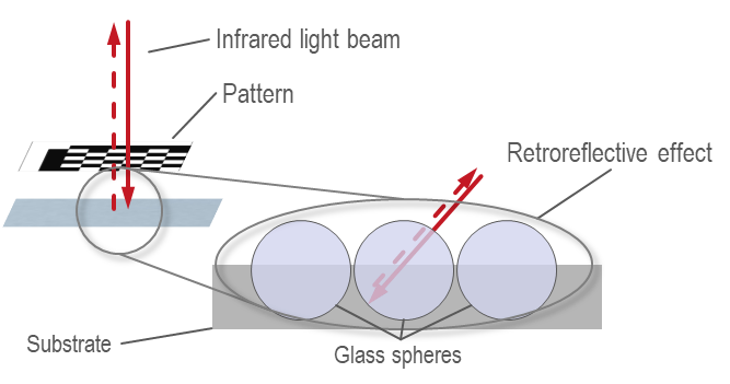
Due to the difference in the refractive index compared to air, the rear surface of the sphere is reflective. Due to this effect, the foil reflects the light back to the sensor. Each tag is defined by its specific pattern.
Performing Pose Calculation For Tags
With the stereo approach of two cameras, the 3D points of the tag are calculated from the corresponding tag corner points. The system determines the corners of the tag area in the image.
3D Result of Pose Calculation for Targets
Based on the pose(s) of the tag(s), the pose (position and orientation) of the target in the corresponding coordinate system is determined.
Service
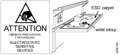
Preventing ESD Problems
The components inside the product and controller are sensitive to electrostatic discharge. To avoid future malfunction, make sure that service and maintenance is carried out in an ESD approved work environment. The figure below shows an example of an appropriate service work station.
Maintenance Instructions
Service Recommendations
Preventive maintenance is recommended at regular intervals. See the detailed information on preventive maintenance. If the product is not working properly, take it out of service and inspect it.
If no detailed information about preventive maintenance is included, follow these general guidelines:
Clean appropriate parts accurately
Replace any defective or worn parts
Recycling
Environmental Regulations
When a product has served its purpose it has to be recycled properly. Dismantle the product and recycle the components in accordance with local legislation.
Batteries shall be taken care of by your national battery recovery organization.