Install first FlexCarrier
Make sure the circuit breakers are off (down).
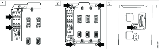
Fasten the FlexCarrier. Use M6 screws. Tighten at 9.8 Nm.
Use 4 screws for a 3 slot FlexCarrier.
Use 6 screws for a 6 slot FlexCarrier.
Set the FlexCarrier address.
The first FlexCarrier must be set to 1, the second to 2 etc. The default factory setting is 0. It is not allowed to have 0 as an address in an installed application. For more information on system planning, see FlexSystem System Overview Manual.
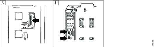
Select e-stop plug:
E-stop entry plug.
Advanced Security Module (ASM) plug.
Fasten the e-stop cables to the e-stop entry plug according to schematics. This step is not applicable for the ASM plug.
This is most easily done on a working bench.
Plug in the e-stop plug.
If the 24 VDC OUT and 24 VDC IN will be used, prepare the connectors.
This is most easily done on a working bench.
Install the 24 VDC IN/OUT connectors. Make sure you use the correct connector.
Do not connect the cables to the connector when the connector is fastened to the FlexCarrier.

If using an external 8 A power supply it shall be current limited to 8 A, double insulation. It shall be certified according to EN 61010-1 or according to another standard compatible with the requirements in EN 61010-1 (for example EN 60950 or EN 60601).
Route the cables through the gasket.
Make sure the cables are not pinched or damaged when the cover is put back on.
Do not route the cables so they block the LED light guide in the cover.