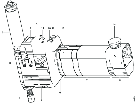
Main components and functions
Pos | Component | Function |
|---|---|---|
1 | Spindle | Main rotating part of the drill. |
2 | Spindle guard | Protects the operator from the rotating spindle. Provides the drill bit with coolant. |
3 | Head | Transfers rotational torque and feed from the motor to the spindle. |
4 | Feed cassette | Defines spindle feed rate. Measured in inches per revolution (IPR) or millimeters per revolution (mm/rev). |
5 | Air logic | Operates the drill. |
6 | Split gear | Defines rotational speed. Measured in revolutions per minute (RPM). |
7 | Motor housing | Supplies power and rotation to the spindle. Defines PRM range. |
8 | Motor valve | Supplies airflow to the turbine motor. |
9 | Counter | Counts number of drilled holes (optional). |
10 | Start button | Starts the motor and activates the drill feed and rotation mechanism. The motor continues to run after the button is released. When the spindle reaches the pre-defined drilling depth, it returns automatically to the starting position and the motor switches off. |
11 | Retract button | Returns the spindle to the starting position at any time during the drilling cycle. The motor switches off automatically after retract. |
12 | Release button | Releases the concentric collet foot or the indexer (air-powered front part). Applicable only if the front part is installed. |
13 | Pause button | Stops the drill momentarily. The drill cycle continues after pressing the start button. The pause button is also used when setting up the drill and the drill depth. |
14 | Emergency stop button | Switches off air supply to the motor and stops the spindle at any time during drilling cycle. Once pressed, the emergency stop button locks in position. Disconnects the drill from the air supply before you manually resets the emergency stop button. Connects the drill to the air supply and restarts the drill. |


