EP15PTX250 HR20-RE
Nutrunner
Product Information
General Information
Safety Signal Words
The safety signal words Danger, Warning, Caution, and Notice have the following meanings:
DANGER | DANGER indicates a hazardous situation which, if not avoided, will result in death or serious injury. |
WARNING | WARNING indicates a hazardous situation which, if not avoided, could result in death or serious injury. |
CAUTION | CAUTION, used with the safety alert symbol, indicates a hazardous situation which, if not avoided, could result in minor or moderate injury. |
NOTICE | NOTICE is used to address practices not related to personal injury. |
Warranty
Product warranty will expire 12+1 months after dispatch from Atlas Copco's Distribution Center.
Normal wear and tear on parts is not included within the warranty.
Normal wear and tear is that which requires a part change or other adjustment/overhaul during standard tools maintenance typical for that period (expressed in time, operation hours or otherwise).
The product warranty relies on the correct use, maintenance, and repair of the tool and its component parts.
Damage to parts that occurs as a result of inadequate maintenance or performed by parties other than Atlas Copco or their Certified Service Partners during the warranty period is not covered by the warranty.
To avoid damage or destruction of tool parts, service the tool according to the recommended maintenance schedules and follow the correct instructions.
Warranty repairs are only performed in Atlas Copco workshops or by Certified Service Partners.
Atlas Copco offers extended warranty and state of the art preventive maintenance through its ToolCover contracts. For further information contact your local Service representative.
For electrical motors:
Warranty will only apply when the electric motor has not been opened.
Website
Information concerning our Products, Accessories, Spare Parts and Published Matters can be found on the Atlas Copco website.
Please visit: www.atlascopco.com.
ServAid
ServAid is a portal that is continuously updated and contains Technical Information, such as:
Regulatory and Safety Information
Technical Data
Installation, Operation and Service Instructions
Spare Parts Lists
Accessories
Dimensional Drawings
Please visit: https://servaid.atlascopco.com.
For further Technical Information, please contact your local Atlas Copco representative.
Safety Data Sheets MSDS/SDS
The Safety Data Sheets describe the chemical products sold by Atlas Copco.
Please consult the Atlas Copco website for more information www.atlascopco.com/sds.
Country of Origin
For the Country of Origin, please refer to the information on the product label.
Dimensional Drawings
Dimensional Drawings can be found either in the Dimensional Drawings Archive, or on ServAid.
Please visit: http://webbox.atlascopco.com/webbox/dimdrw or https://servaid.atlascopco.com.
Overview
General Description
The Pistol ErgoPulse PTX shut-off tool is the ideal choice if your operators need to speed up production with fast rundowns and short tightening cycles. It is a reliable and powerful shut-off pulse tool that automatically shuts off the air supply when the pre-set torque has reached. Suitable for continuous heavy production, the PTX series has some air on top HRF models, making it possible to feed the air from above to the tool. All PTX models can also be used as lubrication free, just like other ErgoPulse tools and is available in StandardTrim and AutoTrim version.
Features
Consistent torque over time
Automatic two-stage trim valve
High power-to-weight ratio
No springs to wear out
High precision components
Benefits
High reliability and durability
One-handed operation
Light and well-balanced tool
Low noise level
Applications
This pneumatic shout-off impulse tool can be used for various applications where reaction free tightening and/or high productivity is needed.
Technical Product Data
Technical Product Data can be found on either ServAid, or the Atlas Copco website.
Please visit: https://servaid.atlascopco.com or www.atlascopco.com.
When to Use AutoTrim Valve or Trim Valve
AutoTrim Valve
For applications where the tool is used to tighten both hard and soft joints.
Trim Valve
For applications where the tool is used for tightening joints with similar characteristics.
Installation
Installation Requirements
Air Quality
For optimum performance and maximum product life we recommend the use of compressed air with a maximum dew point of +10°C (50°F). We also recommend to install an Atlas Copco refrigeration type air dryer.
Use a separate air filter which removes solid particles larger than 30 microns and more than 90% of liquid water. Install the filter as close as possible to the product and prior to any other air preparation units to avoid pressure drop.
For impulse/impact tools make sure to use lubricators adjusted for these tools. Regular lubricators will add too much oil and therefore decrease the tool performance due to too much oil in the motor.
Make sure that the hose and couplings are clean and free from dust before connecting to the tool.
Both lubricated and lubrication free products will benefit from a small quantity of oil supplied from a lubricator.
Air Lubrication Guide
Recommended air lubricators:
Atlas Copco Optimizer (1 liter) 9090 0000 04
Q8 Chopin 46
Shell Air Tool Oil S2 A 320
Compressed Air Connection
For correct air pressure and hose size, see the Technical Product Data on - https://servaid.atlascopco.com or www.atlascopco.com.
Make sure that the hose and couplings are clean and free from dust before connecting to the tool.
Air Pressure Regulation
A pressure regulator is recommended for each tool.
A pressure regulator will give the following advantages:
A stable air pressure which results in better accuracy
An easy way to adjust the power of the tool
Make sure to adjust the regulator to the lowest expected pressure on the line.
Adjusting the air pressure will have the following consequences:
Decreasing the air pressure will result in a slower but more accurate tool
Increasing the air pressure will result in a faster but less accurate tool
If the pressure from the airline is below five bar, a tool from the EP L-series (designed for low pressure installations) is recommended.
Installation Instructions
Installation of Vibrating Tools
We recommend using a minimum length of 300 mm (12") of flexible hose for compressed air between a vibrating tool and the quick-action coupling.
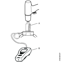
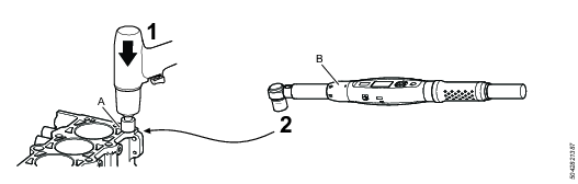
Initial Setting of Torque
To minimize the risk of damage to the actual joint we recommend to set the torque slightly lower on the test joint than the torque wanted for the application. Make sure to use the same equipment, such as for example extensions, sockets and air pressure on the test joint as will be used on the actual joint.
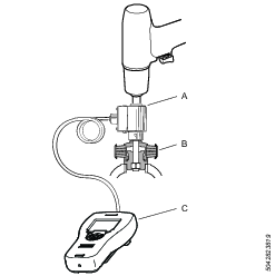
A | Torque transducer IRTT |
B | Test joint |
C | ST Analyzer |
Make sure to always verify the torque settings on your actual joint.
Operation
Ergonomic Guidelines
Consider your workstation as you read through this list of general ergonomic guidelines and see if you can identify areas for improvement in posture, component placement, or work environment.
Take frequent breaks and change work positions frequently.
Adapt the work area to your needs and the work task.
Adjust for convenient reach range by determining where parts or tools should be located to avoid static load.
Use workstation equipment such as tables and chairs appropriate for the work task.
Avoid work positions above shoulder level or with static holding during assembly operations.
When working above shoulder level, reduce the load on the static muscles by reducing the weight of the load. You can also reduce the load on the static muscles by holding the load close to the body.
Make sure to take frequent breaks.
Avoid extreme arm or wrist postures, particularly for operations requiring a degree of force.
Adjust for convenient field of vision by minimizing movement of the eyes and head during the work task.
Use the appropriate lighting for the work task.
Use ear protection equipment in noisy environments.
Use dust extraction system or mouth protection mask in dusty environments.
Operating Instructions
Air Pressure Monitoring, RE-signal
It is possible to connect the tool to a pressure monitoring equipment to monitor the tightening. The pressure signal from the tool (differential pressure over the motor) can be used to detect:
Missed fasteners
Trigger release before set torque is reached
Stripped threads
Cross-threading
Re-hits
Drop in air supply
To connect the tool to a pressure monitoring equipment we recommend using a Reporting Connection Kit, see Accessories https://servaid.atlascopco.com.
The pressure monitoring equipment does not measure torque.
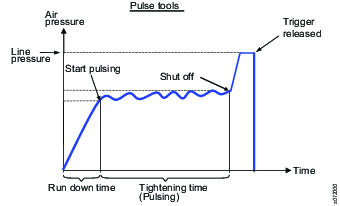
Air Pressure Signal Diagram
Optimizing the Tool Performance
Recommended number of pulses
A Pulse tool well suited for your application should reach the target torque (with shut off) within 5-20 pulses. The number of pulses it takes for the tool to reach target torque can be measured with an analyzer. The tightening time can also be used as a guide, to know if the tool is appropriate for your application:
≤ 1 second for tools up to 30 Nm
≈ 1 second for tools up to 80 Nm
≈ 2 seconds for tools up to 150 Nm
≈ 5 seconds for tools up to 450 Nm
≤ 10 seconds for tools up to 850 Nm
If the target torque is achieved with less than 5 pulses (= short tightening time), the torque scatter will increase and it can be difficult to adjust to the right level, especially on hard joints.
If the target torque is achieved with more than 20 pulses (= too long tightening time) the wear will increase and more frequent oil filling and service will be required. Too long tightening time, in combination with high production rate, may also result in excessive heating of the oil. In that case the power will decrease with longer tightening time and sometimes no shut off.
If the target torque is achieved with less than 5 pulses this can be fixed by:
Decreasing the air pressure.
Reducing the speed by means of the AutoTrim or Trim valve.
If the above is not possible or does not give wanted results, a smaller tool may be a better choice.
If the target torque is achieved with more than 20 pulses this can be fixed by:
Increasing the dynamic air pressure to 6-7 bar for standard EP tools, or up to 5 bar for low pressure EP L-tools.
Adjust the AutoTrim or Trim valve to give maximum power/speed.
If the above is not possible or does not give wanted results, a bigger tool may be a better choice.
When changing the air pressure, the target torque must be measured again and adjusted if needed.
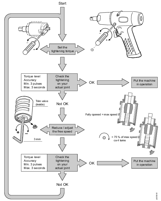
Setting the Tightening Torque Level - Trim-/RE-versions
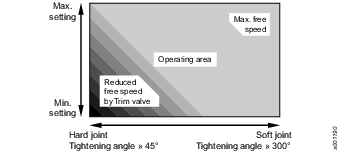
Operating Area
Tightening Time
The tightening time is depending on joint hardness. Hard joints give short operation time, and soft joints give longer operation time.
Max. recommended tightening time is 3 seconds. Longer time indicates that the joint is too soft for the machine used. If so it is recommended to choose a bigger size of machine or another type of nutrunner.
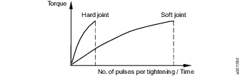
Pulses per Tightening
An increased number of pulses per tightening implies improved accuracy. Fewer pulses per tightening implies an increased scatter.
Min. recommended number of pulses per tightening is 3. Few pulses per tightening at a low setting indicates that the free speed ought to be reduced by the trim valve.
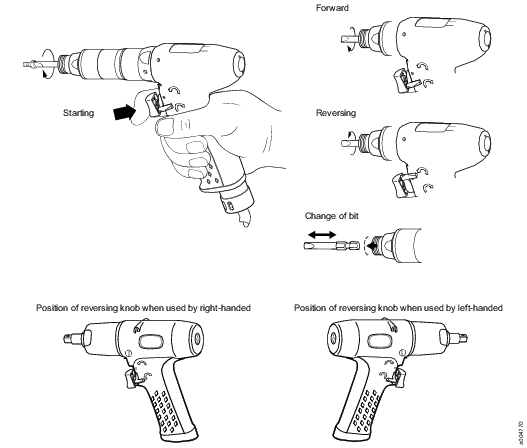
Operating the Tool
Free Speed Reduction
A reduced free speed implies improved accuracy and an increased number of pulses per tightening.
A reduced free speed may effect the torque level installed and the tightening time.
If the free speed is reduced, the number of pulses, as well as the torque level, will increase. After a reduction of the free speed the torque level might have to be reduced.

Setting of Tightening Torque
The adjusting screw (the slotted screw) is the only screw that initially should be adjusted. Start at a low torque adjustment and gradually increase the setting until you reach the desired torque level. See detailed illustrations for setting of the tightening torque when using AutoTrim function and Trim function respectively.
Using the tool at a higher torque, than recommended maximum torque, might result in improper function and faster wear.
Always check the setting on your actual joint.
Service
General Service Information
If the tool is not working properly, take it out of operation for inspection. Preventive maintenance is recommended at regular intervals. See detailed information on Preventive Maintenance.
Make sure to use the service tools, service kits and spare parts recommended by Atlas Copco.
Make sure to follow the Service instructions provided by Atlas Copco.
Make sure to work in a clean environment and that all parts are cleaned before re-assembling. Foreign particles, even small fibers from paper tissue, may affect the service life of the Pulse unit.
Maintenance Instructions
Preventive Maintenance
Preventive maintenance is recommended once per year or after a maximum of 250.000 tightenings. A complete overhaul include:
Clean the pulse unit and change worn or damaged parts.
Clean the air motor and change worn or damaged parts.
Clean the silencer and the strainer of the inlet adapter, change the filter and change worn or damaged parts.
Clean the trigger and reversing valve and change worn or damaged parts.
Service Instructions
Overhaul and preventive maintenance is recommended at regular intervals once per year or after maximum 250.000 tightening depending on which occurs sooner. More frequent overhaul may be needed, specially replacing of oil in the pulse unit, if used at high torque and long tightening times. If the machine is not working properly, it should immediately be taken away for inspection.
The strainer at the air inlet and the exhaust silencer should be cleaned frequently or replaced in order to prevent clogging, which decreases the capacity.
At the overhauls, all parts should be cleaned accurately and defective or worn parts should be replaced.
All o-rings should be greased before assembling; especially important are the o-rings in the pulse unit.
Dismantling/Assembling
It is important that threaded connections are tightened properly, that is, in accordance with the specifications. See Spare Parts for details.
Cleaning
Clean all parts (except electrical parts) thoroughly using white spirit or similar cleaning agent. To prevent clogging and decreased power, clean the strainer (if used) and the exhaust filter between the overhauls.
Inspection
After the cleaning, inspect all parts. Damaged and worn parts should be replaced.
Lubrication
Lubricate specially gears, valve and clutch with grease containing molybdenum disulphide (e.g. Molykote BR2 Plus). Lubricate o-rings and threaded connections with grease before assembling.
Daily Inspection
Make sure that the tool is in good condition, no visual damage.
Make sure that the air connection and air installation is done correctly. Listen for any air leakage.
Make sure that sockets and extensions have no visual damage.
Make sure to have the correct air pressure.
Listen to make sure that there is no unexpected noise when running the tool.
Lubrication Instructions
Rust Protection and Cleaning
Water in the compressed air can cause rust. To prevent rust we strongly recommend to install an air dryer.
Water and particles can cause sticking of vanes and valves. This can be prevented by installing an air filter close to the product to avoid pressure drop.
Before longer stand stills always protect your tool by adding a few drops of oil into the air inlet. Run the tool for 5–10 seconds and absorb any access oil at the air outlet in a cloth.
Lubrication Guide
Brand | General purpose, Bearings and Gears |
|---|---|
BP | Energrease LS-EP2 |
Castrol | OBEEn UF 1 |
Esso | Beacon EP2 |
Q8 | Rembrandt EP2 |
Mobil | Mobilegrease XHP 222 NLG 2 |
Klüber Lub. | Klübersynth UH 1 14-151 |
Texaco | Multifak EP2 |
Molykote | BR2 Plus |
Oil Level in the Pulse Unit
The right oil level in the Pulse unit is important for the tool to work correctly.
The need to add oil to the Pulse unit will vary depending mainly on the number of tightening, torque level and number of pulses (tightening time).
Operating the tool on a low oil level will result in faster wear of the parts in the Pulse unit. It will also affect the tool performance and accuracy.
Always check the tightening torque after filling the oil.
Detect Low Oil Level in the Pulse Unit
Longer tightening time
Very high pulse frequency, especially when the tool has not been used for a while.
Low torque or abnormal torque changes (increased scatter).
No shut-off.
To measure the pulse frequency use a static torque transducer or an inline transducer connected to torque testing equipment, as per the Tool Condition Test.
Recommended Oil for the Pulse Unit
The recommended oil for the pulse unit is Atlas Copco Pulse Unit Oil.
A bottle of Atlas Copco Pulse Unit Oil and the required syringe or syringes are orderable as kits. Please see Service Kits for ordering numbers.
Filling the Pulse Unit with Oil
There are different methods to fill the pulse unit with oil, depending on available equipment:
Using an ST Analyzer and a Transducer. Follow the instructions in Method 1.
This method is the fastest. It will give an optimized tool performance and result in the longest filling intervals.Without an ST Analyzer and a Transducer. Follow the instructions in Method 2.
This method is not as fast and accurate as using Method 1.Using the Atlas Copco Oil filling equipment kit (4250 3220 90). Follow the instructions in Method 3.
Method 1 (using an ST Analyzer and a Transducer)
Position the pulse unit in a vice. Remove the oil plug positioned on either the front (A) or the back (B) of the pulse unit. Add a small amount of oil to the pulse unit.
Assemble the tool and measure the pulse frequency.
If the pulse unit frequency is in the specified range the amount of oil is correct.
If the pulse unit frequency is too low reduce some oil and measure the pulse frequency again.
If the pulse frequency is to high add some oil and measure the pulse frequency again.
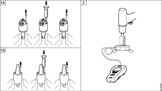
Model
Minimum free speed (r.p.m)
Pulse frequency (Hz)
Max Torque (minimum) (Nm)
EP15PTX250HR20-RE
3800
12-15
285
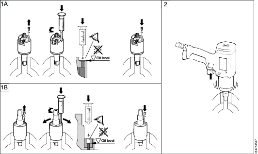
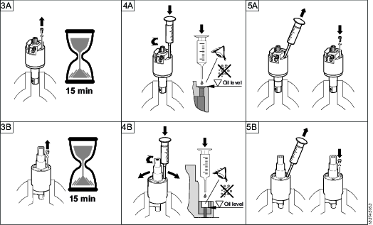
Method 2 (without ST Analyzer and Transducer)
Position the pulse unit in a vice. Remove the oil plug positioned on either the front (A) or the back (B) of the pulse unit. Fill the pulse unit to 100% full. Assemble the oil plug.
Assemble the tool and run in reverse for 3-5 seconds.
Position the pulse unit in a vice. Remove the oil plug. Wait for all air bubbles to disappear (approximately 15 minutes) and the temperature to drop down to 20 degrees.
Fill the pulse unit to 100% full.
Reduce the oil in the pulse unit with a specified volume according to table using a 1 ml syringe. Assemble the oil plug.
Oil volume to be
reduced from 100%
Approx. oil volume
in pulse-unit
2.3±0.05 ml
29 ml
Check torque and shut off function, for procedure see Testing/Measuring.
If everything is in order the amount of oil is right.
If everything is not in order repeat from step one.
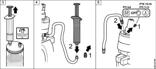
Method 3 (with Oil Filling Kit)
Required equipment for oil filling and oil changing:
Atlas Copco Pulse unit oil.
Atlas Copco Pulse unit Oil Filling Kit.
For ordering number for Spare Parts, see https://servaid.atlascopco.com.
Oil Filling Equipment Kit
2 x Adapter M3
2 x Adapter M4
4 x Hose length 540 mm
2 x Hose length 50 mm
1 x Hose length 120 mm
1 x Syringe 50 ml
1 x Syringe 1 ml
4 x Plug
5 x Connection
2 x Connection
2 x Can
2 x Cover
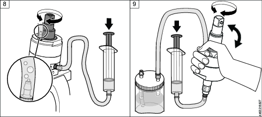
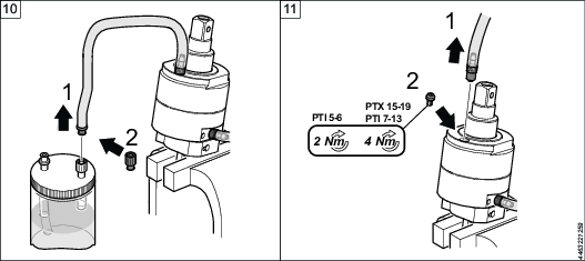
Place the Pulse unit in a vise at an angle so that the outlet hole is at the highest point.
Remove the screw covering the inlet opening. Make sure that the o-ring is on the screw and not left in the Pulse unit. Attach the filling hose by hand, with the hose connector end to the Pulse unit.
Fill the large syringe with oil to maximum capacity from the oil can.

Always use new Atlas Copco Pulse unit oil.
Remove the stop plug from the filling hose and then attach the syringe to the hose.
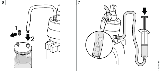
Remove the screw covering the outlet opening of the Pulse unit. Make sure that the o-ring is on the screw and not left in the Pulse unit. Attach the return hose to the Pulse unit.
Remove the stop plug from the return hose and then attach it to the oil can.
Start filling oil into the Pulse unit from the large syringe. When filling oil into the Pulse unit, there will be air bubbles exiting.
Rotate the anvil back and forth while filling the oil until no more bubbles are coming out of the Pulse unit.
Spin the complete Pulse unit around while filling the oil, to make sure that there are no air bubbles left inside of the Pulse unit.
Remove the return hose from the oil can and attach the stop plug to the return hose end.
Remove the return hose from the outlet opening of the Pulse unit. Put the screw covering the outlet opening back in position.
Now position the Pulse unit in the vise with the inlet opening facing upwards.
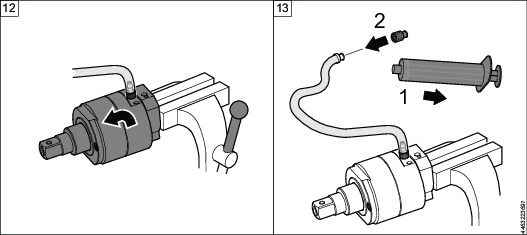
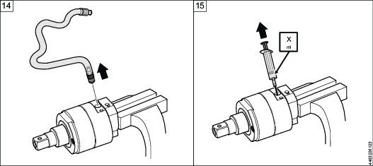
Remove the syringe from the filling hose and attach the stop plug to the filling hose.
Remove the oil filling hose from the Pulse unit.
Use the small syringe to extract the right amount of oil accordingly:
Oil reduction (X) from 100% full Pulse unit
Approximate oil volume in Pulse unit
2.3±0.05 ml
29 ml
Put the screw covering the inlet opening back in position.
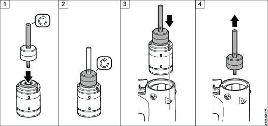
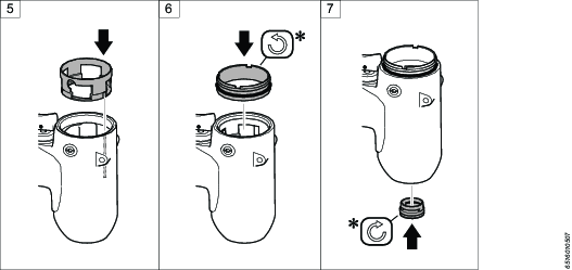
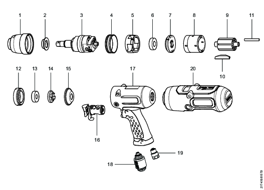
Dismantling/Assembling Instructions
Tightening of Threaded Connections
The tightening torque indicated in the exploded views (see Spare parts section in https://servaid.atlascopco.com) will give the right clamping force and prevent parts from loosening. It is important not to exceed the clamping force, these parts must be able to open up without being damaged at service. After some time of operation and in special circumstances, depending on application and usage, the parts may however loosen somewhat. The tightening torque can then be increased by 10-20% and some type of low or medium thread locking fluid can be applied.
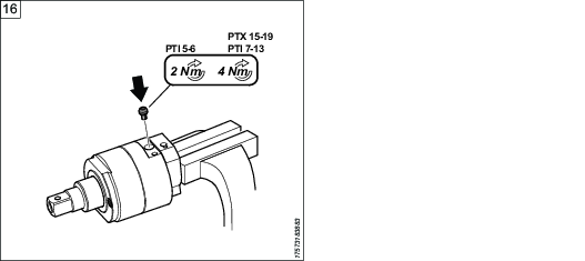
Assembling Motor in Housing
* For correct tightening torque, see Spare Parts https://servaid.atlascopco.com.
Tests and Adjustments after Service
Perform a tool condition test to make sure that the tool is working properly.
Test Method - Static or Dynamic
A static torque measurement is recommended for the ErgoPulse machines.
If dynamic torque measurement with an electronic inline torque transducer is used, always verify your measurement result by a static check with a torque wrench (electronic).
For more information, refer to Atlas Copco "Pocket Guide to Pulse Tools". Ordering No. 9833 1225 01.
Tool Condition Test
Test Conditions
Temperature Pulse unit: approximately 20° C.
Dynamic air pressure: 6.3 bar (91 psi).
Hose size: Ø 13 mm Hose length: 3 m
A | Static Torque transducer SRTT |
B | ST Analyzer (set at 850 Hz) |
Test the free speed in the forward direction with the tachometer.
Make sure that the tool runs on full speed regardless of AutoTrim or Trim setting. If the tool is used with AutoTrim, also test the AutoTrim function.
Test the maximum torque and pulse frequency by setting the filter frequency in ST Analyzer to 850 Hz.
Test the max torque and pulse frequency in reverse direction using an SRTT static torque transducer. Tightening time approximately 1 second.
Check the shut-off mechanism.
Perform some tightenings to make sure that the tool shuts off correctly.
A tool in good condition should achieve the following values:
Model | Free speed (rpm) | Pulse frequency CCW static (Hz) | Max Torque CCW static (minimum) (Nm) |
|---|---|---|---|
EP15PTX250 HR20-RE | 4300 -10%/+25% | 12-15 | 300 |
Correct pulse frequency indicates that the air motor and the Pulse unit are in good condition. If the pulse frequency is too high - add more oil. If the pulse frequency is too low - reduce the oil level.
Torque Check - Residual Torque Measurement on Actual Joint
Make sure to use the same equipment, such as extensions, sockets and air pressure during the tightening, as will be used on the actual tightening application.
When performing a torque check on the actual joint we recommend using an ST Wrench with residual torque measurement* setting.
* Torque required to cause the threads of the fastener (including its head) on which torque is applied, to move relative to the mating thread.
A | The actual joint |
B | Torque wrench with monitoring |
Perform a tightening.
Measure the result with the Torque wrench with monitoring.
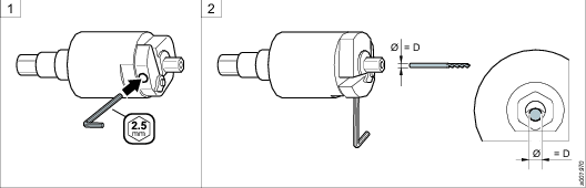
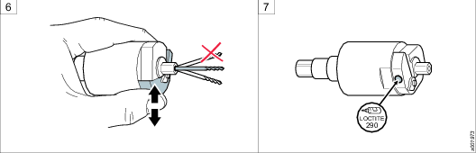
Adjusting the Position of the Stop Pin
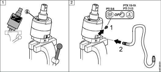
The position of the stop pin is correctly set at the factory. If the position has to be reset or adjusted due to service or replacement of spare parts, follow the instructions below.
Measurement D is the opening diameter for the gauge.
D = 1.55 mm
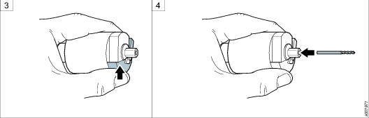
Fit a 2.5 mm Allen key in the adjustment screw.
Hold the Pulse unit with both stop surface of inertia body and anvil in horizontal position and the Allen key pointing downwards.
Press the inertia body to open the hole for the gauge.
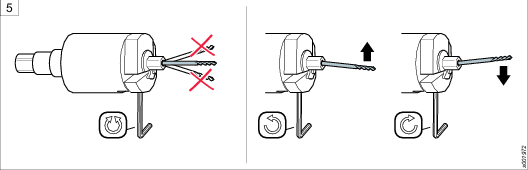
Place a gauge, for instance a drill bit, with the correct diameter of D in the hole.
Adjust the opening by turning the adjustment screw 45 degrees at the time until the gauge is in line with the pulse unit.
Avoid unnecessary turning of the adjustment screw.
Turn the screw anti-clockwise to raise the gauge.
Turn the screw clockwise to lower the gauge.
Check that the gauge is correctly inserted by repeatedly pressing and releasing the inertia body. The gauge should return to the correct position in line with the Pulse unit.
Apply Loctite 290 to the adjustment screw.
Troubleshooting
Troubleshooting - Trim / RE
Fault | Cause | Remedy |
|---|---|---|
The preset torque is decreasing and the pulse frequency is slightly increasing | Low oil level in the pulse unit? | Refill oil |
The machine does not reach the expected torque | Too soft joint ? The yield point of the joint’s screw has been reached ? | Operating area. A bigger machine? Check the torque adjustment and the joint’s screw quality |
The machine does not shut off | Air pressure at the machine too low ? Torque adjusting screw is set in a too deep position ? Stop pin is not correct ly adjusted ? Incorrect oil volume in pulse unit ? Too soft joint ? Too low rotary speed ? | Check the dimension of the hose and coupling, increase air pressure Adjust counter clockwise until the shut off is distinct Adjust according to the instruction
Refill oil
Choose a bigger machine Check the Trim valve setting, check the vane motor assembly |
Pulse frequency too low or too high | Incorrect oil volume in pulse unit ? | Refill oil |
Accuracy not as good as expected | Very hard joint and min. torque setting ? Too soft joint and max. torque setting ?
Stop pin is not correctly adjusted ? | Lower free speed by the Trim valve, Operating area Check the Trim valve setting. Choose a bigger machine, see Operating area Adjust according to the instructions. |
Recycling
Environmental Regulations
When a product has served its purpose it has to be recycled properly. Dismantle the product and recycle the components in accordance with local legislation.
Batteries shall be taken care of by your national battery recovery organization.
Recycling Instruction
Pos | Part | Remarks | Recycle as |
|---|---|---|---|
1 | Pulse unit casing | Metal, aluminum/steel | |
2 | Bushing | Metal, aluminum bronze | |
3 | Pulse unit | Metal, steel | |
4 | Screw ring | Metal, steel | |
5 | Sleeve | Metal, steel | |
6 | Ball bearing | Metal, steel | |
7 | End plate | Metal, aluminum | |
8 | Cylinder | Metal, aluminum | |
9 | Rotor | Metal, steel | |
10 | 7 vanes | Plastics, other, POM | |
11 | 7 plugs | Plastics, other, POM | |
12 | End plate | Metal, aluminum | |
13 | Ball bearing | Metal, steel | |
14 | Support washer | Metal, aluminum | |
15 | Inlet washer | Metal, aluminum | |
16 | Trigger | Metal, steel | |
17 | Motor casing | Metal, aluminum | |
18 | Silencer | Metal, steel | |
19 | Adapter | Metal, aluminum/steel | |
20 | Protective cover | Plastics, other, vinyl |