QMC21-12-OG
Electric screwdriver
Product Information
General Information
Power Tool Information
Safety Signal Words
The safety signal words Danger, Warning, Caution, and Notice have the following meanings:
DANGER | DANGER indicates a hazardous situation which, if not avoided, will result in death or serious injury. |
WARNING | WARNING indicates a hazardous situation which, if not avoided, could result in death or serious injury. |
CAUTION | CAUTION, used with the safety alert symbol, indicates a hazardous situation which, if not avoided, could result in minor or moderate injury. |
NOTICE | NOTICE is used to address practices not related to personal injury. |
Warranty
Product warranty will expire in 12+1 months after dispatch from Atlas Copco's Distribution Center.
Normal wear and tear on parts is not included within the warranty.
Normal wear and tear is that which requires a part change or other adjustment/overhaul during standard tool maintenance typical for that period (expressed in time, operation hours or otherwise).
The product warranty relies on the correct use, maintenance, and repair of the tool and its component parts.
Damage to parts that occurs as a result of inadequate maintenance or performed by parties other than Atlas Copco or their Certified Service Partners during the warranty period is not covered by the warranty.
To avoid damage or destruction of tool parts, service the tool according to the recommended maintenance schedules and follow the correct instructions.
Warranty repairs are performed only in Atlas Copco workshops or by Certified Service Partners.
Atlas Copco offers extended warranty and state-of-the-art preventive maintenance through its ToolCover contracts. For further information contact your local Service representative.
For electrical motors:
The warranty is valid only if the electric motor remains unopened.
Website
Information concerning our Products, Accessories, Spare Parts and Published Matters can be found on the Atlas Copco website.
Please visit: www.atlascopco.com.
ServAid
ServAid is a portal that is continuously updated and contains Technical Information, such as:
Regulatory and Safety Information
Technical Data
Installation, Operation and Service Instructions
Spare Parts Lists
Accessories
Dimensional Drawings
Please visit: https://servaid.atlascopco.com.
For further Technical Information, please contact your local Atlas Copco representative.
Safety Data Sheets MSDS/SDS
The Safety Data Sheets describe the chemical products sold by Atlas Copco.
Please consult the Atlas Copco website for more information www.atlascopco.com/sds.
Country of Origin
For the Country of Origin, please refer to the information on the product label.
Dimensional Drawings
Dimensional Drawings can be found either in the Dimensional Drawings Archive, or on ServAid.
Please visit: http://webbox.atlascopco.com/webbox/dimdrw or https://servaid.atlascopco.com.
Overview
Applications
The MicroTorque screw fastening systems are ultra low-torque applications.
Technical Product Data
Technical Product Data can be found on either ServAid, or the Atlas Copco website.
Please visit: https://servaid.atlascopco.com or www.atlascopco.com.
Installation
Installation Instructions
Installing the tool
For details, please refer to the dimensional drawings.
Mechanical installation
Attach the tool to the fixture in one of the following ways:

A: Using the holes of the tool base.
Four holes are intended for screws and two holes are intended for guide pins.
Electrical installation
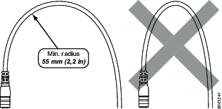
Connect the tool to the drive using the supplied cable.
Operation
Ergonomic Guidelines
Consider your workstation as you read through this list of general ergonomic guidelines to identify areas for improvement in posture, component placement, or work environment.
Take frequent breaks and change work positions frequently.
Adapt the workstation area to your needs and the work task.
Adjust for a convenient reach range by determining where parts and tools need to be located to avoid static load.
Use workstation equipment such as tables and chairs appropriate for the work task.
Avoid work positions above shoulder level or with static holding during assembly operations.
When working above shoulder level, reduce the load on the static muscles by lowering the weight of the tool, using for example torque arms, hose reels or weight balancers. You can also reduce the load on the static muscles by holding the tool close to the body.
Take frequent breaks.
Avoid extreme arm or wrist postures, particularly during operations requiring a degree of force.
Adjust for a convenient field of vision that requires minimal eye and head movements.
Use appropriate lighting for the work task.
Select the appropriate tool for the work task.
In noisy environments, use ear protection equipment.
Use high-quality inserted tools and consumables to minimize exposure to excessive levels of vibration.
Minimize exposure to reaction forces.
When cutting:
A cut-off wheel can get stuck if the cut-off wheel is bent or not guided properly. Use the correct flange for the cut-off wheel and avoid bending the cut-off wheel during operation.
When drilling:
The drill might stall when the drill bit breaks through. Use support handles if the stall torque is high. The safety standard ISO11148 part 3 recommends using a device to absorb a reaction torque above 10 Nm for pistol grip tools and 4 Nm for straight tools.
When using direct-driven screwdrivers or nutrunners:
Reaction forces depend on the tool settings and joint characteristics. Strength and posture determine the amount of reaction force that an operator can tolerate. Adapt the torque setting to the operator's strength and posture and use a torque arm or reaction bar if the torque is too high.
In dusty environments, use a dust extraction system or wear a mouth protection mask.
Operating Instructions
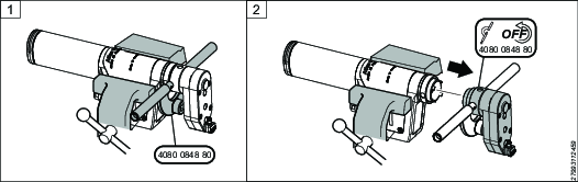
Mount Bit
Loosen the screw.
Open the locking arm.
Mount the bit.

Close the locking arm.
Tighten the screw.
Service
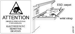
Preventing ESD Problems
The components inside the product and controller are sensitive to electrostatic discharge. To avoid future malfunction, make sure that service and maintenance is carried out in an ESD approved work environment. The figure below shows an example of an appropriate service work station.
Maintenance Instructions
Service Recommendations
Preventive maintenance is recommended at regular intervals. See the detailed information on preventive maintenance. If the product is not working properly, take it out of service and inspect it.
If no detailed information about preventive maintenance is included, follow these general guidelines:
Clean appropriate parts accurately
Replace any defective or worn parts
Preventive maintenance
Service should only be carried out by trained technician following provided service instructions and using original Atlas Copco spare parts.
The preventive maintenance intervals are based on the following definitions of use:
Tools are tested at their maximum torque. Operating at a lower target torque results in longer service intervals and reduced maintenance frequency.
The application is to assemble machine screws into metal threads. The typical run-down torque is below 15% of the target torque. Thread cutting or thread forming applications with high prevailing torque will reduce the service interval of the motor.
The tightening angle ranges from 30° (hard joint) to 720° (soft joint). The tightening angle is measured between seating and target torque. A higher tightening angle will reduce the service interval of the motor.
The highest possible speed for each torque level and joint characteristic is recommended. Lower speeds at high torque will reduce the service interval of the motor.
The feed force is limited by the axial load limitations of the ball bearings to a maximum of 80 N. A low feed force ensures good tightening accuracy and increases the service interval for the front part. High load and/or high-speed impacts to the front part can damage the ball bearings.
The vacuum pickup system will increase wear on the rubber sealings of the ball bearings, reducing the service interval for the front parts.
Tightening problems such as overshooting, stuck bits, and bit slip can reduce the service interval of the tool. These problems can be minimized by proper programming, using limits, and dividing the programming into several steps with different limits.
For more information about tightening strategies and troubleshooting, please refer to the configuration manual for ToolsTalk MT.
Interval | Action |
|---|---|
1.500.000 cycles or 1 year | Calibrate the tool |
1.500.000 cycles | Exchange front part |
3.000.000 cycles | Exchange motor |
500.000 cycles | Grease front part* |
*Grease gun 4080134700, Apply 0.13-0.17 g, grease 0017 1736 96
Lubrication Instructions
Lubrication
Lubricate according to the Lubrication Guide at each service occasion.
For more information, see Spare Parts section in ServAid - https://servaid.atlascopco.com.
Dismantling/Assembling Instructions
Dismantling the drive unit and the OG
Hold the spindle with a vise and the OG with an adjustable spanner.
Remove the OG from the spindle using the adjustable spanner.
Remove the spindle from the vise.
Remove the screw holding the cover, using a screwdriver.
Remove the cover.
Remove the two screws holding the housing, using an allen key.
Disconnect the indicator cable.
Move the cable out from the frame.
Remove the housing.
Disconnect the temperature sensor cable from the circuit board.
Move the cable out from the frame.
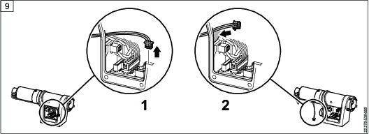
Disconnect the control cable from the circuit board.
Disconnect the motor cable from the circuit board.
Move the cable out from the frame.
Hold the spindle by the drive unit using a vise and an adjustable spanner.
Remove the ring nut and ring using an adjustable spanner.
Remove the spindle from the adjustable spanner.
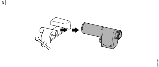
Remove the drive unit from the frame.
Lift the cable.
Take out the drive unit.


Assembling the drive unit and assembling and lubricating the OG
Insert the drive unit into the frame and connect the control cable to the circuit board.
Hold the spindle by the drive unit using a vise and an adjustable spanner.
Attach the locking pin and the ring, and tighten the ring nut using an adjustable spanner.
Remove the spindle from the adjustable spanner.
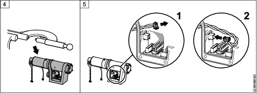
Thread the motor cable through the hole in the frame.
Connect the motor cable.
Thread the temperature sensor cable through the hole in the frame.
Connect the temperature sensor cable.
Attach the housing.
Thread the indicator cable through the hole in the frame
Connect the indicator cable.
Attach the two screws holding the housing, using an allen key
Attach the cover.
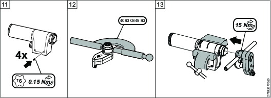
Mount the four screws holding the cover, using a screwdriver.
Hold the OG using an adjustable spanner.
Attach the OG to the spindle.

The adjustable spanner holds the OG and the vise holds the spindle.
Make sure the splines of the front part and the drive unit is aligned before attaching the front part. If the splines are not aligned mount a 1.5 hex bit to the front part and rotate the bit so the splines align.
Lubricate the OG by adding grease.


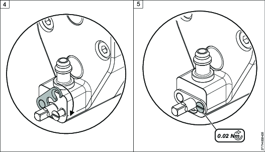
Replace Locking Arm
Remove the screw.
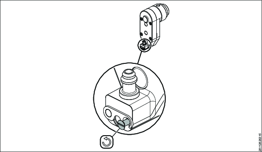
Remove the pin using a screwdriver.
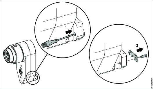
Install the pin.

Install the screw.

Recycling
Environmental Regulations
When a product has served its purpose it has to be recycled properly. Dismantle the product and recycle the components in accordance with local legislation.
Batteries shall be taken care of by your national battery recovery organization.
Recycling Information

Part No. | Part | Recycle as |
1 | Offset Gear | Metal, steel |
2 | Cap nut | Metal, steel |
3 | Cover ring | Plastics, other, TPU |
4 | Main board | Electronic |
5 | Motor | Electronic |
6 | Motor cover | Metal, aluminum |
7 | Drive unit without motor | Recycle as steel |
8 | Light electronics | Electronic |
9 | Lens | Plastics, other, PC |
10 | Light module housing | Metal, aluminum |
11 | Reflector | Plastics, other, POM |
12 | Part of light electronics | Electronic |
13 | Cover plate | Metal, stainless steel |
14 | Screws | Metal, stainless steel |
15 | Housing frame | Metal, aluminum |
16 | Screws | Metal, steel |