Tensioning Procedure
Procedure
Make sure that the two halves of the bolted joint are fully and correctly aligned.
Fit the hydraulic nuts to all of the stud bolts.
See section Hydraulic Nut System Configuration for configuration illustrations of hydraulic nut set up.
See section Hydraulic Nut Installation for installation instructions.
Make sure the pump is turned off and the pressure release valve is in the open position.
By using suitable link hoses, connect the hydraulic nuts together and to a suitable pump unit.

If simultaneous tensioning of more than one bolt is to be carried out, fit one male and one female quick connect coupling to each hydraulic nut, and by using link hoses, link each nut together. The end nut on the application should have either an unconnected female coupling (to a link hose) or a blanking plug.

Make sure the tensioning team is aware of the target working pressure.
Operate the pump unit and pressurize the system 1000 psi (70 bar). Make sure that the pressure is holding steady. If the pressure drops, investigate the problem by looking for leaks. For pump operation, see the Product Instructions for the pump.

Never exceed the maximum working pressure.

Never leave high pressure hydraulic tools unattended while pressurized.

The system must be at zero pressure before starting any investigation, maintenance or leak repair work.

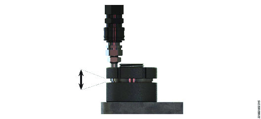
Maximum stroke is indicated with the red line above the threads on the piston.

Never exceed the maximum piston stroke capability of the tensioning tool.
If the maximum stroke indicator appears on any of the tools before the target operating pressure is reached, immediately stop the pressurization sequence. Slowly open the pump pressure release valve and make sure that the pressure drops to zero. Return the body and restart the tensioning procedure.

When the pressure is holding steady, continue to pressurize the system up to the target calculated working pressure.
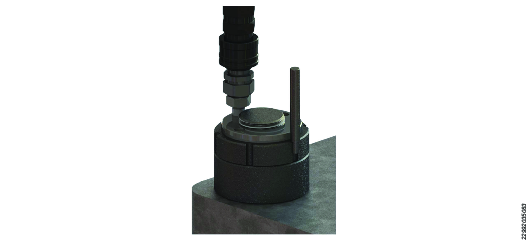
When the required pressure is achieved, hold the pressure. To retain the bolt load, firmly tighten the load retaining collar down against the nut body, with the tommy bar and a mallet.

In order to retain enough preload, the load collar must be firmly seated.

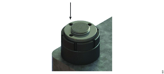
When the collar is seated properly down against the top face of the load cell body, the piston of the hydraulic nut is clearly visible above the collar.

Release the pump pressure.
Remove the hydraulic link hose from the hydraulic nut.

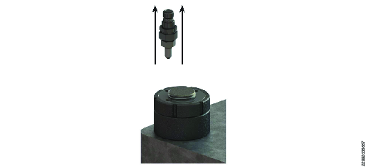
Unscrew and remove the hydraulic connection.
Replace the original blanking plug to prevent the ingress of contaminants into the internals of the hydraulic nut.

Hydraulic couplers of either type must be tightened into the tool from the adaptor piece only. Required tightening torque is 25Nm.


