EM Stop Connector Configurations
The following EM Stop connector configurations are possible:
EM Stop default configuration (no EM Stop connected).
EM Stop entry configuration - single controller with hand-held tools.
EM Stop entry configuration - multiple controllers with hand-held tools.
EM Stop entry configuration - single controller with fixtured tools.
EM Stop entry configuration - multiple controllers with fixtured tools.
EM Stop entry configuration - single controller without manual reset.
EM Stop bypass configuration.
EM Stop loopback configuration.
EM Stop Default Configuration
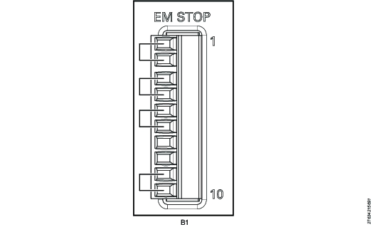
The POWER FOCUS 8 comes with preinstalled jumpers for this configuration.
Use the following pin configuration:
Pin | Pin name | Use |
|---|---|---|
1 | EM_NC1 | Connect a jumper between pin 1 and pin 2 |
2 | EM_STOP+ | See pin 1 |
3 | EM_STOP+ | Connect a jumper between pin 3 and pin 4 |
4 | 24V_ISOL_EXT | See pin 3 |
5 | EM_STOP- | Connect a jumper between pin 5 and pin 6 |
6 | GND | See pin 5 |
7 | EM_BYPASS_STOP- | Do not use |
8 | EM_BYPASS_NC | Do not use |
9 | EM_RESET_IN | Connect a jumper between pin 9 and pin 10 |
10 | EM_NC2 | See pin 9 |
EM Stop Entry Configuration - Single Controller with Hand-held Tools
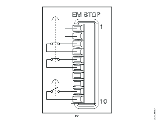
EM Stop button connector: Phoenix, 10-pin headers, 3.5 mm pitch
Use the following pin configuration:
Pin | Pin name | Use |
|---|---|---|
1 | EM_NC1 | Connect a jumper between pin 1 and pin 2 |
2 | EM_STOP+ | See pin 1 |
3 | EM_STOP+ | Connect an emergency button between pin 3 and pin 4 |
4 | 24V_ISOL_EXT | See pin 3 |
5 | EM_STOP- | Connect an emergency button between pin 5 and pin 6 |
6 | GND | See pin 5 |
7 | EM_BYPASS_STOP- | Do not use |
8 | EM_BYPASS_NC | Do not use |
9 | EM_RESET_IN | Connect a reset button between pin 9 and 10 |
10 | EM_NC2 | See pin 9 |
EM Stop Entry Configuration - Multiple Controllers with Hand-held Tools
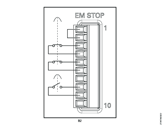
Pin | Pin name | Use |
|---|---|---|
1 | EM_NC1 | Connect a jumper between pin 1 and pin 2 |
2 | EM_STOP+ | See pin 1 |
3 | EM_STOP+ | Connect an emergency button between pin 3 and pin 4 |
4 | 24V_ISOL_EXT | See pin 3 |
5 | EM_STOP- | Connect an emergency button between pin 5 and pin 6 |
6 | GND | See pin 5 |
7 | EM_BYPASS_STOP- | Do not use |
8 | EM_BYPASS_NC | Connect a reset button between pin 8 and 9 |
9 | EM_RESET_IN | See pin 8 |
10 | EM_NC2 | Do not use |
EM Stop Entry Configuration - Single Controller with Fixtured Tools
For this configuration, the remote start enable switch must be set to ON.
Pin | Pin name | Use |
|---|---|---|
1 | EM_NC1 | Connect a jumper between pin 1 and pin 2 |
2 | EM_STOP+ | See pin 1 |
3 | EM_STOP+ | Connect an emergency button between pin 3 and pin 4 |
4 | 24V_ISOL_EXT | See pin 3 |
5 | EM_STOP- | Connect an emergency button between pin 5 and pin 6 |
6 | GND | See pin 5 |
7 | EM_BYPASS_STOP- | Do not use |
8 | EM_BYPASS_NC | Do not use |
9 | EM_RESET_IN | Connect a reset button between pin 9 and 10 |
10 | EM_NC2 | See pin 9 |
EM Stop Entry Configuration - Multiple Controllers with Fixtured Tools
For this configuration, the remote start enable switch must be set to ON.
Pin | Pin name | Use |
|---|---|---|
1 | EM_NC1 | Connect a jumper between pin 1 and pin 2 |
2 | EM_STOP+ | See pin 1 |
3 | EM_STOP+ | Connect an emergency button between pin 3 and pin 4 |
4 | 24V_ISOL_EXT | See pin 3 |
5 | EM_STOP- | Connect an emergency button between pin 5 and pin 6 |
6 | GND | See pin 5 |
7 | EM_BYPASS_STOP- | Do not use |
8 | EM_BYPASS_NC | Connect a reset button between pin 8 and 9 |
9 | EM_RESET_IN | See pin 8 |
10 | EM_NC2 | Do not use |
EM Stop Entry Configuration - Single Controller without Manual Reset
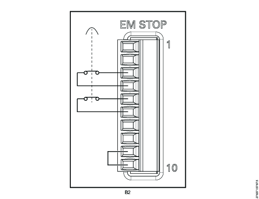
EM Stop button connector: Phoenix, 10-pin headers, 3.5 mm pitch
Use the following pin configuration:
Pin | Pin name | Use |
|---|---|---|
1 | EM_NC1 | Do not use |
2 | EM_STOP+ | Do not use |
3 | EM_STOP+ | Connect an emergency button between pin 3 and pin 4 |
4 | 24V_ISOL_EXT | See pin 3 |
5 | EM_STOP- | Connect an emergency button between pin 5 and pin 6 |
6 | GND | See pin 5 |
7 | EM_BYPASS_STOP- | Do not use |
8 | EM_BYPASS_NC | Do not use |
9 | EM_RESET_IN | Connect a jumper between pin 9 and pin 10 |
10 | EM_NC2 | See pin 9 |
EM Stop Bypass Configuration
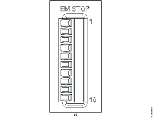
EM Stop I/O cable connector: Phoenix, 10-pin
Remove plug or use the following pin configuration:
Pin | Pin name | Use |
|---|---|---|
1 | EM_NC1 | Do not use |
2 | EM_STOP+ | Do not use |
3 | EM_STOP+ | Do not use |
4 | 24V_ISOL_EXT | Do not use |
5 | EM_STOP- | Do not use |
6 | GND | Do not use |
7 | EM_BYPASS_STOP- | Do not use |
8 | EM_BYPASS_NC | Do not use |
9 | EM_RESET_IN | Do not use |
10 | EM_NC2 | Do not use |
EM Stop loopback configuration
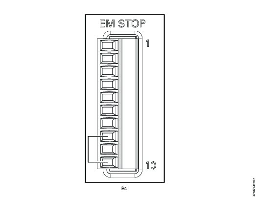
EM Stop I/O cable connector: Phoenix, 10-pin
Use the following pin configuration:
Pin | Pin name | Use |
|---|---|---|
1 | EM_NC1 | Do not use |
2 | EM_STOP+ | Do not use |
3 | EM_STOP+ | Do not use |
4 | 24V_ISOL_EXT | Do not use |
5 | EM_STOP- | Do not use |
6 | GND | Do not use |
7 | EM_BYPASS_STOP- | Do not use |
8 | EM_BYPASS_NC | Connect a jumper between pin 8 and pin 10 |
9 | EM_RESET_IN | Do not use |
10 | EM_NC2 | See pin 8 |


