EM Stop Connection Scenarios
The following connection scenarios are possible:
Scenario 1 - No EM Stop, single controller with its remote start enable switch set to OFF.
Scenario 2 - EM Stop, single controller with its remote start enable switch set to ON and used with fixtured tools.
Scenario 3 - EM Stop, single controller with its remote start enable switch set to OFF and used with hand-held tools.
Scenario 4 - EM Stop, multiple controllers with their remote start enable switches set to ON and using a reset button.
Scenario 5 - EM Stop, multiple controllers with their remote start enable switches set to OFF and using software reset.
Scenario 1 - No EM Stop, single controller with its remote start enable switch set to OFF
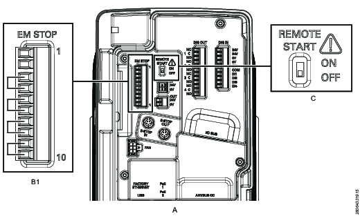
A | Controller |
B1 | EM Stop default configuration |
C | Remote start enable switch set to OFF |
In this scenario, no EM Stop is used. The corded tools tool trigger acts as the safety device. The remote start enable switch on the connector board is set to OFF. The EM Stop connector requires the default or no EM Stop configuration. This is the EM Stop connector configuration that the controller is shipped with.
Scenario 2 - EM Stop, single controller with its remote start enable switch set to ON and used with fixtured tools
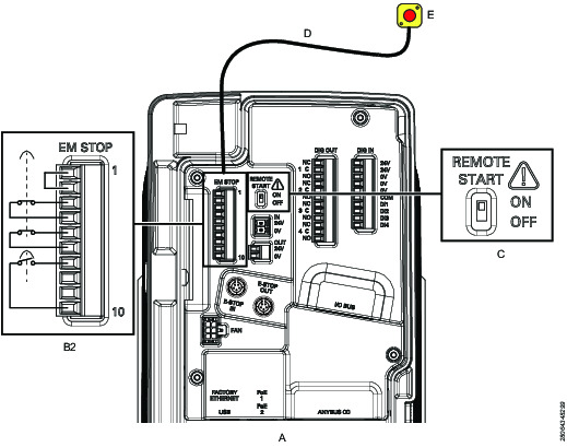
A | Controller |
B2 | EM Stop entry configuration |
C | Remote start enable switch set to ON |
D | EM Stop button cable connected to EM Stop connector |
E | EM Stop button |
In this scenario, an EM Stop is used with a single controller. The remote start enable switch on the connector board is set to ON. The EM Stop connector requires the B2 EM Stop entry configuration.
Scenario 3 - EM Stop, single controller with its remote start enable switch set to OFF and used with hand-held tools

A | Controller |
B2 | EM Stop entry configuration |
C | Remote start enable switch set to OFF |
D | EM Stop button cable connected to EM Stop connector |
E | EM Stop button |
In this scenario, an EM Stop is used with a single controller. The remote start enable switch on the connector board is set to OFF. The EM Stop connector requires the B2 EM Stop entry configuration.
Scenario 4 - EM Stop, multiple controllers with their remote start enable switches set to ON and using a reset button

A1 | First controller |
A2 | Intermediate controller |
A3 | Last controller |
B2 | EM Stop entry configuration |
B3 | EM Stop bypass configuration |
B4 | EM Stop loopback configuration |
C | Remote start enable switch set to ON |
D | EM Stop button cable connected to EM Stop connector |
E | EM Stop button |
F | I/O cables connected between E-STOP IN and E-STOP OUT |
G | Ethernet cables connected between PoE ports |
In this scenario, an EM Stop is used with multiple controllers that are interconnected with I/O cables and RJ45 Ethernet cables. The I/O cables are connected to the E-STOP IN and E-STOP OUT connectors as shown above. The RJ45 Ethernet cables are connected to the PoE ports (PoE 1, PoE 2). For each controller, the remote start enable switch on the connector board is set to ON. The EM Stop connector configuration depends on the controller location within the chain:
For the first controller, the EM Stop connector requires the entry configuration.
For any intermediate controller, the EM Stop connector requires the bypass configuration.
For the last controller, the EM Stop connector requires the loopback configuration.
Scenario 5 - EM Stop, multiple controllers with their remote start enable switches set to OFF and using software reset

A1 | First controller |
A2 | Intermediate controller |
A3 | Last controller |
B2 | EM Stop entry configuration |
B3 | EM Stop bypass configuration |
B4 | EM Stop loopback configuration |
C | Remote start enable switch set to OFF |
D | EM Stop button cable connected to EM Stop connector |
E | EM Stop button |
F | I/O cables connected between E-STOP IN and E-STOP OUT |
G | Ethernet cables connected between PoE ports |
In this scenario, an EM Stop is used with multiple controllers that are interconnected with I/O cables and RJ45 Ethernet cables. The I/O cables are connected to the E-STOP IN and E-STOP OUT connectors as shown above. The RJ45 Ethernet cables are connected to the PoE ports (PoE 1, PoE 2). For each controller, the remote start enable switch on the connector board is set to OFF. The EM Stop connector configuration depends on the controller location within the chain:
For the first controller, the EM Stop connector requires the entry configuration.
For any intermediate controller, the EM Stop connector requires the bypass configuration.
For the last controller, the EM Stop connector requires the loopback configuration.


