EBS D Power Adapter
The EBS D Power Adapter is an accessory provided with the tool. Use this universal power source only with applicable screwdrivers (S8020, S8020-WS, S8050, S8120, S8120-2000, S8160, S8200 and S8250).
Installation
Position the power adapter on a stable surface and keep its surroundings clear to allow heat dissipation.
Connect the power adapter to the tool using the supplied cable. Make sure that the guide notch is aligned with the convex point in the socket, then twist it to fix it in the drive.
Power Setting
The input voltage of the power adapter is ranged from 100 to 240 VAC and from 50 to 60 Hz. Make sure to use the correct voltage to avoid any damage to the power adapter.
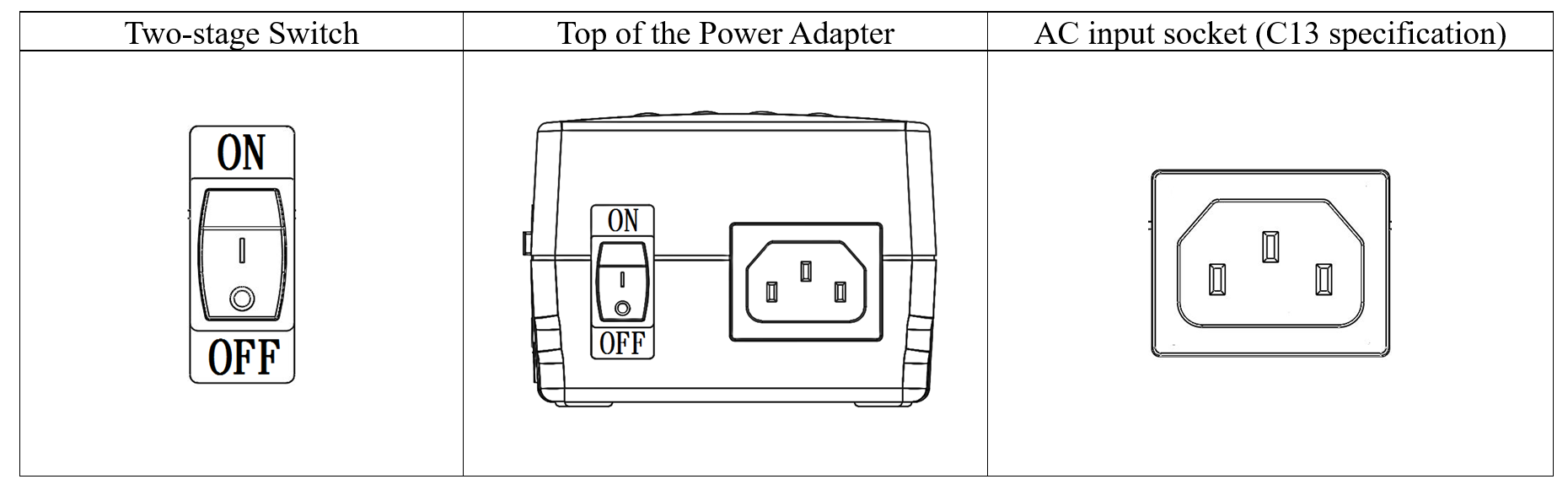
Connect one side of the cable to the AC power socket and the other side to the AC input socket (C13 specification).
Change the position of the two-stage switch on the power adapter to ON mode.
Change the position of the two-stage switch on the power adapter to OFF mode.
Disconnect the cable from the AC power socket and from the AC input socket (C13 specification).
Output Plug (DC)
The output plug provides power to the screwdriver.
The plug specifications are the following ones:
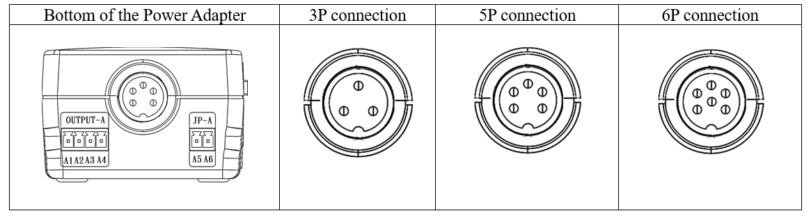
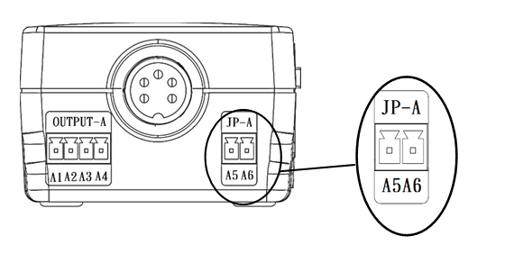
There are two terminals at the bottom of the power adapter:
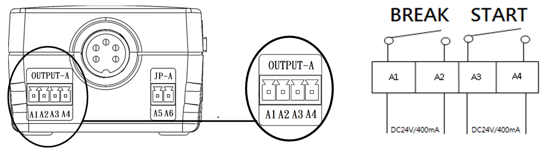
Output A: Output signal terminal:
Outputs A3 and A4: Switch on signal outputs. A3 and A4 will not export any voltage conduct signal when the tool is switched on.
Outputs A1 and A2: Switch off signal outputs. When the tool has reached its set torque and stopped, no voltage conduct signal will be exported.
No voltage conduct signal will be exported at a high voltage specification (DC 24 V/400 mA).
JP-A: External controller use terminal:
Outputs A5 and A6: Start signals for automation only.
For forward direction, use the external controller to check the conduction between the power adapter and the screwdriver.
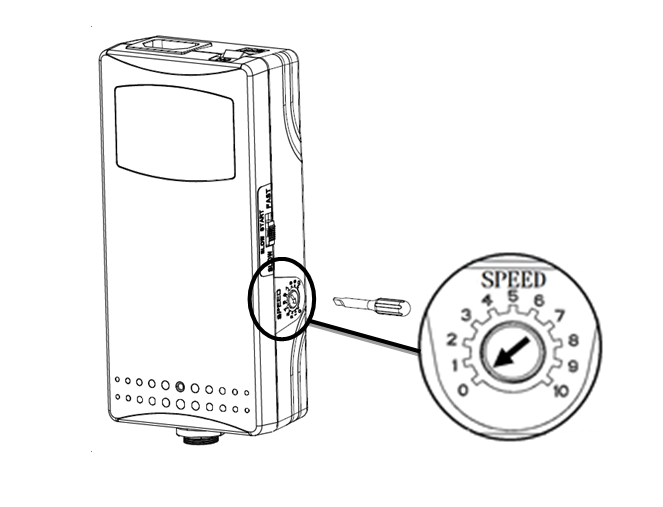
Speed Setting
To modify the speed, turn the speed setting screw on the side of the power adapter with a screwdriver:
To increase the speed, turn the speed setting screw clockwise (0 - 10) on the scale.
To decrease the speed, turn the speed setting screw counterclockwise (10 - 0) on the scale.
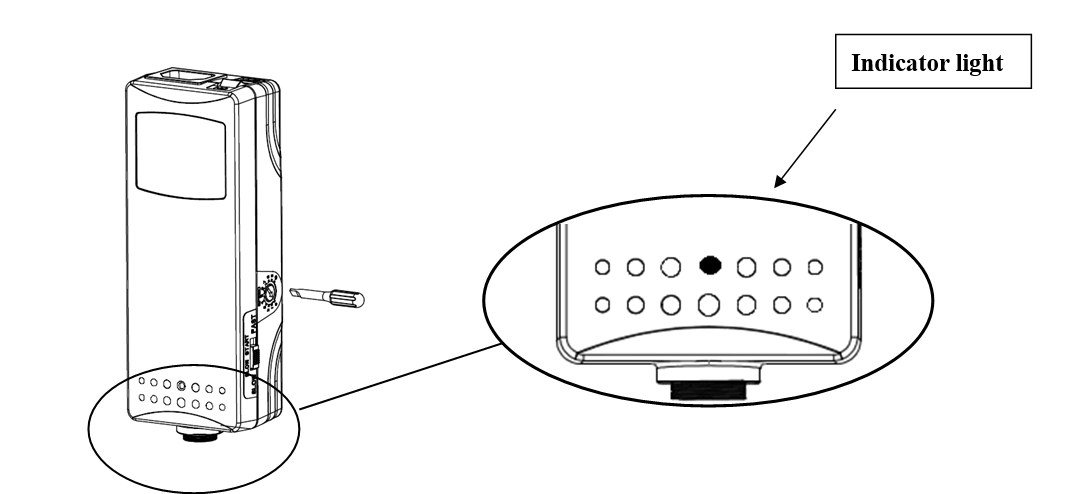
Indicator Light
The power adapter has an indicator light providing different kinds of information.
Green light | Activation (preceded by three orange flashes). |
Tightening OK. | |
No light | No DC voltage output. |
Flashing green light | Short circuit protection. |
Overpower protection. | |
Red light | Tightening NOT OK. |
Flashing red light | Heating protection (temperature set at 75-85 °C). |
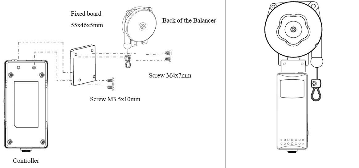
Assembly to a Balancer
There are screw holes at the bottom of the power adapter to assemble it to a balancer. See illustration below.