Square Drive Tool
Hydraulic Torque Wrench
製品情報
一般情報
捨てないでください - ユーザに渡してください
使用に関するステートメント
業務用専用です。
本製品とその付属品は絶対に改造しないでください。
損傷している場合は本製品を使用しないでください。
本製品のツールデータ、危険性の警告サインの読み取りができなくなったり、外れている場合、即座に交換してください。
The product must only be operated and serviced by trained and qualified personnel.
安全信号用語
安全信号用語の「危険」、「警告」、「注意」、「通知」には次のような意味があります:
危険 | 「危険」は、回避しなければ、死亡または重傷を負うことになる危険な状況を示します。 |
警告 | 「警告」は、回避しなければ、死亡または重傷を負う可能性のある危険な状況を示します。 |
注意 | 「注意」は安全警戒記号とともに用いられ、回避しなければ、軽傷または中程度の傷害を負う可能性のある危険な状況を示します。 |
通知 | 「通知」はケガに関係しない手順に対して用います。 |
保証
製品保証は、製品を最初に使用してから 12 か月で有効期限が切れますが、いかなる場合でも納品後、最長 13 か月で有効期限が切れます。
部品の通常の磨耗や傷は保証に含まれません。
通常の摩耗および裂傷は、その期間に典型的な標準的な工具のメンテナンス(時間、稼働時間などで表される)中に部品交換またはその他の調整/オーバーホールが必要なものです。
製品保証は、ツールとその構成部品の正しい使用、メンテナンスおよび修理に依存しています。
不適切なメンテナンス、または、保証期間中に Atlas Copco以外の人またはその認証サービスパートナーによって実施されたメンテナンスの結果発生した部品の損傷は保証対象となりません。
ツール部品の損傷や破壊を防ぐために、推奨されるメンテナンススケジュールに従ってツールの整備を行い、適切な手順に従ってください。
保証による修理は、必ず Atlas Copcoワークショップで、または認定サービスパートナーが実施してください。
その Atlas Copco契約により、延長保証と最新式の予防保守を提供します。ToolCover詳細については、お近くのサービス担当者にお問い合わせください。
電動モータの場合 :
電動モータが開かれていない場合のみ保証が適用されます。
ServAid
ServAidは以下のような技術情報を含むポータルで、継続的に更新されます:
規制及び安全に関する情報
技術データ
設置、運転およびサービスに関する注意事項
予備部品のリスト
アクセサリ
寸法図面
次をご覧ください:https://servaid.atlascopco.com.
詳細な技術情報については、最寄のAtlas Copco代理店までお問い合わせください。
安全データシート MSDS/SDS
安全性データシートは、Atlas Copcoが販売する化学製品について説明しています。
詳細についてはAtlas Copcoのウェブサイト www.atlascopco.com/sdsをご覧ください。
生産国
生産国については製品ラベルの情報をご参照ください。
寸法図面
寸法図は、寸法図アーカイブまたはServAidのいずれかにあります。
次をご覧ください:http://webbox.atlascopco.com/webbox/dimdrwあるいは https://servaid.atlascopco.com。
概要
技術製品データ
技術的な製品データは、ServAidまたはAtlas Copcoのウェブサイトにあります。
次をご覧ください:https://servaid.atlascopco.comあるいは www.atlascopco.com。
サービスの概要
サービスの推奨事項
予防メンテナンスを定期的に行うことをお勧めします。予防メンテナンスに関する詳細情報を参照してください。製品が正常に動作しない場合は、供用を停止して点検してください。
予防メンテナンスについての詳細な情報がない場合は、これらの一般的なガイドラインに従ってください。
適切な部品を正確に清掃します
不良部品や磨耗した部品を交換します
操作
人間工学に関するガイドライン
一般的な人間工学に基づいたガイドラインの本リストを読み、姿勢、コンポーネントの配置、作業環境において改善できるエリアを特定して、ご自身のワークステーションについてご検討ください。
頻繁に休憩をとり作業姿勢を変更すること。
ワークステーション領域を任意のニーズと作業タスクに適合させること。
静止荷重を避けるために部品やツールがどこに配置されるべきかを決定することにより、適度に手の届く範囲を調整すること。
テーブルや椅子などの作業タスクに適切なワークステーション設備を使用すること。
組立操作中に肩より高い位置または静止保存状態での作業を避けること。
肩より高い位置で作業する場合、トルクアーム、ホースリール、または重量バランサーなどを使用してツールの重量を減少させることにより静的筋の負荷を軽減すること。静的筋への負荷はツールを体に近づけて保持することによって軽減することもできます。また、負荷を身体の近くに保持することで静的筋肉への負荷を軽減することができます。
頻繁に休憩を取ること。
とりわけ、ある程度の力を要する作業において、腕または手首の無理のある姿勢を避けること。
必要とする目と頭の動きを最小限にするよう、視野を便利なように調整します。
作業タスクに適切な照明を使用すること。
作業タスクに適切なツールを選択すること。
騒音の多い環境では、防音保護具を使用してください。
過剰な振動レベルへの曝露を最小限にするには、高品質の挿入ツールおよび消耗品を使用してください。
操作手順
Electric Connections
Ensure proper power availability to prevent motor failure or dangerous electrical overloading. Use the recommended amperage listed on the motor nameplate. Do not use electric pump if ground is not connected on plug.
延長コードの長さを最小限にし、それらが適切なワイヤサイズで接地されていることを確認してください。
Extension cord should be #10 AWG gauge.
General Setup
All our hydraulic torque wrenches are supplied completely assembled, ready for use. An Atlas Copco hydraulic power pack, for use with your Atlas Copco hydraulic torque wrench, is recommended to provide the speed, pressure and portability that make your Atlas Copco System efficient and accurate.
The accuracy of your Atlas Copco hydraulic torque wrench is +/-3% based upon our manufacturer's specifications. This accuracy is certified through calibration tests conducted by Atlas Copco or any other qualified calibration facility whose program is traceable to the National Institute of Standards and Technology (N.I.S.T). We strongly suggest using Atlas Copco certified gauges (with a class 1 accuracy) to enhance the accuracy your torquing system.
エア接続
Ensure that you have sufficient air flow (58 up to 100 PSI / 4 up to 7 bar) to operate you pneumatic pump. If in doubt, compare the pump manufacturer's recommended air flow rating prior to pressurizing pump. Improper air flow may damage the pump motor.
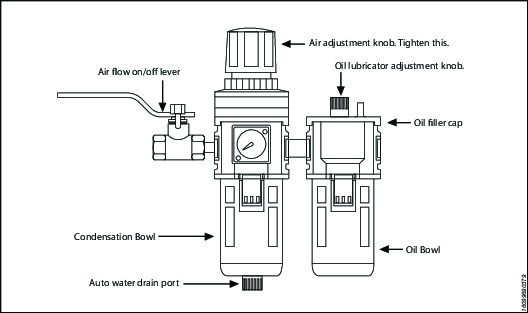
For best results use air hoses equal or larger than 3/4” internal diameter.
Use of a F.R.L. (Filter Regulator Lubricator) is highly recommended. Fill with oil and adjust the air admission with the adjustment knob.
Hydraulic Connections
Our hydraulic pumps are equipped with a zero-pressure relief valve. However, it could be possible that the retract side remain pressurized after the pump has been switched “off”. This trapped pressure prevents the user from loosening the retract-side fittings by hand. To release the pressure, simply push the black button on top of the solenoid. All fittings are free to be manually tightened.
Never disconnect or connect any hydraulic hoses or fittings without first unloading the wrench and the pump. If the system includes a gauge, double check the gauge to assure pressure has been released. When making connections with quick disconnect couplings, make sure the couplings are fully engaged. 継手やゲージなどのネジ接続部は、クリーンでしっかり締められており、漏れがない状態でなければなりません。
作動圧力
The tool's maximum working pressure is 10,000 psi (700 bar). Make sure that all hydraulic equipment (pumps, hoses, couplers) used with this tool are rated for 10,000 psi (700 bar) working pressure. Review the documentation for the hydraulic pump in use to ensure pressure does not exceed 10,000 psi.
Connecting the System
The Atlas Copco hydraulic torque wrench and the power pack are connected by a 10,000 psi (700 bar) operating pressure twinline hose assembly. The safety ratio of the Atlas Copco hydraulic hose is 4/1. On each twin hydraulic hose, one line must be MALE-MALE and the other line must be FEMALE-FEMALE in order to assure a correct interaction between pump and machine. Connect the twinline hose to the swivel as shown:
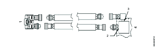
参考 | 説明 |
|---|---|
1 | レンチ |
2 | ポートA |
3 | Port 'R' |
4 | ポンプ |
Check all coupler connections because, after the system has been pressurized, you will not be able to tighten the couplers by hand and using tools will damage the couplers.
Check all coupler connected properly with no gaps between collar and fittings. Never use spanners and other tools to tighten or loose couplers.
Ensure connectors are fully engaged and screwed snugly together.
Never use two twin hydraulic hoses between pump and machine. If so, you have the high pressure on the retract side and your machine will not work properly. To avoid tool malfunction, do not reverse connectors. Do not try to loosen the swivel assembly at any moment.
Operating Hydraulic Pump
Setting Working Pressure on the Pump
To set the pressure on the pump, follow this procedure:
Loosen the knurled locking ring below the "T" handle on the pump's external pressure regulator. Then turn the "T" handle counter clockwise (CCW) until it turns freely and easily.
Turn the pump "on". Using the pump's remote control pendant, push down the advance switch (or button on air pumps) and hold it.
While holding the pump in the advance mode, slowly turn the "T" handle clockwise and observe the pump pressure gauge rise.

Always adjust the regulator in order to increase the pressure up - Never down. アプリケーション上のツールを使って油圧レギュレータを調整しないでください。
When your gauge reaches 4,000 psi stop turning the "T" handle and let the gauge settle out.
If the pressure continues to rise (above 4,000 psi), release the advance button and back off your pressure slightly-by turning CCW on the "T" handle. Then re-depress the advance switch on you remote and slowly bring pressure up to 4,000 psi again.
When the pressure is correct, turn the pump "off" and tighten the knurled lock nut provided under the "T" handle. This sets pump pressure, which determines torque tool output.
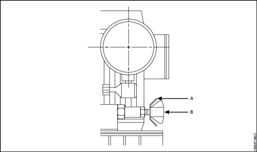
参考
説明
A
ロッキングリング
B
T - Handle
Once your target pressure is set and locked, cycle the pump once more to ensure that your pressure setting did not change as you turned down the knurled knob.
Applying Torque to Wrench
Having set your target pressure, cycle the tool three or four times to full pressure. Cycling the tool ensures that the system is operating properly and removes trapped air, if any.
Verify that any impact sockets used are rated to accept the full torque output of the tool they are to be used with. Ensure the correct size impact socket for the nut A/F has been selected, placed on the square drive and secure with a locking pin and ring.
Place the tool and the socket on the nut, making sure that the socket has fully engaged the nut, check that the drive retainer is engaged.
反動アームが静止している物体(隣接するナット、フランジ、機器筐体など)にしっかりと接合していることを確認してください。 When positioning the wrench, make sure that the hose connections are well clear of any obstructions and that all body parts are safely out of harm's way. その後に(その前ではなく)、適切なツールの配置を確認するために、システムに瞬間的な圧力を加えてください。 If it doesn't look or act right, stop and re-adjust the reaction arm.
Read Safety Instructions supplied with the torque wrench for further guidance on tool usage.
By pushing down on the remote control button in the advance position, the rear of the tool will be pushed back until its reaction arm will contact its reaction point.
Continue to hold down the button as the socket turns until you hear an audible "click" which will signify the hydraulic cylinder inside the tool is fully extended and will not turn the advance further.

Continuing to hold down the remote control button will result in a rapid build up of pressure to the point of where the gauge reads what was preset prior to applying the wrench.
The reading of full preset pressure after the cylinder is extended DOES NOT INDICATE that this pressure (torque) is applied to the bolt. It only indicates that the cylinder is fully extended and cannot turn the socket or the ratchet link further until the tool automatically resets itself.
Releasing the remote control button will retract the cylinder. The tool will automatically reset itself and the operator will hear an audible "click" indicating he can again push the remote control button and the socket will turn. Each time the cylinder is extended and retracted, it is called a cycle. Successive cycles are made until the tool "stalls" at the pre-set Torque/psi with an accuracy of +/-3%. Repeatability is +/- 1%.
Always attempt one final cycle to ensure the "stall" point has been reached.
Should the tool "lock-on" after the final cycle, push down on the remote control button once more (to build pressure) and, while maintaining this pressure, pull back on the external disengagement lever (RT) or reaction Pawl (RTX). Releasing the remote control while continuing to hold back on the pawl lever/reaction pawl will allow the tool to be removed easily.
Loosening Procedures
First, set the pump to 9,000 psi (Do not try directly at 10.000 psi). Change the drive and the reaction arm to the loosening mode (Left = Loose), assuring the reaction arm abuts squarely off a solid reaction point. Press and hold the remote control button down. Pressure will decrease as the socket begins to turn. As the cylinder extends fully, you will hear an audible "click". Release the remote control button, and the cylinder automatically retracts, at this time you will again hear the audible "click". Repeat this process until the fastener can be removed by hand.
If the bolt does not loosen with the above procedure, it is an indication that you need a larger tool to loosen the bolt.
Setting Torque
All Atlas Copco power packs operate at a pressure range from 500 to 10,000 psi and are fully adjustable. They have been engineered and designed for portability and high flow for increased speed. Before using your Atlas Copco power pack, check the following points.
Is the reservoir filled with oil?
Where is the closest electrical outlet at the job site?
Is there enough air pressure (60 to 100 psi) and Air flow at the job site? (Air units only)
Is the gauge mounted and rated for 10,000 psi / 700 bar?
作動圧力
The pump's maximum working pressure is 10,000 psi / 700 bar. Make sure all hydraulic equipment and accessories are rated for 10,000 psi / 700 bar operating pressure. Hydraulic pumps are available with higher pressure outputs, if not using an Atlas Copco power pack verify maximum operating pressure of the unit being used and ensure the system maximum operating pressure (10,000 psi / 700 bar) is not exceeded.
Hydraulic Connections
Never disconnect or connect hydraulic hoses or fittings without first unloading the wrench. Unplug the electrical cord of the pump, and open all hydraulic controls several times to assure that the system has been depressurized. If the system includes a gauge, double check the gauge to assure pressure has been released. When making a connection with quick disconnect couplings, make sure the couplings are fully engaged threaded connections such a fittings, gauges etc. must be clean and securely tightened and leak free.
Loose or improperly threaded couplers can be potentially dangerous if pressurized, however, severe over tightening can cause premature thread failure. 継手はしっかりと締め付けて、漏れないようにする必要があります。つかんだり、触れたり、またはいかなる方法でも油圧漏れに接触しないでください。漏れた油が皮膚に染みこんで、怪我をすることがあります。 Do not subject the hose and potential hazard such as sharp surfaces, extreme heat or heavy impact. Do not allow the hose to kink and twist. Inspect the hose for wear before it is used.
Electrical Power
Check the proper electrical supply before connecting.
This motor may spark. Do not operate in an explosive atmosphere or in pressure of conductive liquids.
Do not use a power or extension cord that is damaged or has exposed wiring.
All single phase motors come equipped with a three prong grounding type plus to fit the proper grounded type electrical outlet. Do not use a two prong ungrounded extension cord as the pump's motor must be grounded.
Compare motor nameplate against power availability to prevent motor burnout or dangerous electrical overloading.
Prior to Use
Check hydraulic oil (Use Atlas Copco maximiser range Grade 46) level to prevent possible pump burnout. Open the filler plug located on the reservoir plate. Look at oil fill level on the oil sight gauge. The oil level should be approximately 2" from the top of the reservoir plate- with motor off. Add oil as necessary. Do not mix different grades of oil. Make sure all desired gauge, valve, hose and quick coupler connections are tight and secure before operating. The use of a pressure gauge is required for normal pump operation. Mounted on the manifold, the gauge permits the operator to monitor the load on the wrench. Class1 certified calibrated gauges are available for most applications.
Operating Square Drive
Changing Drive Direction
To remove the square drive, push the round button on the drive retainer and gently pull on the square end of the square drive (for RT20, 25 & 50, push on the drive retainer while turning it counter-clockwise). To insert the drive in the tool, place the drive in the desired direction, engage drive and bushing splines, then twist drive and bushing until ratchet Spline can be engaged. Push drive through ratchet.
Push drive retainer button, engage retainer with drive and release button to lock the square drive in position.
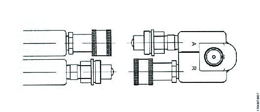
Reaction Arm
All Atlas Copco hydraulic torque wrenches are equipped with a universal reaction arm. These reaction arms will absorb and counteract forces created as the unit operates. The reaction arm should extend in the same direction of the square drive; however, slight adjustments may be made to suit your particular application. The RT reaction arm is made of special aircraft alloy and is 360° adjustable.
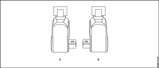
参考 | 説明 |
|---|---|
A | Right = Tight |
B | Left = Loose |
The standard RT reaction arm cannot be welded on and should not be modified.
The reaction arm for all RT Monobloc Housing is splined to slide over the rear (cylinder) portion of the tool. In operation, the reaction arm must be fully engaged and secured by inserting the spring loaded reaction arm lever at the base of the housing (end cap). 操作の前に反動アームが完全にかみ合っていることを確認してください。
Setting Torque
Once the system is fully connected and proper power supply available, the operator may now adjust the pump pressure to the level needed for the application.
When tightening, use the manufacturer's specifications to determine the torque value which you will ultimately require.
Torque sequence may vary from plant to plant and even within individual plants, depending upon the gasket material, etc. Always follow local procedures.
Refer to the pressure-torque conversion table applicable to the tool which you intend to use, Torque chats are available on ServAId .
Square/Allen Drive Working Torque
ドライブサイズ The square or hex drive of each drive is limited in its maximum output by its material and its engagement area. Since Atlas Copco uses a specially suited alloy-steel for its drive members, the following maximum torque output can be achieved without drive failure, provided the reaction member abuts close to the same plane as the nut to be turned.
If the reaction arm cannot abut on the same plane as the nut to be turned, less torque should be applied, as the additional side load has to be taken into consideration. When toque requirements are close in excess of the values listed above, use RT's/-9/ Sockets Hex-Drive with replaceable Hex Insert Bits.
RT series is available with square drive (standard) or option hexagonal/Allen drive. The table below reviews ideal working range for the respective drives.
ドライブサイズ Inch or mm | ドライブタイプ | 最大作動圧力 | Probable Failure | ||
フィート・ポンド | Nm | フィート・ポンド | Nm | ||
1/2" | HEX: | 353 | 478 | 392 | 531 |
1/2" | 角 | 367 | 497 | 408 | 553 |
5/8" | HEX: | 689 | 934 | 766 | 1038 |
3/4" | HEX: | 1191 | 1614 | 1324 | 1794 |
3/4" | 角 | 1239 | 1679 | 1377 | 1865 |
7/8" | HEX: | 1892 | 2565 | 2102 | 2848 |
1" | HEX: | 2824 | 3827 | 3138 | 4252 |
1" | 角 | 2937 | 3980 | 3263 | 4422 |
1 - 1/8" | HEX: | 4021 | 5448 | 4468 | 6054 |
1 - 1/4" | HEX: | 5516 | 7474 | 6129 | 8304 |
1 - 3/8" | HEX: | 7341 | 9948 | 8157 | 11053 |
1 - 1/2" | HEX: | 9531 | 12915 | 10590 | 14350 |
1 - 1/2" | 角 | 9912 | 13432 | 11014 | 14924 |
1 - 5/8" | HEX: | 12118 | 16420 | 13465 | 18245 |
1 - 3/4" | HEX: | 15135 | 20508 | 16817 | 22787 |
1 - 7/8" | HEX: | 18616 | 25224 | 20684 | 28027 |
2" | HEX: | 22593 | 30613 | 25103 | 34015 |
2 - 1/4" | HEX: | 32168 | 43588 | 35742 | 48431 |
2 - 1/2" | HEX: | 44126 | 59791 | 49029 | 66435 |
2 - 1/2" | 角 | 45891 | 62183 | 50990 | 69092 |
12mm | HEX: | 298 | 404 | 331 | 449 |
17mm | HEX: | 847 | 1147 | 941 | 1275 |
19mm | HEX: | 1182 | 1602 | 1313 | 1780 |
22mm | HEX: | 1835 | 2486 | 2039 | 2763 |
24mm | HEX: | 2382 | 3228 | 2647 | 3587 |
27mm | HEX: | 3392 | 4596 | 3769 | 5107 |
32mm | HEX: | 5647 | 7652 | 6275 | 8502 |
36mm | HEX: | 8040 | 10895 | 8934 | 12105 |
41mm | HEX: | 11878 | 16094 | 13197 | 17882 |
46mm | HEX: | 16774 | 22730 | 18638 | 25255 |
50mm | HEX: | 21542 | 29190 | 23935 | 32433 |
サービス
メンテナンスに関する注意事項
サービスとメンテナンスに関する推奨事項
ツールの操作、修理、保守の際、あるいはツールのアクセサリを交換する際、または、その近くにいる場合、必ず目と顔を守る耐衝撃性防具を着用してください。
調査、保守、修理作業はすべて、システム全体の圧力がゼロの場合にのみ実行してください。
最適な性能を得るために、ツール、パワーパック、ホース、コネクタ、電線ケーブルやアクセサリに視覚的な損傷がないか頻繁に検査してください。ツールおよびポンプのメンテナンスに関する指示に、常に従ってください。
サービス間隔に関するガイダンス
訓練を受けた人員が適切なメンテナンススケジュールを守った場合、油圧レンチは長年にわたって問題なく使用できます。ただし、ツールはすべて、長期間使用すると摩耗します。ツールの寿命に影響する要因:
高サイクル速度
高負荷使用
衝撃
汚れた、高温または湿気の多い環境での動作
さまざまな反力方法
メンテナンス不良
レンチが正常に作動するように、定期的に注油とオーバーホールを行うことをお勧めします。高トルクや高サイクル速度、長時間の締め付けを行う場合には、より頻繁にサービス間隔が必要になることがあります。レンチが正しく作動しない場合には、ただちに点検に出してください。
以下のサービス間隔はあくまでも目安です。ユースケースやアプリケーションはそれぞれ異なるため、作業環境や使用度に合わせて適切な計画メンテナンスを実施するのはエンドユーザーの責任となります。ツールの使用記録を保管してください。この記録は、ツールやコンポーネントのサービス、校正、交換の計画に役立ちます。
ライトデューティー
例:低圧でのまれな定格荷重の 40% 未満での使用。
潤滑:6 か月毎
オーバーホール:12ヶ月毎
ノーマルデューティ
例:定期的な、定格荷重の 80% 未満での使用。
潤滑:3 か月毎
オーバーホール:ドライブピンの交換を含め、12 か月毎。セクション 潤滑 を参照してください。
ヘビーデューティー
例:継続的なあらゆる圧力で、定格荷重の 80% 超での使用。腐食したボルトを緩めるのに定期的に使用。
潤滑:1 か月毎
オーバーホール:ドライブピンとドライブの爪交換を含め、6 か月毎。セクション 潤滑 を参照してください。
ツール交換
製品所有者は、ツール交換ポリシーに基づいたサービス計画を策定・実行する必要があります。このポリシーにより、ツールが使用できなくなる前に稼働しているツールが交換されることが保証されます。多様な動作環境が想定され、ツールの保守メンテナンスが一様でない可能性があるため、ツールの寿命を定義することは困難です。
傷跡、へこみ、材料の欠損などの視覚的な摩耗の兆候が見られる場合は、ツールがもはや有用ではないことを示します。摩耗の兆候が見られるツールは、保守サービスしてください。ツールの状態を維持するために、損傷した部品をすべて交換してください。もしツールに圧力保持部品や反力アームへの大きな損傷が見られる場合、安全上の理由からそのツールを直ちに取り除くのが正しい処置です。
詳細については、「サービス間隔に関するガイダンス」を参照してください。
予防メンテナンス
油圧トルクレンチシステムを良好な状態に保つために、使用期間ごとに次のメンテナンス手順を実行してください。
外側の表面をすべて拭き取り、ツールに損傷の兆候がないか目視検査します。必要に応じて調査します。
すべての油圧継手と接続部に油圧漏れの兆候がないか調べます。必要に応じて調査します。
すべての油圧カップリングが清潔で、破片がないことを確認してください。
ホースの全長にわたって検査します。切り傷や擦り傷がないか調べます。スエージ加工された端に細心の注意を払い、漏れの兆候がないか探します。
機器が正常に機能している場合は、Shell Ensis や Castrol Rustillo などの適切な防錆油をスプレーし、次回の使用に備えて保管します。
オーバーホールの手順
レンチをポンプに接続します。
すべてのメカニズムが期待どおりに機能することを確認する圧力テストを実施します。
誤動作や油圧漏れがないか調べます。
システムを減圧し、すべてのカップリングを外します。
レンチを分解します。
すべてのシールとスプリングを交換します。
ドライブピンを交換します。
損傷や摩耗の兆候が見られるその他のコンポーネントをすべて交換します。
レンチを再潤滑して再び組み立て直します。
圧力テストを実施して、すべてのメカニズムが期待どおりに機能することを確認します。
レンチを校正して、トルク出力が期待どおりであることを確認します。
潤滑手順
潤滑油ガイド
ドライブコンポーネント | Molykote 1000 |
シール | Rocol Sapphire Aqua-Sil |
ファスナー | Loctite 243 |
テーパー油圧ねじ | Loctite 577 |
潤滑
レンチを良好な状態に保つには、サービス間隔の合間にドライブコンポーネントに定期的に注油してください。
潤滑前の分解:
角ドライブを取り外します。
アクセスプラグ [×2] を取り外します。
シュラウドねじ [×2] とシュラウドを取り外します。
固定クリップ [×2] を取り外します。
ドライブスリーブ [×2] を取り外します。
ドライブピンをアクセスプラグの穴に合わせます。ピンをハウジングから押し出してドライブアセンブリを取り外します。
ハウジングからドライブアセンブリを取り外します。
潤滑メンテナンス中は、次を行います:
ドライブピンに摩耗や損傷の兆候がないか調べます。必要に応じてピンを交換してください。
ラチェットの歯先に損傷の兆候がないか調べます。必要に応じてラチェットを交換してください。
ドライブの爪の歯に損傷の兆候がないか調べます。必要に応じてドライブの爪を交換してください。
ドライブの爪のスプリングに破損の兆候がないか調べます。必要に応じてスプリングを交換してください。
網掛け部分に潤滑剤 Molykote 1000 を塗ります。
組み立ての手順は分解の手順と同じですが、逆になります。
トラブルシューティング
Troubleshooting of Hydraulic Torque Wrench
Tool failure, although rare, does occur. Such failure is most often in the hydraulic couplers or hoses. These items are repairable or replaceable immediately, since they are available universally. Failures of structural members of the tool are quite rare, however, replacement parts are available from stock. All repairs to Atlas Copco tools may be made by reasonably experienced individuals according to the aforementioned instructions. Otherwise, please contact Atlas Copco to schedule a quick repair of the tool.
Recommended Service intervals are :
Heavy duty use or use in corrosive/harsh environments – every 3 months internal drive components may require frequent inspection and re-lubrication under heavy duty cycles, e.g. weekly.
Normal use – every 6 months.
Light or infrequent use – every 12 months.
Troubleshooting Powerpacks
Atlas Copco Hydraulic Power Packs are precision-built units and, as such, do require a certain amount of care and maintenance
Hydraulic Oil should be completely changed after every 300 hours of operation, or at least twice a year. Always make sure the reservoir is filled with fluid. Always use Atlas Copco Maximizer range of oils for best performance.
Couplers and fittings should be checked periodically for leaks. Dirt or foreign materials should be kept away from fittings. Clean before use.
Hydraulic Gauge: Some gauges are liquid filled. Should this liquid level drop, it indicates external leakage, and replacement is necessary. Should the gauge fill with hydraulic oil, it indicates internal failure and it should be discarded.
Filter on Pump: The filter should be replaced twice a year in normal use and more often if the pump is used daily or in a dirty, harsh environment.
リモート コントロール (Air Unit) The airline to the remote control unit should be checked for obstructions or kinks in the line periodically. If there is a bend or break in the line, it must be replaced. The spring- loaded buttons on the remote handle should be checked in the event of operating difficulties. (Electric Unit) The switch buttons should be checked periodically if any indications of problems exist.
Air Valve: This valve should be checked twice a year.
Armature: (Electric Unit) Check yearly.
Pumping unit: The pump should be overhauled every 2 years. This can be done by Atlas Copco or by a qualified hydraulic service centre.
Troubleshooting Routines
Test 1
Attach hoses to pump and tool in the normal manner.
Press the advance button and hold it down.
If the pump pressure builds and the hoses "flex" but the tool still refuses to cycle, the problem is most likely a loose or defective coupling connection. To find out where the bad coupling is, remove the tool from the hoses and marry the loose ends together and cycle the pump. If the gauge pressure reads no more than 500 PSI, then the bad fitting is on the tool. A significantly greater pressure indicates that the problem is in either the pump or a hose fitting.
Test 2
Remove screws from pump motor to reservoir, slide pump motor to the back while keeping pistons into oil.
Turn pump on. If you have no oil coming out from the solenoid tube, change the solenoid.
Tight the regulating valve to maximum, Push on the advance button and while holding down, look if any oil is coming out from the regulating tube. If oil is coming out, change the regulating valve.
Test 3
Remove tool from hoses.
Cycle pump.
If pump fails to build pressure, the problem is with the pump. If it does build pressure, the problem is with hydraulic blow-by in the tool.
Test 4
This test should be run prior to every use of an Atlas Copco Tool
Connect the tool, pump and hoses together as normal.
Cycle the pump several times.
Cycle the system once more and observe the sequence of operation.
As you depress the advance button, the tool drive shroud turn about 24 degrees and you should hear an audible "click". You will also notice that the disengagement levers will move to the rear of the tool and spring forward.
At this point, release the advance button. You should see no further movement and after a moment you will hear another audible "click". This is how the tools are designed to operate.
If you observe any other sequence of operation, the system is out of order and cannot deliver more than 10% of its designed capacity.
Take immediate corrective action. For reference, tools and pumps are designed from the factory plumbed as follows. This ensures that the tool, pump and ONE hose cannot possible be connected up incorrectly.
Test 5
Tool | ホース | ポンプ |
|---|---|---|
Advanced Side-Male | Advance side- Female to Female | Advance side-Male |
Retract side-Female | Retract Side-Male to Male | Retract Side-Female |
Note that connecting two (or any even numbers) of hoses together creates "one" hose which is plumbed backwards! Male to Female and Female to Male. This will cause the system to operate backwards per Test #5 above. If you hose isn’t long enough, connect 3 hoses together, move your pump or call Atlas Copco for a longer hose assembly.
トラブルシューティング、問題と必要な処置
徴候 | Probable Cause | Required Action |
|---|---|---|
Gauge shows pressure build-up but the tool will not cycle | Couplings are loose or not working. Solenoid is not working | Tighten and/or replace couplings. Use Test #1 to isolate problem Use test #2. if not working replace solenoid |
Cylinder will not retract | 1.See above. | 1. See above. |
2.Voltage to electric pump is too low to line drop or inadequate amperage is available. | 2. Get shorter extension cord or upgrade to 12AWG, 25 amp rating or better. | |
3.Linkage between piston rod and drive pawl are broken. | 3.必要に応じてシリンダーを交換してください。 | |
Cylinder pressure will not build | 1. Oil blow by in tool (Piston seal leak, blown O-ring, cracked piston) | 1.機械部品の交換アトラスコプコの代理店までご連絡ください。 |
2. Pump Problem. | 2. Remove screws from pump motor to reservoir, slide pump motor to the back while keeping pistons into oil. Turn pump on. If you have no oil coming out from the solenoid tube, change the solenoid. 2A If pump sounds like a lot of pebbles in a tin can, the problem may be a worn motor coupling-remove motor from base plate-using a pair of needle nose pliers removes the motor coupling-if worn replace. アトラスコプコの代理店までご連絡ください。 2B If pump sounds like a lot of pebbles in a tin can, the problem may be a worn motor coupling-remove motor from base plate-using a pair of needle nose pliers removes the motor coupling-if worn replace. アトラスコプコの代理店までご連絡ください。 2C。 Air pump- Fault FRL due to excessive moisture and/or dirt in air supply. Disassemble and change. アトラスコプコの代理店までご連絡ください。 2D。 Air pumps- Replace faulty remote control valve cartridge. | |
Cylinder/tool leaks | 1. Safety relief valve on swivel has lifted. | 1A Tighten all hose and couplers. If leak continues, adjust safety setting – Test #4. 1B Check to see if the system is properly plumbed by running test #5 (high pressure on retract side will lift the safety relief valve). |
2. Blown O-ring in cylinder. | 2. Replace O-Ring with proper high pressure O-Ring. アトラスコプコの代理店までご連絡ください。 | |
3.Defective gland seal. | 3. Replace gland seal. アトラスコプコの代理店までご連絡ください。 | |
Tool operates backwards | 1. Couplings reversed. | 1. Run test #5. Replumb system as necessary. |
2. Multiple hoses in even numbers. | 2. As plumbed, Atlas Copco hoses may only be joined together in odd numbers ONLY if it is necessary to use 2, 4, 6 hoses-make an adapter from spare high pressure couplings and nipples. | |
Ratchet returns with retract stroke | Broken or otherwise inoperable reaction pawl. | |
Ratchet will not take successive strokes. | 1. Broken or otherwise inoperative drive pawl or spring. | 1. Replace drive pawl and/or spring. アトラスコプコの代理店までご連絡ください。 |
2. Cylinder not retracting completely. Ratchet will not take successive strokes. | 2.Remove tool from nut and cycle freely for several strokes. If problem persists, check pawls. 2A Operator not allowing adequate time for cylinder to retract fully | |
3. Linkage between piston rod and drive plates is broken. | 3. Replace parts as necessary -Contact Atlas Copco service. | |
Tool locks onto nut. | 1. Reaction pawl is loaded when the tool is maxed out in torque. | 1. Press advance button on remote and build pressure- continue to press down on remote while pulling back on one of the disengagement levers- release remote while continuing to hold back on levers. |
2. Tool is operating backwards. | 2. Push advance button down-tool should immediately fall free- Run test #5. | |
3.Tool is wedged under a fixed object. | 3. Remove shroud from around ratchet. Using any tool available, pry the drive pawl out of the ratchet and at the same time pull back on the disengagement levers. Tool should swing free or turn away the socket or obstruction. | |
Gauge records no pressure | 1. Gauge connection is loose. | 1. Tighten coupling. |
2. Bad gauge. | 2. Replace gauge. | |
3. Pump will not build pressure. | 3. See cylinder will not build pressure above. See cylinder will not build pressure above. | |
4. Tools seals are blown. | 4. Replace defective seals. アトラスコプコの代理店までご連絡ください。 |
トラブルシューティング、問題と必要な処置
徴候 | Probable Cause | Required Action |
|---|---|---|
Pump will not build pressure. | 1. Air Electric supply is low. | 1.エア圧力レギュレータを確認します |
2. Defective relief or regulator valve. | 2. Replace valve. アトラスコプコの代理店までご連絡ください。 | |
3. Low oil or clogged filter. | 3. Fill reservoir and clean filter. | |
4. Internal leak in oil line from external relief valve to pump body. | 4. Open reservoir, inspect oil line while trying to build pressure- if leaking tighten fittings or replace. | |
5. Defective Solenoid or regulating valve. | 5. See “Cylinder will not build pressure-#2 above” | |
Motor sluggish and inefficient “sounds sick” slow to build pressure. | 1. Air or electric supply is low. | 1. See #1 in preceding block |
2. Clogged filter. | 2.フィルターを清掃または交換します | |
Pump heats up. | 1. Improper use. | 1. Operator is continuing to hold down on the advance stroke after the cylinder has reached end of stroke- this causes a lot of oil to go through a very small hole in relief-valve- causing heat build-up. Have operator release advance stroke after disengagement levers spring forward. |
2. Remote control is left in “on” position when pump is not actively in use. | 2. Turn pump off whenever not actually being used. DO NOT leave pump running when tool is not in use. | |
Pump cannot reach 10,000 psi, only 9,000psi | Change regulating valve | 1A.Remove 3 screws of 4 port block manifold IB. Remove regulating valve IC: Replace new regulating valve ID Don’t forget metal ring IE. Check o’rings on block manifold IF. Replace block manifold IG. Place 1 drop of loctite on each screw IH. Tighten screws firmly - double check screws are fully tightened. |
Pressure can’t reach 4,000 psi | Change cut off valve(s) | IA. Remove the pump from tank IB. Change cut-off valves 3,250 psi /70 bar 90% Chance pump is workingIB. Change cut-off valves 3,250 psi /70 bar 90% Chance pump is working IC: If pump can’t get 10,000 psi change cut-off valve 1,250 psi/350 bar |
Pressure not stable (big variation) | Change solenoid (115v), (220v) | IA. Remove top solenoid IB. Replace new top solenoid IC:Oリングが損傷しています |
Pressure not stable (small variation) | Change check valves Part# 20374 Need special tooling | IA. Remove the pump from tank IB. Replace check valve IC: Do not tight too much |
No pressure | Check piping | IA. Remove the pump from tank or Check piping couplers IB. Check t-coupler inside the pump |
Uncontrolled pressure | 1. Check coupling Part#10190 | IA. Remove the pump from the tank IB. Remove piping IC: Remove block pump (screws# 20444) ID Check attentively coupling IE. Do not forget to replace keys(part #10184) |
2. Check pumps Part# 10168-10169-10170 | 2A Remove the pump from the tank 2B Untighten pump’s screws 2C。 Check seals 2D。交換 2E。 Tighten firmly |
トラブルシューティング、問題と必要な処置
徴候 | Probable Cause | Required Action |
|---|---|---|
Motor doesn’t run | 1.Check fuse 16 a Part# 10064 | 1. Change fuse 16 a (white - on top) |
2. Check electrical box | 2. Check for disconnection | |
3. Check 115v cord | 3.Check for wire cut or disconnect | |
4. Check plug | 4. Check for wire disconnect | |
5.Check remote control | 5. Check for wire disconnect | |
Motor start difficult | 1. Bearing Part#10198 & 10178 | IA. Remove the pump from the tank IB. Remove block pump IC: Disassemble block pump ID Change bearing |
2. Remote control handswitch small white plastic support | 2A Open the hand switch 2B. Replace small plastic parts | |
Blown fuses when starting | Check if fuse 16 a is blown Part# 10064 | To avoid the problem don’t run motor If hydraulic hose are not connected |
Hose or tool fitting is damaged or leaks. | 1. Broken or melted plastic outer covering. | 1. If underlying plastic is still intact continue operation. Inspect frequently.If underlying plastic is still intact continue operation. Inspect frequently. |
2. Frayed plastic strands. | 2. Cut hose in half and discard. Replace hose. | |
3. Oil leaks through fibres. | 3. Cut hose in half and discard. Replace hose. | |
4. Broken fittings. | 4. Remove old fitting and replace with STEEL high pressure fittings only. After changing fittings, always run test #5 to insure proper plumbing. | |
Electric pump will not run | 1. Loose electric connections in control box. | 1. Open control box and visually inspect for loose threaded or push-on connectors. |
2. Motor burned up. | 2. Replace motor components whichever is necessary. アトラスコプコの代理店までご連絡ください。 | |
ヒューズ | 3.ヒューズを交換します。 |