Wind Turbine Bolt Tensioners
Product Information
General Information
Safety Signal Words
The safety signal words Danger, Warning, Caution, and Notice have the following meanings:
DANGER | DANGER indicates a hazardous situation which, if not avoided, will result in death or serious injury. |
WARNING | WARNING indicates a hazardous situation which, if not avoided, could result in death or serious injury. |
CAUTION | CAUTION, used with the safety alert symbol, indicates a hazardous situation which, if not avoided, could result in minor or moderate injury. |
NOTICE | NOTICE is used to address practices not related to personal injury. |
Warranty
Product warranty will expire 12+1 months after dispatch from Atlas Copco's Distribution Center.
Normal wear and tear on parts is not included within the warranty.
Normal wear and tear is that which requires a part change or other adjustment/overhaul during standard tools maintenance typical for that period (expressed in time, operation hours or otherwise).
Puller bars have its fatigue life and warrantied for 5000 cycles.
The product warranty relies on the correct use, maintenance, and repair of the tool and its component parts.
Damage to parts that occurs as a result of inadequate maintenance or performed by parties other than Atlas Copco or their Certified Service Partners during the warranty period is not covered by the warranty.
To avoid damage or destruction of tool parts, service the tool according to the recommended maintenance schedules and follow the correct instructions.
Warranty repairs are only performed in Atlas Copco workshops or by Certified Service Partners.
Atlas Copco offers extended warranty and state of the art preventive maintenance through its ToolCover contracts. For further information contact your local Service representative.
Website
Information concerning our Products, Accessories, Spare Parts and Published Matters can be found on the Atlas Copco website.
Please visit: www.atlascopco.com.
ServAid
ServAid is a portal that is continuously updated and contains Technical Information, such as:
Regulatory and Safety Information
Technical Data
Installation, Operation and Service Instructions
Spare Parts Lists
Accessories
Dimensional Drawings
Please visit: https://servaid.atlascopco.com.
For further Technical Information, please contact your local Atlas Copco representative.
Safety Data Sheets MSDS/SDS
The Safety Data Sheets describe the chemical products sold by Atlas Copco.
Please consult the Atlas Copco website for more information www.atlascopco.com/sds.
Country of Origin
For the Country of Origin, please refer to the information on the product label.
Dimensional Drawings
Dimensional Drawings can be found either in the Dimensional Drawings Archive, or on ServAid.
Please visit: http://webbox.atlascopco.com/webbox/dimdrw or https://servaid.atlascopco.com.
Overview
Product Overview
WTB products are available with below features:
Grip Surface:
For easy user handling.
Optional Cycle Counter
For maintenance scheduling purposes all Aero WTB Tools offer an optional mechanical pressure cycle counter.
Swivel Connection:
360º swivel operation allows the hydraulic hoses to be positioned in the best possible position to allow open access to the tensioning tools.
Geared Nut Run Down:
The inclusion of a gear nut rundown mechanism offers a very rapid and consistent way of seating the hexagon nuts during the tensioning procedure
Automatic piston return:
Internal heavy duty springs automatically resets the tensioner once the pressure has been released.
Technical Product Data
Technical Product Data can be found on either ServAid, or the Atlas Copco website.
Please visit: https://servaid.atlascopco.com or www.atlascopco.com.
Installation
Installation Instructions
Installation of the Aero WTB Tool
Check that the hexagon nuts at the tensioning end are free running on the studs; tighten the hexagon nuts down onto the joint face.
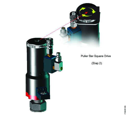
Lower the tensioner until the puller bar comes into contact with the stud.
Rotate the puller bar until the puller threads engage with the stud threads. Use a suitable 1/2” square drive manual or pneumatic wrench (preferably set at a very low torque level) engaged into the female 1/2” square drive in the top face of the puller bar. Hold the manifold block steady while rotating the puller bar; keep the manifold block and hydraulic connections in an accessible position. Be aware that the tool outer body will want to rotate with the puller bar. Continue rotation until the base of the tool makes contact with the joint face.

If the tool fails to make contact with the joint face remove the tensioner and check that the stud protrusion is within tolerance. Please refer to the general arrangement drawing of the tensioner, which states the minimum and maximum stud protrusion required.
Once the tensioner is fully assembled on the joint, reposition the 1/2” square wrench to engage in the gearbox square drive and rotate the nut rotation shaft. The spring-loaded nut-rotating socket will snap down and engage correctly with the hexagon nut.


Failure to comply with this procedure will lead to a damaged and inoperable gearbox mechanism. The applied torque on the pinion drive must not exceed 30Nm
Repeat steps 1 to 4 until the bolts to be tensioned are all fitted with bolt tensioners.
Required Stud Protrusion

Fitting of the Hydraulic Harness
It is essential that all hoses be fitted correctly with coupling locking collars tightened. Connect the tensioner/s to a suitable pump unit. Assemble the harness as shown in the below drawing
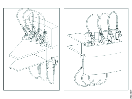
Typical hydraulic hose assembly arrangement. Illustrated for both inner and outer tower bolts.
Operation
Operating Instructions
Bolt Tensioning Tensioner Removal
Ensure that all pistons have fully retracted. Make sure the top of the puller bar is flush with the top of the endcap.
Unscrew the puller bars by rotating the puller bar until the puller threads disengage with the stud threads. Use a suitable 1/2” square drive manual or pneumatic wrench (preferably set at a very low torque level) engaged into the female 1/2” square drive in the top face of the puller bar. Hold the manifold block steady while rotating the puller bar; keep the manifold block and hydraulic connections in an accessible position. Be aware that the tool outer body will want to rotate with the puller bar. Once the threads have fully disengaged lift the tools away from the bolts.
Optional Procedure - Break Loose Check
In order to determine the retained load in a tensioned bolt it is possible to re-tension the bolt, and during the pressurisation sequence constantly monitor for the pressure point that the bolted joint hexagon or round nut comes loose.
It is normal to use a single bolt tensioner when completing a break loose check.
Assemble the tensioner on the pre-tensioned bolt, see also Installation of the Aero WTB Tool
Connect the tensioner to the tensioning pump using a single Atlas Copco hydraulic link hose.
Insert the torque ratchet handle into the square drive of the nut rotating gearbox.
Start the tensioning pump unit. The pump will start to run and pressure will build up slowly in the system. As the pressure builds, constantly apply a hand torque to the torque ratchet wrench in an anti clockwise direction. Constantly monitor for the pressure that the nut rotating gearbox shaft begins to freely rotate. This free rotation of the gearbox shaft in an anti-clockwise direction indicates that the tensioner has exceeded the load that was originally retained in the bolt. Immediately stop the pump unit and make note of the break loose pressure.
Once the break loose pressure has been noted, continue to pressurise the tensioner to the original specified working pressure.
When the original specified pressure is achieved, stop the pump, the pressure should hold steady.
Tighten the nuts down against the joint face using the square drive on the gearbox shaft. Turn the shaft clockwise to tighten.

The applied torque must not exceed 30 Nm.
Slowly release the hydraulic pressure to zero; The tensioners are fitted with an automatic reset mechanism, which allows the pistons to retract after depressurisation. Monitor the puller protruding out of the top face of the tensioner. Once the pressure is released, the puller bar will begin to withdraw into the top face of the tensioner. Only continue once the pullers are flush with the top face of the tensioner.
To ensure a good tightening result, repeat the Tensioning Operation section Steps 6 to 8.
Converting Break Loose Pressure to Break Loose Load
Multiply the Break Loose Pressure by the Hydraulic Pressure Area of the tensioner to determine achieved bolt break loose load.
Example: Using M48 WTB Tensioner HTT.11451.000, Tensioner Pressure Area = 14.025 In² and Break Loose Pressure = 10000 psi
Break Loose Load = Break Loose Pressure X Tensioner Hydraulic Pressure Area
Break Loose Load = Break Loose pressure X Tensioner Pressure Area = 10000 x 14.025 = 140250 lbs = 62.611 ton
Tensioning Operation
The following is a general tensioning procedure, which must be augmented by the wind turbine manufacturer (OEM) turbine specific assembly instructions. In each step of the general procedure where it is required to reference the OEM assembly instructions, a reference to this fact is made.
Verify that all parts are assembled correctly and all connections are properly made with coupling locking collars tightened (where available).
Start the electric pump. The pump will start to run and pressure will build up slowly in the system. Continually check the pressure. Continually check the top part of the puller bars, the protruding puller bar represents the stroke of the hydraulic pistons inside the tool. If the red over-stroke warning line becomes visible on any of the tools prior to reaching the OEM specified pressure, immediately stop the pump and refer to step 2.

While the pump is running, check the extension of the pistons. If the red over-stroke line appears, stop the pressurisation, Proceed with Steps 4 & 5 then proceed to Step 1.
When the pressure level as specified by the wind turbine OEM is reached, stop the pump, the pressure should hold steady.
Tighten the hexagon nuts down against the joint face using the square drive on the gearbox shaft.

Turn the Shaft clockwise to tighten. The applied torque must not exceed 30 Nm.
Slowly release the hydraulic pressure to zero. The tensioners are fitted with an automatic reset mechanism, which allows the pistons to retract after depressurisation. Monitor the puller protruding out of the top face of the tool. Once the pressure is released, the puller bar will begin to withdraw, so it becomes level with the top face of the tensioner again. Only continue once the pullers are flush with the top face of the tensioner.
To ensure a good tightening result, repeat the tensioning operation section step 1 up to step 5.
Transfer the tensioners to the next stud bolt. Do not disconnect the harness during this transfer.
Start the pressurisation sequence step 3 to step 7.
Before disconnecting any hoses, check that all the puller bars are flush with the top face of the tool.
Remove the hoses.
Service
Maintenance Instructions
Service Recommendations
Preventive maintenance is recommended at regular intervals. See the detailed information on preventive maintenance. If the product is not working properly, take it out of service and inspect it.
If no detailed information about preventive maintenance is included, follow these general guidelines:
Clean appropriate parts accurately
Replace any defective or worn parts
Storage Instructions
Spray the internal threads of the puller bar with a light coating of oil or a rust inhibitor.
Spray a light coat of oil or rust inhibitor to all plated surfaces for extra corrosion resistance.
Store the tensioner in an upright position.
Store the tensioner with the ram retracted
Store the tensioner in dry conditions.
Keep the dust cap on the oil inlet nipple when the tensioner is not in use.
Repair Instructions
Puller Bar Inspection Procedure
The puller bar in the centre of the aero WTB Tensioner is a highly stressed critical component and it is recommended that the condition of the component be inspected on a regular basis. Look out for:
Thread damage, both female and male threads.
Mechanical damage.
Mechanical wear.
If any damage is noted do not re-use the component, contact Atlas Copco for replacement puller bars.

Puller Bar Replacement
When ordering replacement puller bars from either bolting solutions direct or your local Atlas Copco distributor be aware that a puller bar replacement kit consists of both a puller bar and a top reaction nut pre-fitted with a locking screw. See also Puller Bar Assembly for detailed puller bar fitting instructions.
Unscrew the endcap (be aware of spring forces inside the cap).
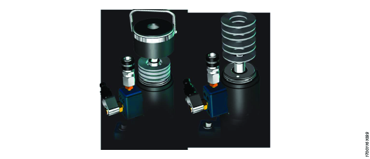
Make a note of the number and configuration of the disc springs inside the endcap and remove the disc springs.
Remove the small setscrew that holds the reaction nut to the puller bar and unscrew the reaction nut.

Withdraw the puller bar from the load cell.
Ensure the four retaining screws between spacer and bridge are tightened fully prior to using the tensioner.
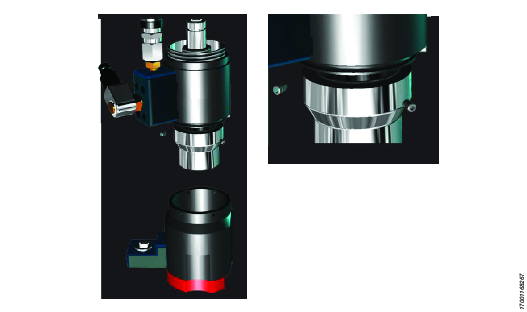
Seal replacement procedure
Unscrew the top endcap (be aware of spring forces inside the cap)
Make a note of the number and configuration of the disc springs inside the endcap and remove the disc springs.
Remove the small setscrew that holds the reaction nut to the puller bar and unscrew the reaction nut.
Remove the bridge component by unscrewing the small setscrews. Be aware of the internal spring.
Withdraw the puller bar from the load cell.
Remove the four socket head cap screws that hold the manifold block in place, remove the manifold block (there are two small seals between the manifold and load cells, keep safe for latter replacement)
Unscrew the two load cells apart, if multiple tensioners are being dis-assembled at the same time it is extremely important that pairs of load cells are kept together and are eventually re-assembled together. Load cells are matched pairs.
Using a soft material dowel, tap the Pistons out of the load cell bodies, Tap from the underside of the load cell through the bore.

It is recommended that all Seals be replaced at this time not just the failed Seal.
Using a small flat blade screwdriver prise out the seals and anti-extrusion rings from the two load cell bodies and the two pistons. Discard these seals.
Fit the Body Seal
Ensure the load cell bodies and piston are clean and free of any debris or particles.
Fit the Inner seal to the inner seal housing, in the load cell body. The triangular anti-extrusion ring cavity is to the lower of the seal housing.
Buckle the seal to allow easy fitment. Then push radially around the seal to engage the seal into the housing.

Offer the anti-extrusion ring into the extrusion ring cavity at the base of the seal. Make sure the anti-extrusion ring is in the correct orientation, it is of triangular section make sure it matches up with the triangular cavity in the seal.
Buckle the anti-extrusion ring to allow for easy fitment.
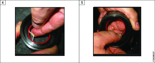
Push the anti-extrusion ring all the way around radially into the housing.
Fit the Piston Seal
Offer the anti-extrusion ring into the seal housing. The ring is of triangular section, the base of the triangle sits on the base of the seal housing.

Offer the seal into the housing above the anti-extrusion ring; insert it into the housing at one side of the piston.
Work around the diameter of the piston, pushing the seal into the housing, until the whole seal has engaged into the housing above the anti-extrusion ring.
Fit the Piston to the Lower Load Cell Body

Fit the body seal assembly tool to the lower body; ensure the tool is completely pushed down, with no gaps between the tool and the outer chamber wall of the load cell body.

Apply a smear of light grease around the chamfer machined into the seal assembly tool.
Apply a smear of light grease around the chamfer machined into the piston nose.

Offer the piston into the seal assembly Tool; insert it into the housing at one side of the Tool. Make sure the seal assembly tool stays in contact with the load cell.
Using a soft mallet tap the opposite edge of the piston into the seal assembly tool.
Working around the Piston tap the Piston fully into the Load Cell Body.

Remove the seal assembly tool.
Fit the Piston to the Upper Load Cell Body
Upper body and the inner seal assembly tool.

Offer the inner seal assembly tool into the inner seal; insert one edge first.
Apply a force to the opposite side of the assembly tool; the assembly tool will fit inside the inner seal.
Sit the outer seal assembly tool on top of the load cell.

Smear light grease around the outer seal fitting tool chamfer.
Fit the piston into the outer seal assembly tool until the seal has engaged within the chamfer.
Fit the central plug into the top bore of the piston.

Holding the outer seal assembly tool in contact with the top face of the load cell. Tap the central plug with a soft mallet until the piston outer seals enters the load cell and the nose on the piston enters the inner seal.
The inner seal assembly tool will be pushed through the inner seal and can then be removed.
Remove the top outer seal assembly tool.

Apply a force to the central plug and push the piston fully into the load cell.
Fitting the Manifold Block
Procedure also suitable for WTB tensioners fitted with an integrated mechanical counter.
Use a suitable thread locking compound.

Apply a drop into each of the four manifold fixing holes.
The manifold block.
Smear a light grease into the two seal housing grooves.

Fit two new manifold seals to the circular housing.
The grease will help to keep the small seals in position.
Carefully offer the manifold up to the assembled load cells, being careful not dislodge the two manifold seals. Lightly turn down a single socket head cap screw, do not us much torque.

Repeat with a second screw, diametrically opposite the first screw, again just gently turn down.
Repeat with a third screw adjacent to the first screw; again just gently turn the screw down.
Repeat with the final screw; again just gently turn the screw down.

Using a suitable torque handle set to break at 10Nm, tighten the first screw.
Repeat on the diametrically opposite screw, applying 10Nm.
Repeat on the screw adjacent to the first screw, applying 10Nm.

Repeat on the last screw, again applying 10Nm.
Now go back to the first screw tightened and apply a 10Nm torque. Continue around the screws in the same sequence that you originally tightened them, applying a 10Nm torque. The Manifold Block has now been fitted.
Puller Bar Assembly
A new puller bar will be supplied with a new reaction nut and a small fixing screw.

Before dis-assembly, make a note of the position of the reaction nut. The top face of the reaction nut should be in line with a step on the puller bar.

Remove the small fixing screw and unscrew the reaction nut.
Apply a lubricant to a band around the puller bar blend radius.

Apply a lubricant to the puller bar threads.
Stand the puller bar vertically and assemble the load cells onto the puller bar.
Allow the load cells to rest on the puller bar.

Screw the reaction nut onto the puller bar threads.
Rotate until the reaction nut fixing hole aligns with the fixing hole in the puller bar, the top face should be aligned with the step on the puller bar.
Fitting the Hydraulic Connections
There are many variations of hydraulic connections possible. This section of the instruction manual assumes a standard swivel connector and blanking plug configuration is to be used.
Apply a smear of thread lubricant to the blanking plug thread.

Screw the blanking plug into the top port of the manifold block.
Tighten the blanking plug. Do not over tighten.
Smear the swivel thread with thread lubricant.

Rotate the swivel connection into the front connection thread on the manifold block.
Rotate the swivel connection into the front connection thread on the manifold block. With a torque wrench, tighten to 25Nm.
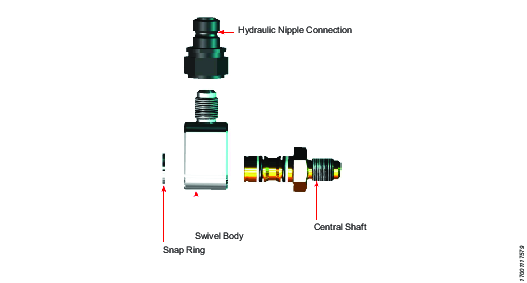
Swivel Assembly Instructions
Unscrew the swivel block from the tensioner manifold block.
Remove the snap ring from the front face of the swivel using an appropriate snap ring removal tool.
Pull out the central shaft from the swivel Block.
Remove the 2 x O Rings and 2 x anti-extrusion rings, make note of the correct fitting orientation.
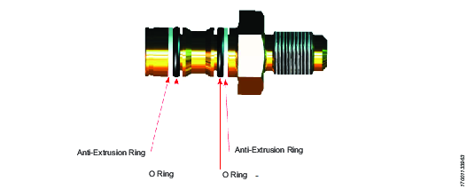
Clean central shaft and replace the failed O-rings and anti-extrusion rings and replace the O-rings and anti-extrusion rings, with new seals and anti-extrusion rings.
Using a light rubber mallet tap the central shaft back into the swivel block.
Refit the snap ring. Re-assemble the unit into the manifold block.
Fitting the Endcap & Springs
Build the stack of disc springs; it is critical that the orientation of the springs and number of springs is correct. Make a note of the number of spring and orientation during dis-assembly.

Position the endcap on a work surface and drop the correctly orientated springs into the cap.
Apply a light smear of lubricant to the male threads of the top load cell.
Still with the endcap sitting on a flat work surface. Invert the load cell assembly and screw the load cells into the endcap threads.

Once the disc springs begin to go into compression, it will be difficult to rotate the endcap by hand. At this point, lift the load cell assembly and the endcap and secure in a vice.
Using a suitable leather ratchet strap, fully rotate the endcap down until it locks against the top load cell.
The top face of the puller bar should be flush with the top face of the endcap.

Load Cell Assembly
It is important that pairs of load cells are kept together and are eventually re-assembled together. load cell assemblies are matched pairs.
Use a suitable lubricant - anti thread seizure.

Apply a smear of anti-thread seizure around the bottom load cell outer thread. Make sure this fine thread is clean and clear of debris.
Thread the two load cells together.
It may be necessary to fit two socket head cap screws to the manifold block fixing holes in order to lever the two load cells fully together.

Hold the lower load cell firmly and tap the upper load cell around until the two load cells fully butt together.
It is important that the two machined semi-circular alignment features align perfectly to make a full circle. This ensures that the manifold block will fit correctly.
Screw the two load cells tightly together until the machined alignment circle forms a full circle.

Dismantling/Assembling Instructions
Reassemble the Reaction Nut
When you receive a new puller bar replacement kit, the puller bar and reaction nut will be correctly positioned and locked together with a small setscrew. Make a note of the position of the puller bar and reaction nut position, particularly the fact that the top face of the reaction nut is “flush” with the thread shoulder of the puller bar . The reaction nut needs to be taken apart and eventually reassembled.

Remove the small setscrew locking the reaction nut to the puller bar.

Feed the puller bar up through the load cell assembly

Reassemble the reaction nut onto the puller bar taking care to screw the reaction nut down to exactly the same position as when the kit was delivered. When assembled the reaction nut should rest on the upper piston. Ensure the top face of the reaction nut is “flush” with the thread shoulder of the puller bar . Once in the correct position reassemble the small set screw, locking the reaction nut and puller bar together. The rest of the reassembly , See also Fitting the Endcap & Springs and Puller Bar Replacement.

Recycling
Environmental Regulations
When a product has served its purpose it has to be recycled properly. Dismantle the product and recycle the components in accordance with local legislation.