LZB46-RL-A025-11 ATEX
Air Motors
Product Information
General Information
Safety Signal Words
The safety signal words Danger, Warning, Caution, and Notice have the following meanings:
DANGER | DANGER indicates a hazardous situation which, if not avoided, will result in death or serious injury. |
WARNING | WARNING indicates a hazardous situation which, if not avoided, could result in death or serious injury. |
CAUTION | CAUTION, used with the safety alert symbol, indicates a hazardous situation which, if not avoided, could result in minor or moderate injury. |
NOTICE | NOTICE is used to address practices not related to personal injury. |
Warranty
Product warranty will expire 12+1 months after dispatch from Atlas Copco's Distribution Center.
Normal wear and tear on parts is not included within the warranty.
Normal wear and tear is that which requires a part change or other adjustment/overhaul during standard tools maintenance typical for that period (expressed in time, operation hours or otherwise).
The product warranty relies on the correct use, maintenance, and repair of the tool and its component parts.
Damage to parts that occurs as a result of inadequate maintenance or performed by parties other than Atlas Copco or their Certified Service Partners during the warranty period is not covered by the warranty.
To avoid damage or destruction of tool parts, service the tool according to the recommended maintenance schedules and follow the correct instructions.
Warranty repairs are only performed in Atlas Copco workshops or by Certified Service Partners.
Atlas Copco offers extended warranty and state of the art preventive maintenance through its ToolCover contracts. For further information contact your local Service representative.
For electrical motors:
Warranty will only apply when the electric motor has not been opened.
Website
Information concerning our Products, Accessories, Spare Parts and Published Matters can be found on the Atlas Copco website.
Please visit: www.atlascopco.com.
ServAid
ServAid is a portal that is continuously updated and contains Technical Information, such as:
Regulatory and Safety Information
Technical Data
Installation, Operation and Service Instructions
Spare Parts Lists
Accessories
Dimensional Drawings
Please visit: https://servaid.atlascopco.com.
For further Technical Information, please contact your local Atlas Copco representative.
Safety Data Sheets MSDS/SDS
The Safety Data Sheets describe the chemical products sold by Atlas Copco.
Please consult the Atlas Copco website for more information www.atlascopco.com/sds.
PTFE
Country of Origin
For the Country of Origin, please refer to the information on the product label.
Dimensional Drawings
Dimensional Drawings can be found either in the Dimensional Drawings Archive, or on ServAid.
Please visit: http://webbox.atlascopco.com/webbox/dimdrw or https://servaid.atlascopco.com.
Overview
IP Rating
The IP Rating of the air motors refer to the mechanical casing according to the IEC 60529 standard. The IP rating does not cover corrosion resistance or any liquids other than clean freshwater.
Technical Product Data
Technical Product Data can be found on either ServAid, or the Atlas Copco website.
Please visit: https://servaid.atlascopco.com or www.atlascopco.com.
ATEX Certification Information
Temperatures
The maximum surrounding temperature for which the certification is valid is 40°C.
40°C is also the maximum allowed temperature of the compressed air when it enters the product.
If the product is installed in an equipment, the entire equipment has to correspond to the guidelines 2014/34/EU.
Make sure that the compressed air fulfil our quality demands (quality classes 2.4.3. and 3.4.4 respectively 3.5.4 acc. to ISO/DIS 8573-1:2010).
Do not exceed maximum pressure of 6.3 bar, or as stated on the product nameplate. Exceeding the operating pressure can increase the surface temperature due to higher rotating speed and the product can become an ignition source.
Ex Classification
If the product is part of an assembly where the components have different Ex classification, the component with the lowest level of safety defines the Ex classification of the complete assembly.
ATEX Code Definition
The ATEX code is: | |
|---|---|
Ex II 2 G Ex h IIC T4 Gb Ex II 2 D Ex h IIIC T110°C Db °C ≤ Ta ≤ 40 °C | |
Description | Value | Definition |
|---|---|---|
Equipment group | II | Surface Industry |
Equipment category Group II | 2 | High level of protection
|
Atmosphere
| G | Atmosphere containing Gas, Vapors or Mist |
D | Atmosphere containing Dust | |
Safety design | h | Mechanical product |
Gas group | IIC | Hydrogene/ Acetylene |
IIB | Ethylene | |
Dust group | IIIC | Surface combustible dust |
Max surface temperature in Gas atmosphere |
| T1 = 450°C T2 = 300°C T3 = 200°C T4 = 135°C T5 = 100°C T6 = 85°C |
Max surface temperature in Dust atmosphere |
| Example temperatures: T85°C T110°C T120°C T125°C T240°C |
Special restriction, for example ambient temperature range. | X |
Explosion Prevention Guidelines
Cleanliness
-
Make sure the product is kept clean from dust and dirt to prevent increased bearing and surface temperature.
-
If using a silencer: Make sure a silencer with a filtering effect at the air outlet is installed to prevent any friction-heated particles entering into the surrounding atmosphere.
Usage
-
Make sure the product is earthed to the equipotential bonding system of the workshop, for example through accessories such as hoses and air-pressure connections.
-
It is the responsibility of the user to make sure that the product and all possible accessories, such as wrenches and air connections, conform to the national safety regulations for equipment used in potentially explosive areas.
Installation
Installation Requirements
Air Quality
For optimum performance and maximum product life we recommend the use of compressed air with a maximum dew point of +10°C (50°F). We also recommend to install an Atlas Copco refrigeration type air dryer.
Use a separate air filter which removes solid particles larger than 30 microns and more than 90% of liquid water. Install the filter as close as possible to the product and prior to any other air preparation units to avoid pressure drop.
For impulse/impact tools make sure to use lubricators adjusted for these tools. Regular lubricators will add too much oil and therefore decrease the tool performance due to too much oil in the motor.
Make sure that the hose and couplings are clean and free from dust before connecting to the tool.
Both lubricated and lubrication free products will benefit from a small quantity of oil supplied from a lubricator.
Air lubrication
|
Brand |
Air lubrication |
|---|---|
|
Mobil |
Mobil SHC Cibus 32 |
Compressed Air Connection
For correct air pressure and hose size, see the Technical Product Data on - https://servaid.atlascopco.com or www.atlascopco.com.
Make sure that the hose and couplings are clean and free from dust before connecting to the tool.
Shaft Load Diagram

Shaft Load
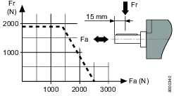
Make sure that the maximum shaft load is not exceeded, in order to prevent an excessive increase of the bearing temperature.
Installation Instructions
Connecting the Air Supply
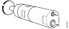
When the compressed air supply is connected to the inlet, the direction of rotation will be as shown in the figure below. If the exhaust air is to be piped away, a hose should be connected to the exhaust outlet.

Installation Diagram
Non-Reversible motor

IP Rating
The IP Rating of the air motors is set under pressurized condition and excludes the outlet or attached silencer. If the motor will operate submerged or in heavy water jets, it's recommended to lead the outlet away from water with a hose. When submerged, always keep the motor pressurized with a higher pressure than the corresponding depth.
Operation
Ergonomic Guidelines
Consider your workstation as you read through this list of general ergonomic guidelines and see if you can identify areas for improvement in posture, component placement, or work environment.
Take frequent breaks and change work positions frequently.
Adapt the work area to your needs and the work task.
Adjust for convenient reach range by determining where parts or tools should be located to avoid static load.
Use workstation equipment such as tables and chairs appropriate for the work task.
Avoid work positions above shoulder level or with static holding during assembly operations.
When working above shoulder level, reduce the load on the static muscles by reducing the weight of the load. You can also reduce the load on the static muscles by holding the load close to the body.
Make sure to take frequent breaks.
Avoid extreme arm or wrist postures, particularly for operations requiring a degree of force.
Adjust for convenient field of vision by minimizing movement of the eyes and head during the work task.
Use the appropriate lighting for the work task.
Use ear protection equipment in noisy environments.
Use dust extraction system or mouth protection mask in dusty environments.
Operating Instructions
Hot Spots
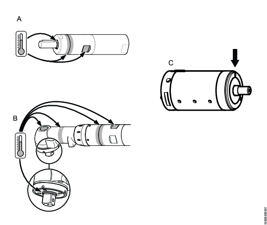
The following hot spots on the motor can reach high temperatures during operation. The image shows hot spots for specific models:
Seal ring at the output shaft (A, B, C)
Joint between front part and gear ring (A, B)
Key grip (A, B)

The highest temperatures occur when the motor is running at full pressure without load. With increasing torque, the air motor reduces the rotational speed and the temperature.
Service
Maintenance Instructions
Service Recommendations
Preventive maintenance is recommended at regular intervals. See the detailed information on preventive maintenance. If the product is not working properly, take it out of service and inspect it.
If no detailed information about preventive maintenance is included, follow these general guidelines:
Clean appropriate parts accurately
Replace any defective or worn parts
Overhaul
To achieve the best engine service life under normal operating conditions, regular overhaul and cleaning should be carried out every 12 months or after every 1000 hours (without lubricated air) or 2000 hours (with lubricated air) of operation, whichever is the sooner. Overhaul should be carried out more frequently under more rigorous operating conditions.
Clean the engine thoroughly.
Fit the engine and check that it rotates freely. Pour two drops of oil into the air intake and idle the engine for 5–10 seconds.
If the compressed air is very dry, the idle speed for lubricant-free engines may decrease slightly after fairly long periods of operation. This decrease may amount to 10–15%.
Maintenance
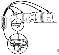
Maintenance and repairs of this ATEX product must be carried out exclusively by authorised personnel, after which a no-load test and temperature measurements of hotspots (as seen in the figure) must be carried out and recorded in a report.
After a 5 min no-load test the surface temperature must not exceed the sum of 70°C + surrounding temperature, where the surrounding temperature can vary between 0 – 40°C.


Lubrication Instructions
Rust Protection and Cleaning
Water in the compressed air can cause rust. To prevent rust we strongly recommend to install an air dryer.
Water and particles can cause sticking of vanes and valves. This can be prevented by installing an air filter close to the product to avoid pressure drop.
Before longer stand stills always protect your tool by adding a few drops of air motor oil into the air inlet. Run the tool for 5–10 seconds and absorb any excess oil at the air outlet in a cloth.
Grease Guide
Brand | General purpose, Bearings and Gears | Note |
|---|---|---|
Mobil | Mobil SHC Polyrex 222 | Food grade approved |
Lubrication
Planetary gears, ball- and needle bearings and seal ring should be lubricated with grease in conjunction with the regular overhaul of the motor.
Always use lubricants of good quality. The oils and greases mentioned in the chart are examples of lubricants which are recommended.
Recycling
Environmental Regulations
When a product has served its purpose it has to be recycled properly. Dismantle the product and recycle the components in accordance with local legislation.
Batteries shall be taken care of by your national battery recovery organization.
Recycling information

|
Part: |
Recycle as: | |
|---|---|---|
|
1 |
Gear module |
Stainless steel |
|
2 |
Vane motor complete |
Steel* |
|
3 |
Casing |
Stainless steel |
*The rotor blades (vanes) in the product contains PTFE, the normal health and safety recommendations concerning PTFE must be observed.
Recycling information

Part: | Recycle as: | |
|---|---|---|
1 | Gear module | Metal, Stainless steel |
2 | Vane motor complete | Metal, Steel* |
3 | Casing | Metal, Stainless steel |
*The rotor blades (vanes) in the product contains PTFE, the normal health and safety recommendations concerning PTFE must be observed.
