ACHS28T Flange Spreader
Product Information
General Information
Safety Signal Words
The safety signal words Danger, Warning, Caution, and Notice have the following meanings:
DANGER | DANGER indicates a hazardous situation which, if not avoided, will result in death or serious injury. |
WARNING | WARNING indicates a hazardous situation which, if not avoided, could result in death or serious injury. |
CAUTION | CAUTION, used with the safety alert symbol, indicates a hazardous situation which, if not avoided, could result in minor or moderate injury. |
NOTICE | NOTICE is used to address practices not related to personal injury. |
Warranty
Product warranty will expire in 12+1 months after dispatch from Atlas Copco's Distribution Center.
Normal wear and tear on parts is not included within the warranty.
Normal wear and tear is that which requires a part change or other adjustment/overhaul during standard tool maintenance typical for that period (expressed in time, operation hours or otherwise).
The product warranty relies on the correct use, maintenance, and repair of the tool and its component parts.
Damage to parts that occurs as a result of inadequate maintenance or performed by parties other than Atlas Copco or their Certified Service Partners during the warranty period is not covered by the warranty.
To avoid damage or destruction of tool parts, service the tool according to the recommended maintenance schedules and follow the correct instructions.
Warranty repairs are performed only in Atlas Copco workshops or by Certified Service Partners.
Atlas Copco offers extended warranty and state-of-the-art preventive maintenance through its ToolCover contracts. For further information, contact your local Service representative.
For electrical motors:
Warranty will apply, only when the electric motor has not been opened.
Website
Information concerning our Products, Accessories, Spare Parts and Published Matters can be found on the Atlas Copco website.
Please visit: www.atlascopco.com.
ServAid
ServAid is a portal that is continuously updated and contains Technical Information, such as:
Regulatory and Safety Information
Technical Data
Installation, Operation and Service Instructions
Spare Parts Lists
Accessories
Dimensional Drawings
Please visit: https://servaid.atlascopco.com.
For further Technical Information, please contact your local Atlas Copco representative.
Safety Data Sheets MSDS/SDS
The Safety Data Sheets describe the chemical products sold by Atlas Copco.
Please consult the Atlas Copco website for more information www.atlascopco.com/sds.
Country of Origin
For the Country of Origin, please refer to the information on the product label.
Dimensional Drawings
Dimensional Drawings can be found either in the Dimensional Drawings Archive, or on ServAid.
Please visit: https://webbox.atlascopco.com/webbox/dimdrw or https://servaid.atlascopco.com.
Overview
Technical Data
Ordering No | 8434244293 |
Spreading force [kN] | 277 |
Spreading force [ton] | 27.80 |
Spreading distance w/o stepped blocks min [mm] | 5 |
Spreading distance w/o stepped blocks min [in] | 0.197 |
Spreading distance w/o stepped blocks max [mm] | 74 |
Spreading distance w/o stepped blocks max [in] | 2.913 |
Max working pressure [bar] | 700 |
Max working pressure [psig] | 10000 |
Spreading distance with stepped blocks min [mm] | 55 |
Spreading distance with stepped blocks min [in] | 2.165 |
Spreading distance with stepped blocks max [mm] | 124 |
Spreading distance with stepped blocks max [in] | 4.882 |
Product Description
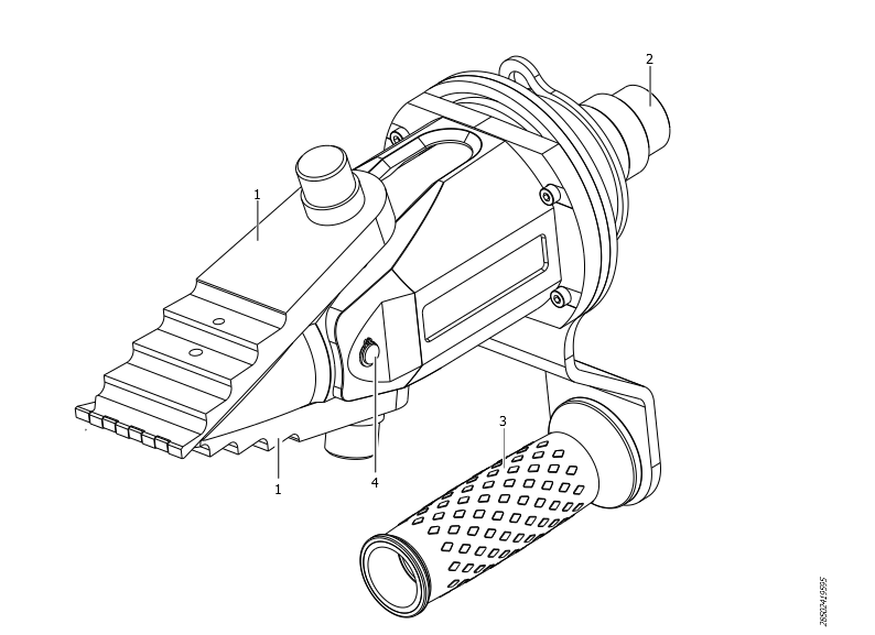
1 | Jaws | 2 | Coupler |
3 | Handle | 4 | Pin |
Applications
Flange Spreading Wedges are designed to open flange joints with a minimum access gap of 5 mm.
The jaws of the tool open in a parallel motion which maintains a safe along with full step contact between the tool and the flange.
The parallel Jaw motion also ensures that the spreading forces are perpendicular to the flange face.
It is highly recommended that two or more Flange Spreading Wedges are used together to maintain a parallel Flange joint gap during spreading.
Technical Product Data
Technical Product Data can be found on either ServAid, or the Atlas Copco website.
Please visit: https://servaid.atlascopco.com or www.atlascopco.com.
Operation
Ergonomic Guidelines
Consider this list of general ergonomic guidelines to identify areas for improvement in posture, handling or work environment.
Take frequent breaks and change work positions frequently.
Adapt the workstation area to your needs and the work task.
Adjust for a convenient reach range by determining where tools need to be located to avoid static load.
Avoid work positions above shoulder level or with static holding during assembly operations.
When working above shoulder level, reduce the load on the static muscles by lowering the weight of the tool, using for example torque arms, hose reels or weight balancers. You can also reduce the load on the static muscles by holding the tool close to the body.
Take frequent breaks.
Avoid extreme arm or wrist postures, particularly during operations requiring a degree of force.
Adjust for a convenient field of vision that requires minimal eye and head movements.
Use appropriate lighting for the work task.
Select the appropriate tool for the work task.
In noisy environments, use ear protection equipment.
Operating Instructions
Operating the Pump
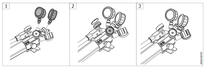


Connect the gauges to the pump.

Make sure the control valves are closed.
Remove the caps from the connectors.
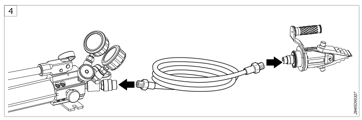
Connect the hose to the pump and to the tool.
Close the pressure relief valve.
Open the control valves simultaneously to apply the pressure on the connect tools.
Use the handle to build the pressure in the pump.
The safe working pressure must be 10,000 psi (700 Bar).
Close one control valve, to increase the pressure on one active tool.
Depressurizing the Pump
Open both control valves slowly.
Open the pressure relief valve to depressurize the system.
Check the gauges and make sure the pump is depressurized before disconnecting the coupling.
Operating the Flange Spreader
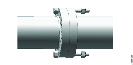

Before operating the tool for flange joint, check the minimum access gap should be 5 mm.
Insert the first flange spreader into the flange Joint access gap.
Insert the second flange spreader into the flange joint access gap.
Make sure the tool is fully inserted.
Operate the pump handle to pressurize the system. Refer to Operating the Pump.

Once the required gap is formed into the flange joint, insert the safety block.
Insert the safety blocks on both sides of the flange joint.
Release the pressure and depressurize the system. Refer to Operating the Pump.
The operator may perform the flange work now.
Close the flange joint after the work is finished.
Depressurize the system after the work is finished.
Service
Maintenance Instructions
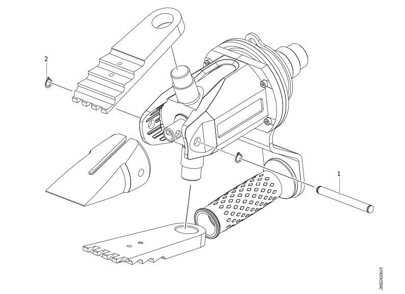
Attaching the Stepped Block and Larger Safety Block

A stepped block can be attached to the tool to increase the spreading distance.
Use the retaining screw and hex key provided to attach the stepped block (1).
A second stepped block can be attached to increase the spreading distance to a maximum of 124 mm (4.88 ”).
When the tool is used with stepped blocks the large safety block must be used.
Unscrew and remove the top block from the small safety block.
Attach the top block on to the large safety block (2) and tighten the screw.
Maintenance Instructions
Service Recommendations
Preventive maintenance is recommended at regular intervals. See the detailed information on preventive maintenance. If the product is not working properly, take it out of service and inspect it.
If no detailed information about preventive maintenance is included, follow these general guidelines:
Clean appropriate parts accurately
Replace any defective or worn parts
Maintenance
Visually Inspect the tool, jaws, wedge and coupler for any damage.
Replace the worn or damaged parts
Clean and remove the access grease from the surfaces and coupler
Clean the coupler and put the protective cover.
Apply the grease to the tool jaws (1) with a high load bearing grease.

Repair Instructions
Spare Parts List

Ordering No. | Item No. | Description | Qty |
|---|---|---|---|
4222911839 | 1 | Driven Wedge | 1 |
4222911840 | 2 | Shroud | 1 |
4222911841 | 3 | Handle Bracket | 1 |
4222911842 | 4 | Handle Backing Plate | 1 |
4222911843 | 5 | Lanyard Ring | 1 |
4222911844 | 6 | Spiral Retaining Ring | 1 |
4222911845 | 7 | Driven Wedge Pin | 1 |
4222911846 | 8 | Driven Wedge Pin External Circlip | 2 |
4222911864 | 9 | Tool Body Asembly | 1 |
4222911865 | 10 | Jaw Assembly (Pair) | 1 |
4175070590 | 11 | Handle | 1 |
4222912241 | 12 | M4 x 18 LG Socket Head Cap Screw | 4 |
Dismantling/Assembling Instructions
Disassembly of the Tool
Remove the pin (1) and the circlip (2).
The jaws are disassembled from the tool.
Recycling
Environmental Regulations
When a product has served its purpose it has to be recycled properly. Dismantle the product and recycle the components in accordance with local legislation.
Batteries shall be taken care of by your national battery recovery organization.