C8-05
Tensioner
Product Information
General Information
Safety Signal Words
The safety signal words Danger, Warning, Caution, and Notice have the following meanings:
DANGER | DANGER indicates a hazardous situation which, if not avoided, will result in death or serious injury. |
WARNING | WARNING indicates a hazardous situation which, if not avoided, could result in death or serious injury. |
CAUTION | CAUTION, used with the safety alert symbol, indicates a hazardous situation which, if not avoided, could result in minor or moderate injury. |
NOTICE | NOTICE is used to address practices not related to personal injury. |
Warranty
Product warranty will expire 12+1 months after dispatch from Atlas Copco's Distribution Center.
Normal wear and tear on parts is not included within the warranty.
Normal wear and tear is that which requires a part change or other adjustment/overhaul during standard tools maintenance typical for that period (expressed in time, operation hours or otherwise).
The product warranty relies on the correct use, maintenance, and repair of the tool and its component parts.
Damage to parts that occurs as a result of inadequate maintenance or performed by parties other than Atlas Copco or their Certified Service Partners during the warranty period is not covered by the warranty.
To avoid damage or destruction of tool parts, service the tool according to the recommended maintenance schedules and follow the correct instructions.
Warranty repairs are only performed in Atlas Copco workshops or by Certified Service Partners.
Atlas Copco offers extended warranty and state of the art preventive maintenance through its ToolCover contracts. For further information contact your local Service representative.
For electrical motors:
Warranty will only apply when the electric motor has not been opened.
Website
Information concerning our Products, Accessories, Spare Parts and Published Matters can be found on the Atlas Copco website.
Please visit: www.atlascopco.com.
ServAid
ServAid is a portal that is continuously updated and contains Technical Information, such as:
Regulatory and Safety Information
Technical Data
Installation, Operation and Service Instructions
Spare Parts Lists
Accessories
Dimensional Drawings
Please visit: https://servaid.atlascopco.com.
For further Technical Information, please contact your local Atlas Copco representative.
Safety Data Sheets MSDS/SDS
The Safety Data Sheets describe the chemical products sold by Atlas Copco.
Please consult the Atlas Copco website for more information www.atlascopco.com/sds.
Country of Origin
For the Country of Origin, please refer to the information on the product label.
Dimensional Drawings
Dimensional Drawings can be found either in the Dimensional Drawings Archive, or on ServAid.
Please visit: http://webbox.atlascopco.com/webbox/dimdrw or https://servaid.atlascopco.com.
Overview
Product Overview
Main Components
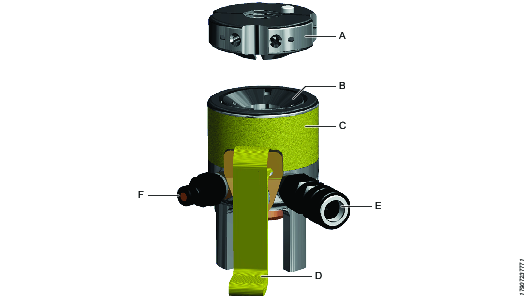
Part Identifier | Description |
|---|---|
A | Quick Split Reaction Nut |
B | Piston |
C | Tensioner Body |
D | Lifting Strap |
E | Female Hydraulic Connection (configuration may vary) |
F | Male Hydraulic Connection (configuration may vary) |
Separate Split Reaction Nut

The split reaction nut is a completely separate component and is assembled onto the bolt after the tensioner has been fitted.
Technical Product Data
Technical Product Data can be found on either ServAid, or the Atlas Copco website.
Please visit: https://servaid.atlascopco.com or www.atlascopco.com.
Accessories
Split Nut Applicability
Tensioner Thread Size | Split Nut Product No. | Split Nut Thread Size |
|---|---|---|
C8-05 | 8434220037 | 2-1/4" |
8434220038 | 2-1/2" | |
8434220039 | M56 x 5.5 | |
8434220040 | M60 x 5.5 | |
8434220041 | M64 x 6 |
Installation
Installation Instructions
Set-up Preparations
Prior to connecting the hydraulic pump to any bolt tensioning equipment, ensure that:
The working pressure of the hydraulic pump and the equipment to be operated are compatible.
The reservoir pump capacity is adequate to operate the equipment throughout its range.
The hydraulic oil specification used within the pump and the equipment are compatible.
The technical specifications of the tensioning tool is known.
Ensure sufficient stud protrudes above the hexagon or round joint nut.
Hydraulic Hose Fitting
Using link hoses, interconnect each of the tensioners on one side of the flange. Connect the hydraulic downline to an unconnected male connector. Ensure there is an unconnected female connection available after hose assembly.
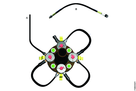
A
Downline hose to the surface and the air driven pump
B
Typical hydraulic link hose
Interconnect each of the tensioners on the other side of the flange. Ensure there is a unconnected male connector and an unconnected female connection available.
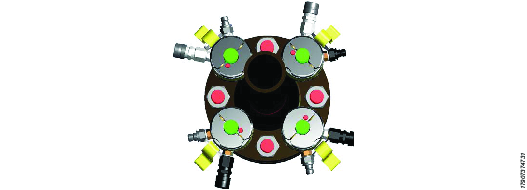

Connect the two sides of the flange together with the supplied cross-over link hose, the crossover link hose is identical to the link hoses but it is longer. Connect the cross-over link hose from the female connection on the first flange side to the free male connector on the second flange side.

A
Flange side 1
B
Flange side 2
C
Cross-over link hose
If the hydraulic hose system is fitted correctly, there will be a single FEMALE unconnected connection on flange side 2. This is correct and safe. It is SAFE to pressurize an unconnected female connection. It is however UNSAFE to have an unconnected male connector. If you are left with an unconnected male connection, check the hydraulic link hose assembly and correct the error.
Split Reaction Nut Usage
The split reaction nut is a completely separate component and is assembled onto the bolt after the tensioner has been fitted.
Position the split reaction nut over the bolt.

Press the nut release button to snap the split reaction nut into the ‘open’ position. The two halves of the split reaction nut will spring apart.

Position the split reaction nut over the stud protrusion.

Squeeze the two halves of the split nut together, after placing them on the top face of the tensioning tool. A ‘click’ can be heard when the two halves click into their closed position.

Using a Tommy Bar slotted into the a slot of the split reaction nut, rotate the reaction nut downwards until it engages fully into the tensioner's coned seat.

Before tensioning begins, ensure at least three threads is protruding above the split reaction nut when the split reaction nut is fully engaged into the coned seat in the top face of the tensioning tool.

A: At least three threads should protrude from the top of the split reaction nut.
Never load a split reaction nut that has not ‘clicked’ into its fully closed position.
Never load a split reaction nut that has not got full thread engagement throughout its full length.
Repeat direct reverse assembly procedure when disassembling.
Bolt Set-up
In order to apply an evenly distributed load to a subsea bolted joint, it is accepted that a 100% tensioner to bolt ratio is required. I.e if 8 bolts are on the flange to tension, 8 bolt tensioning tools are required. All bolts are simultaneously tensioned.
The correct bolt set up for a 8 bolt flange.
Examples:
6 bolt flange requires 6 bolt tensioning tools.
8 bolt flange requires 8 bolt tensioning tools.
Pay attention on how each bolt is set up with the long stud protrusion on every alternate bolt. The long stud protrusion side is the side where the bolt tensioning tool is fitted.
In this case, the 4 alternate red bolts will have tensioners fitted to the left side of the flange, and the 4 alternate green bolts will have tensioners fitted to the right hand side of the flange.

A | 4 Tensioning tools are fitted to the left side of the flange. | B | 4 Tensioning tools are fitted to the right side of the flange. |
Technical Specification
The technical specification of your particular bolt tensioning tools can be found hard stamped on the tensioner body.
Bolt Set-up Procedure
Ensure the flanges are fully engaged and that the bolts and nuts are tightened. Assemble 50% of the bolt tensioning tools over the ‘long’ bolt extensions on one side of the flange.
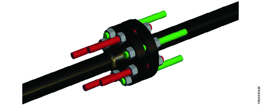
Ensure at least three threads protrudes above the top face of the reaction nut after fitting.

A
At least three full threads should protrude from the reaction nut after fitting
Ensure the flanges are fully pulled together and that the bolts and nuts are tightened down. Assemble the other 50% of the bolt tensioning tools over the ‘long’ bolt extensions on the other side of the flange.

Ensure at least three threads protrudes above the top face of the reaction nut after fitting.
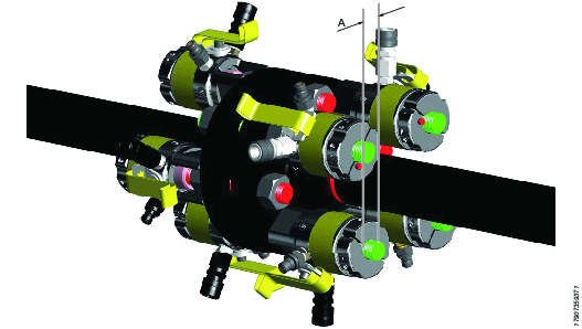
A
At least three full threads should protrude from the reaction nut after fitting
Examine the circumference of the tensioner base to ensure it is sitting fully flat against the tensioning surface.
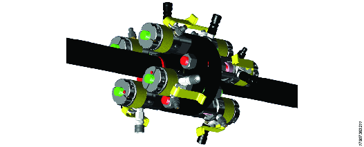

Operation
Operating Instructions
Bolt Tensioning Procedure
Before applying pressure to the system
Read and understand the Safety Instructions that comes with the product.
Make sure you are aware of the correct operation of the hydraulic pump unit.
Make sure you are aware of the maximum working pressure of the tensioner.
Make sure you are aware of the maximum piston movement of the tensioner (See hard stamped on tensioner loadcells).
Make sure you are aware of the required working pressure that must be applied to the tensioner.
Lifting eyes and straps on tools should be checked before usage. Check for cracks or any other visible damage. Lifting straps or eyebolts which are found to be damaged should not be used.
Ready to Tension
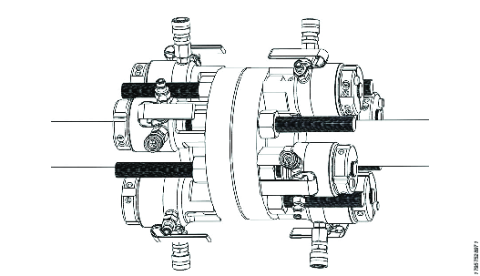
In the following illustrations the hydraulic link hoses have been removed for reasons of clarity.
Close the stop valve on the pump unit, then pressurize the system to the required pressure. Monitor the pressure continuously throughout the process. When the target pressure is reached, stop the pump (Hold Pressure). At this stage the bolt will be initially loaded with the load being held by the tensioner. The tensioner piston will be extended and the flange nut will rise off the flange surface.
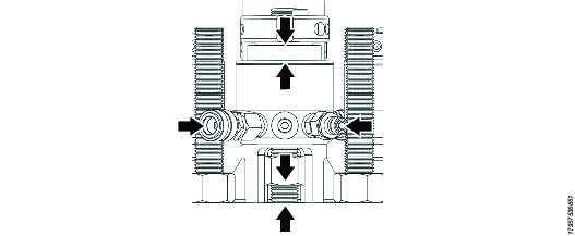
Do not exceed the maximum piston stroke of the tensioner (a red band will become visible as maximum piston stroke is approached).

Check the pump gauge to ensure the pressure is holding firmly. When the pressure is stable, approach the tensioner and by using the tommy bar; rotate the nut, (through the tensioner access windows), back down towards the joint face. Seat the nut firmly against the joint, by the use of a mallet and tommy bar. If the nut is not seated firmly, the tensioning procedure will take much longer to complete. It is not important in which order the nuts are tightened but to be sure of not missing one, it is recommended they are tightened in sequence.


Now repeat the tensioning procedure from Step 1. The first pressurization was used to ‘bed’ the flange bolts and nuts. This is useful in order to maximize the amount of retained bolt load. Repeat from Step 1 a third time.
Release the pressure at the Hydraulic Pump Unit and once the oil has returned disconnect all of the hydraulic link hoses, cross-over link hose and down line. Release the split reaction nut and remove all the bolt tensioning tools.
Once the tensioning equipment is deployed topside, close all the piston rams, ready for next usage.
De-Tensioning Procedure
When de-tensioning, specific tool pressures are not normally available as it is not always possible to calculate the pressure at which the flange nut will break free. As a guide, if the original flange bolt tightening pressures are available, the de-tensioning pressure is usually marginally higher than the original tensioning pressure (but not always).
The maximum pressure that can be applied has been calculated to ensure that either 95% of the bolt material yield is not exceeded, or the maximum tool pressure is not exceeded, whichever is the lower. Pump must be pre-set to achieve this.
Assemble the tensioning tools to the bolts. With the reaction nut fully screwed down and seated on the piston, unscrew the reaction nut one and a half turns. This will prevent the reaction nut from becoming locked onto the piston when the bolt tension is released.
Insert a tommy bar through the tensioner access window and into a hole in the flange hexagon nut. Apply hydraulic pressure to the system until the flange nut can be rotated, ensuring that the piston does not exceed maximum stroke or system pressure does not exceed maximum pressure allowed.
Turn back each flange nut one full turn.
De-pressurize the system and check to see that the flange nuts are still free to rotate.
Remove the bolt tensioners.
Service
Seal Replacement S2/K2 Type
Atlas Copco use different seal configurations due to differences in tensioner specifications and tensioner usage environments. This section details the replacement of S2/K2 type high pressure seals.
Make note of the correct orientation of the triangular backup ring.

Put the outer backup ring into the piston outer seal housing.
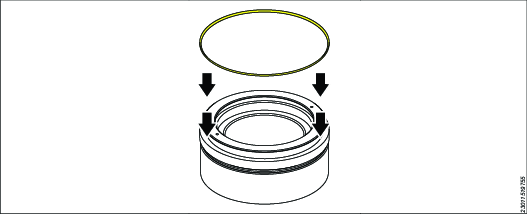
Position and stretch the outer seal into the piston outer seal housing.
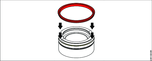
The seal fits above the backup ring.
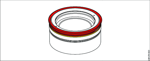
With a rounded smooth screwdriver, push the seal until the seal clips into the seal housing.
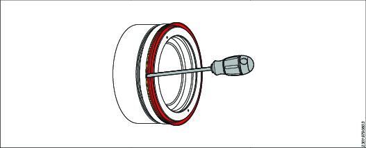
Make sure that the seal and backup ring are fully seated around circumference.

Squeeze the inner seal into the inner seal housing.

Push the inner seal in place with a smooth rounded screwdriver.

Put the inner backup ring below the inner seal.

Carefully bend the backup ring to enable it to clip into position. Make sure that the seal and backup ring are fully seated around the circumference.

Maintenance Instructions
Service Recommendations
Preventive maintenance is recommended at regular intervals. See the detailed information on preventive maintenance. If the product is not working properly, take it out of service and inspect it.
If no detailed information about preventive maintenance is included, follow these general guidelines:
Clean appropriate parts accurately
Replace any defective or worn parts
Preservation and Storage
Subsea tensioners are made of Stainless Steel with an additional electrolysis nickel finish. They are corrosion and wear resistant and under suitable conditions will not rust.
Any tools which are exposed to salt water should be rinsed with fresh water and dried before storage.
Tools which have been exposed to water during usage (from rain or similar) should be throughly dried before storage. Once packed, all accessible surfaces of the tools should be sprayed with a suitable non-drying rust prohibitive oil (for example, Shell Ensis Fluid or Castrol Rustillo DW300X).This is to ensure that the tools remain rust through their service life.
During storage, it is recommended that all hydraulic fittings have their connected dust caps correctly fitted to prevent any foreign objects getting into the fittings and fouling them.
The packing crates that are provided as a standard are not water tight and should be covered (under a waterproof tarpaulin or plastic sheeting, for example) if used for longer term storage. The packing crates will protect against incidental splashes but are not designed for constant wet conditions.
Pack the tools into the crate with suitable packing material to prevent the tools from sliding around.
Tensioner Maintenance
Always wear impact-resistant eye and face protection when involved with or near the operation, repair or maintenance of the tool or changing accessories on the tool.
Disconnect the power supply and depressurize the hydraulic system before disconnecting or connecting hoses, fittings, or accessories or adjusting or dismantling the tool.
During assembly and maintenance of the tensioning tools, threaded components should be lubricated and protected with a thin coating of anti-sieze compound such as Copaslip or Molyslip in order to prevent rust forming on the screw threads and additionally prevent threaded components from seizing together during use.
Prior to installation, the seals, the bearing strips and wiper seals should have the leading edges lubricated with a suitable light grease, such as Rocol Aqua-Sil. This will aid assembly.
The tool should be fully refurbished once every 12 months.
Inspected for any signs of corrosion. Tools that have evidence of corrosion should be returned to Customer Center.
After every use: check for any oil weeping from the fitting or the adaptor pieces. Any adaptors or fittings that are leaking should be tightened to 25 Nm. Any adaptor or fitting that continues to leak after being tightened should be replaced.
Lifting eyes and straps on tools should be checked before usage. Check for cracks or any other visible damage. Lifting straps or eyebolts which are found to be damaged should not be used.
The tool should not be dropped or hit by other objects as this might cause damage to the sealing surfaces of the tool, which can result in tool failure during usage.
The tool coating should be routinely inspected and checked for any evidence of cracking or flaking. It is recommended that tools that have evidence of flaking or cracking should be returned to Customer Center.
If at any time you have doubts about the operational suitability, please contact Atlas Copco Customer Center for advice.
Recycling
Environmental Regulations
When a product has served its purpose it has to be recycled properly. Dismantle the product and recycle the components in accordance with local legislation.