Product Information
General Information
Safety Signal Words
The safety signal words Danger, Warning, Caution, and Notice have the following meanings:
DANGER | DANGER indicates a hazardous situation which, if not avoided, will result in death or serious injury. |
WARNING | WARNING indicates a hazardous situation which, if not avoided, could result in death or serious injury. |
CAUTION | CAUTION, used with the safety alert symbol, indicates a hazardous situation which, if not avoided, could result in minor or moderate injury. |
NOTICE | NOTICE is used to address practices not related to personal injury. |
Warranty
Product warranty will expire 12 months after the product is first taken into use, but will in any case expire at the latest 13 months after delivery.
Normal wear and tear on parts is not included within the warranty.
Normal wear and tear is that which requires a part change or other adjustment/overhaul during standard tools maintenance typical for that period (expressed in time, operation hours or otherwise).
The product warranty relies on the correct use, maintenance, and repair of the tool and its component parts.
Damage to parts that occurs as a result of inadequate maintenance or performed by parties other than Atlas Copco or their Certified Service Partners during the warranty period is not covered by the warranty.
To avoid damage or destruction of tool parts, service the tool according to the recommended maintenance schedules and follow the correct instructions.
Warranty repairs are only performed in Atlas Copco workshops or by Certified Service Partners.
Atlas Copco offers extended warranty and state of the art preventive maintenance through its ToolCover contracts. For further information contact your local Service representative.
For electrical motors:
Warranty will only apply when the electric motor has not been opened.
Website
Information concerning our Products, Accessories, Spare Parts and Published Matters can be found on the Atlas Copco website.
Please visit: www.atlascopco.com.
ServAid
ServAid is a portal that is continuously updated and contains Technical Information, such as:
Regulatory and Safety Information
Technical Data
Installation, Operation and Service Instructions
Spare Parts Lists
Accessories
Dimensional Drawings
Please visit: https://servaid.atlascopco.com.
For further Technical Information, please contact your local Atlas Copco representative.
Safety Data Sheets MSDS/SDS
The Safety Data Sheets describe the chemical products sold by Atlas Copco.
Please consult the Atlas Copco website for more information www.atlascopco.com/sds.
Country of Origin
For the Country of Origin, please refer to the information on the product label.
Dimensional Drawings
Dimensional Drawings can be found either in the Dimensional Drawings Archive, or on ServAid.
Please visit: http://webbox.atlascopco.com/webbox/dimdrw or https://servaid.atlascopco.com.
Overview
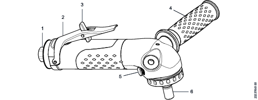
Main Components and Functions
Position | Part | Function |
|---|---|---|
1 | Air inlet | For connection to compressed air through a whip hose. |
2 | Throttle lever | Starts and stops the tool. |
3 | Security mechanism | A two-step function for a safe start and stop of the tool. Press the release arm forward to release the throttle lever |
4 | Support handle | Adjustable for a flexible working position for left or right handed operator. |
5 | Spindle locking button | Locking the spindle to facilitate fastening of the wheel. |
6 | Spindle | For fastening of the wheel. |
Technical Product Data
Technical Product Data can be found on either ServAid, or the Atlas Copco website.
Please visit: https://servaid.atlascopco.com or www.atlascopco.com.
Service Overview
Overhaul
The tool should be examined regularly at six-month intervals. If it is in heavy duty service or not running properly it should be taken out of service more often.
To increase life length of gears, change grease and replace bearings and sealings more often.
After a maximum of 1000 hours the angle gear grease shall be changed. If the grease are not changed in time other angle gear and motor parts might get damaged.
For correct lubrication properties use Rhenus LKR03, a semifluid type of grease. The required amount of grease is maximum 11 cm³.
The strainer at the air inlet should be cleaned frequently to prevent clogging and decreased capacity.
Replacement of Vanes
Replace the vanes in the motor when a power drop of the tool is experienced. If the vanes are not replaced in time other motor parts may be damaged. For increased life length of the vanes use an oil lubricator to dose oil into the air inlet.
General Service and Maintenance Safety
Do not dismantle the tool.
The service must only be done by authorized workshops or qualified service technicians.
Service Recommendations
Preventive maintenance is recommended at regular intervals. See the detailed information on preventive maintenance. If the product is not working properly, take it out of service and inspect it.
If no detailed information about preventive maintenance is included, follow these general guidelines:
Clean appropriate parts accurately
Replace any defective or worn parts
Installation
Installation Requirements
Air Quality
For optimum performance and maximum product life we recommend the use of compressed air with a maximum dew point of +10°C (50°F). We also recommend to install an Atlas Copco refrigeration type air dryer.
Use a separate air filter which removes solid particles larger than 30 microns and more than 90% of liquid water. Install the filter as close as possible to the product and prior to any other air preparation units to avoid pressure drop.
For impulse/impact tools make sure to use lubricators adjusted for these tools. Regular lubricators will add too much oil and therefore decrease the tool performance due to too much oil in the motor.
Make sure that the hose and couplings are clean and free from dust before connecting to the tool.
Both lubricated and lubrication free products will benefit from a small quantity of oil supplied from a lubricator.
Air Lubrication Guide
Brand | Air lubrication |
|---|---|
Atlas Copco | Optimizer (1 liter) 9090 0000 04 |
Q8 | Chopin 46 |
Shell | Shell Air Tool Oil S2 A 320 |
Compressed Air Connection
For correct air pressure and hose size, see the Technical Product Data on - https://servaid.atlascopco.com or www.atlascopco.com.
Make sure that the hose and couplings are clean and free from dust before connecting to the tool.
Installation Instructions
Visual Inspection - Tools and Accessories
Inspect the tool and its parts visually before use.
The parts in the list below may vary depending on model.
Wheel guard or Backing pad
Adapters, nuts or flange washers
Support handle
Throttle lever and security mechanism
Autobalancer
Spindle
Look for any damage, grease or oil leakage that can compromise the safety of the tool.
Visual Inspection - Air Installation
Inspect the air installation visually from the supply point to the tool before use.
Hose
Couplings
System pressure
Air filter
Look for any damage that can compromise the safety of the tool.
Installation Overview
Legend to page 2
-
Recommended torque
-
Hose length
-
Hose diameter
-
Max working air pressure
-
Max free speed
-
Recommended torque
-
Recommended torque
-
Spindle thread
Operation
Ergonomic Guidelines
Consider your workstation as you read through this list of general ergonomic guidelines to identify areas for improvement in posture, component placement, or work environment.
Take frequent breaks and change work positions frequently.
Adapt the workstation area to your needs and the work task.
Adjust for a convenient reach range by determining where parts and tools need to be located to avoid static load.
Use workstation equipment such as tables and chairs appropriate for the work task.
Avoid work positions above shoulder level or with static holding during assembly operations.
When working above shoulder level, reduce the load on the static muscles by lowering the weight of the tool, using for example torque arms, hose reels or weight balancers. You can also reduce the load on the static muscles by holding the tool close to the body.
Take frequent breaks.
Avoid extreme arm or wrist postures, particularly during operations requiring a degree of force.
Adjust for a convenient field of vision that requires minimal eye and head movements.
Use appropriate lighting for the work task.
Select the appropriate tool for the work task.
In noisy environments, use ear protection equipment.
Use high-quality inserted tools and consumables to minimize exposure to excessive levels of vibration.
Minimize exposure to reaction forces.
When cutting:
A cut-off wheel can get stuck if the cut-off wheel is bent or not guided properly. Use the correct flange for the cut-off wheel and avoid bending the cut-off wheel during operation.
When drilling:
The drill might stall when the drill bit breaks through. Use support handles if the stall torque is high. The safety standard ISO11148 part 3 recommends using a device to absorb a reaction torque above 10 Nm for pistol grip tools and 4 Nm for straight tools.
When using direct-driven screwdrivers or nutrunners:
Reaction forces depend on the tool settings and joint characteristics. Strength and posture determine the amount of reaction force that an operator can tolerate. Adapt the torque setting to the operator's strength and posture and use a torque arm or reaction bar if the torque is too high.
In dusty environments, use a dust extraction system or wear a mouth protection mask.
Configuration Instructions
Wheel Configuration Options
The table below shows the configuration option for a pad with applicable attachment parts.

1 | Washers | 3 | Nut locking the pad and abrasive |
2 | Pad | 4 | Locking kit |
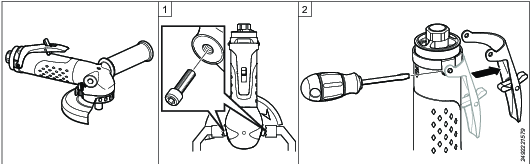
Lever Assembly Options
The lever can be turned from the top side to the underside of the tool.
Remove the support handle and attach two screws in the holes of the angle head.
Hold the tool by the screws using a vice.
Remove the lever using a slotted screwdriver.
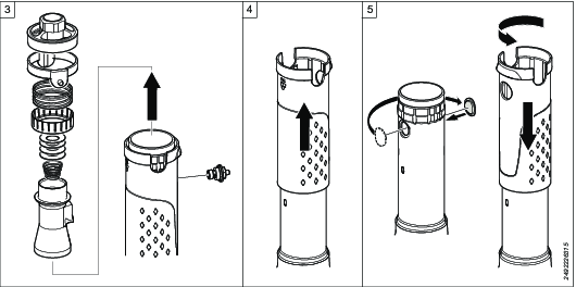
Remove the trigger pin with bushing using a 10 mm socket.
Remove the adapter using a 21 mm socket.
Remove the inlet/outlet parts.
Remove the insulation sleeve.
Move the cover to the opposite side of the casing
Put the insulation sleeve back in position and turn it to attach it to the casing.
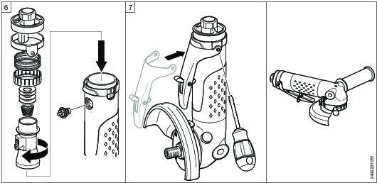
Assemble the inlet/outlet parts.
Make sure the inlet is positioned correctly relative to the trigger pin bushing.
Apply Loctite to the bushing threads.
Attach the bushing loosely by hand.
Apply Loctite to the adapter threads.
Tighten the adapter using a 21 mm socket and torque wrench.
Tighten the trigger pin bushing using a 10 mm socket and a torque wrench.
Attach the lever in the opposite position.
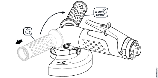
Fitting of Support Handle
The support handle can be attached to any side of the tool.
Remove the support handle by turning it counterclockwise.
Attach the support handle to the opposite side.
Tighten the handle clockwise to the recommended torque.
Operating Instructions
Free Speed Check
Do a daily free speed check with a tachometer. Always do a free speed check of the tool after service.
This check should be done with the sanding equipment detached.
The free speed must not be more than the rated speed marked on the tool.
Operating the Tool
Connect the tool to the air supply (if not already connected).
Point the air exhaust away from the operator.
Push the security mechanism to release the throttle lever.
Push down the throttle lever to start the sander.
Replace the throttle lever if it is not working properly.
Service
Maintenance Instructions
General Service and Maintenance Safety
Do not dismantle the tool.
The service must only be done by authorized workshops or qualified service technicians.
Service Recommendations
Preventive maintenance is recommended at regular intervals. See the detailed information on preventive maintenance. If the product is not working properly, take it out of service and inspect it.
If no detailed information about preventive maintenance is included, follow these general guidelines:
Clean appropriate parts accurately
Replace any defective or worn parts
Overhaul
The tool should be examined regularly at six-month intervals. If it is in heavy duty service or not running properly it should be taken out of service more often.
To increase life length of gears, change grease and replace bearings and sealings more often.
After a maximum of 1000 hours the angle gear grease shall be changed. If the grease are not changed in time other angle gear and motor parts might get damaged.
For correct lubrication properties use Rhenus LKR03, a semifluid type of grease. The required amount of grease is maximum 11 cm³.
The strainer at the air inlet should be cleaned frequently to prevent clogging and decreased capacity.
Replacement of Vanes
Replace the vanes in the motor when a power drop of the tool is experienced. If the vanes are not replaced in time other motor parts may be damaged. For increased life length of the vanes use an oil lubricator to dose oil into the air inlet.
Lubrication Instructions
Rust Protection and Cleaning
Water in the compressed air can cause rust. To prevent rust we strongly recommend to install an air dryer.
Water and particles can cause sticking of vanes and valves. This can be prevented by installing an air filter close to the product to avoid pressure drop.
Before longer standstills always protect your tool by adding a few drops of oil into the air inlet. Run the tool for 5–10 seconds and absorb any access oil at the air outlet in a cloth.
Lubrication Guide
Grease for general purpose | |
|---|---|
BP | Energrease LS-EP2 |
Castrol | OBEEn UF 1 |
Esso | Beacon EP2 |
Q8 | Rembrandt EP2 |
Mobil | Mobilegrease XHP 222 NLG2 |
Klüber Lub. | Klübersynth UH 1 14-151 |
Texaco | Multifak EP2 |
Molykote | BR2 Plus |
Grease for angle gears | |
|---|---|
Rhenus | LKR03 |
Troubleshooting
Troubleshooting
The table below shows the most common troubleshooting procedures. Note that some actions must only be done by authorized workshops or qualified service technicians.
|
Problem |
Reason |
Action |
|---|---|---|
|
Tool does not start |
No air flow to the tool |
Do a check of air connection and compressor |
|
Rotor in dead position |
Disconnect air supply and then turn spindle quickly | |
|
Air filter in tool air inlet blocked |
Clean air filter carefully | |
|
Throttle valve broken |
* | |
|
Motor jammed |
* | |
|
Inconsistent idling speed |
Unstable air pressure |
Do a check of air pressure regulator |
|
Resonance from exhaust |
Start tool rapidly and slowly until noise disappear | |
|
Worn governor |
* | |
|
Low power |
Low air pressure |
Do a check of air pressure |
|
Too long length or too small inner diameter of air supply hoses and pipes |
Do a check of air hoses and air pipes | |
|
Too small inner diameter of air connections |
Do a check of air connections | |
|
Blocked air supply filters |
Clean or replace filters | |
|
Air filter in tool air inlet blocked |
Clean air filter carefully | |
|
Too humid air (high dew point) |
Do a check of the compressor | |
|
Worn throttle valve |
* | |
|
Worn governor |
* | |
|
Worn vanes |
* | |
|
Too hot angle gear |
Too much or too little grease in gear box |
Do a check of grease level (to little grease may cause premature wear) |
|
Blocked air relief passage |
* | |
|
Damaged seals |
* | |
|
Damaged needle bearing |
* | |
|
Damaged spindle bearing |
* | |
|
Damaged gear wheels |
* | |
|
Tool too cold by exhaust |
Because of pressure drop of inlet air exhaust air gets cold |
Assemble exhaust hose |
|
Vanes wear fast |
High friction in motor |
Add oil into inlet air to increase life length of vanes |
|
Dirty air might wear vanes |
Do a check of filters in tool air inlet and in air supply | |
|
Gear wear fast |
Too little grease in angle gear |
Refill correct amount of grease regularly. |
|
Loose oil plug and spindle lock |
Tighten oil plug or spindle lock | |
|
Worn or damaged seals |
* | |
|
Damaged o-rings |
* | |
|
Damaged bearings |
* | |
|
Grease leakage |
Loose oil plug and spindle lock |
Tighten oil plug or spindle lock |
|
Worn or damaged seals |
* | |
|
Damaged o-rings |
* | |
|
Damaged bearings |
* | |
|
Too much grease in gear housing |
Do a check of that angle gear has correct amount of grease | |
|
Tool starts unexpectedly |
Valve pin jammed in start position |
Replace pin and bushing |
|
Damaged security meachanism |
Replace lever | |
|
Damaged throttle valve |
* | |
|
Vibrations |
Worn or damaged grinding wheel |
Replace wheel |
|
Autobalancer not working properly |
Replace autobalancer | |
|
Damaged spindle |
* | |
|
Worn or damaged flange washers |
Replace flange washers | |
|
Too high idle speed |
Governor |
* |
|
Too high air pressure |
Do a check of air pressure | |
|
Abnormal or high sound |
Resonance from exhaust |
Restart tool rapidly and slowly until noise dissapear |
|
Exhaust hose is missing |
Assemble exhaust hose | |
|
Too little grease in gear housing |
* | |
|
Damaged gear |
* | |
|
Damaged spindle |
* | |
|
Bad noise from gears |
* | |
|
Worn bearings |
* |
* This service must only be done by authorized workshop or qualified service technician.
Recycling
Environmental Regulations
When a product has served its purpose it has to be recycled properly. Dismantle the product and recycle the components in accordance with local legislation.
Batteries shall be taken care of by your national battery recovery organization.
Recycling Information
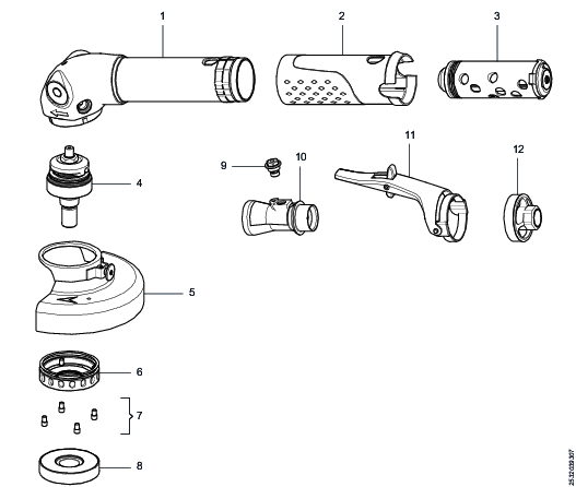
Position | Part | Recycle as |
|---|---|---|
1 | Housing | Metal, Aluminium |
2 | Insulation sleeve | Plastics, Other, TPU |
3 | Vane motor | Metal, Steel* |
4 | Spindle complete | Metal, Steel |
5 | Wheel guard | Metal, Steel |
6 | End cover | Metal, Steel |
7 | Screws | Metal, Steel |
8 | Autobalancer | Metal, Steel |
9 | Bushing | Metal, Brass |
10 | Inlet | Metal, Steel |
11 | Lever complete | Metal, Steel |
12 | Adapter | Metal, Steel |
*The vanes in the product contains PTFE, the normal health and safety recommendations concerning PTFE must be observed.