Aerospace HAD
Product Information
General Information
Safety Signal Words
The safety signal words Danger, Warning, Caution, and Notice have the following meanings:
DANGER | DANGER indicates a hazardous situation which, if not avoided, will result in death or serious injury. |
WARNING | WARNING indicates a hazardous situation which, if not avoided, could result in death or serious injury. |
CAUTION | CAUTION, used with the safety alert symbol, indicates a hazardous situation which, if not avoided, could result in minor or moderate injury. |
NOTICE | NOTICE is used to address practices not related to personal injury. |
Country of Origin
For the Country of Origin, please refer to the information on the product label.
Overview
System Description
The Hold and Drive (HAD) system is used for tightening and loosening of nuts.
The tightening operation is controlled by a separate drive unit to which the system is fitted.
The modular structure of the system allows for a wide range of configurations available for different HAD applications and sizes.
System Components
The HAD system is made up of the following components:
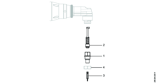
Position | Component | Function |
|---|---|---|
1 | HAD socket | Different socket sizes & lengths are available to fit all types of aerospace applications. |
2 | HAD system | Holds the bit and are available in different lengths to match the socket. |
3 | Bit | Replaceable bit available in different sizes to hold the fastener during tightening. |
4 | Locking nut | Nut for attaching the HAD socket to the angle head. |
Installation
Installation Instructions
Functional Test
Perform a functional test before the first tightening operation, and after any performed maintenance activities.
Manually rotate the output gear wheel. It must rotate smoothly.
Push the bit upwards, it must move easily.
Lubricate the system.
Assembling Instructions
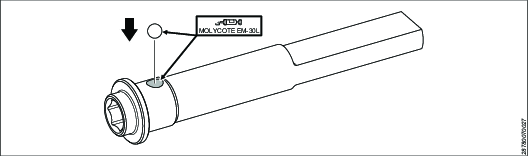
Add a small amount of grease (Molykote EM-30L) and place the ball into the tapered hole on the side on the side bit holder.
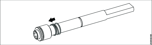
Place the release ring on the bit holder by sliding it on from the top.
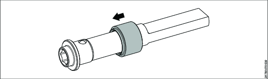
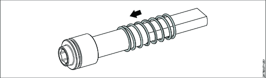
Place the spring on the bit holder by sliding it on from the top.
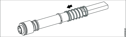
 If two springs are included
Place the short spring on the bit holder by sliding it on from the top.
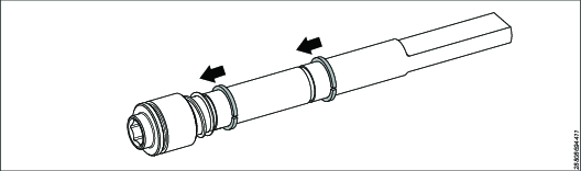
Place the locking rings in the grooves on the bit holder.
Place the long spring on the bit holder by sliding it on from the top.
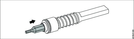
Add the bit by lifting the release ring, pushing in the bit and releasing the ring.
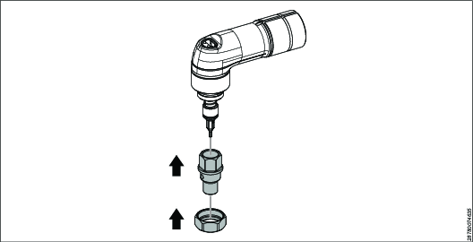
Remove the locking nut from the angle head

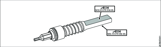
Brush grease (Molykote EM-30L) on the two flat surfaces on the bit holder.
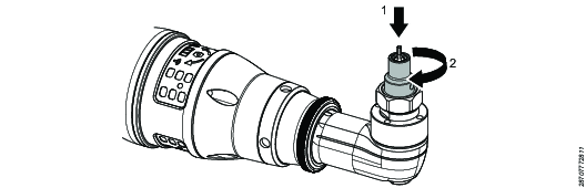
Insert the HAD system, place the top washer on the top of the bit holder and secure it with the M2 screw.

Insert the HAD socket and secure it with the locking nut from the angle head.

Use the flat sides of the bevel gear as a counter hold when tightening.
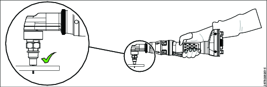
Check that the completed assembly have a small gap between the top washer and the angle head.

Operation
Operating Instructions
Operating the HAD System
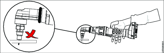
Bending on socket will reduce installed torque for all models.
If the operator puts a bending load on the socket (for example by not holding the tool weight, and letting the tool hang on the screw head) it will reduce the installed torque level. Even though the tool measures and reports a correct torque, the joint will not be properly tightened. This effect is more sensitive at low target torques.
Service
Maintenance Instructions
Service Instructions and Intervals
For information about service instructions and intervals, refer to the Product Instructions for the driving tool.
Changing a HAD System Socket Bit
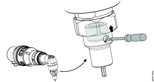
Lift the release ring upwards using a small screwdriver placed in the holes of the socket.
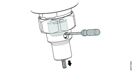
While holding the release ring in the upper position pull the bit downwards to remove the bit.
Recycling
Environmental Regulations
When a product has served its purpose it has to be recycled properly. Dismantle the product and recycle the components in accordance with local legislation.
Batteries shall be taken care of by your national battery recovery organization.