ITB-P31-12-i06
Battery-Powered Nutrunner
Product Information
General Information
Power Tool Information
Safety Signal Words
The safety signal words Danger, Warning, Caution, and Notice have the following meanings:
DANGER | DANGER indicates a hazardous situation which, if not avoided, will result in death or serious injury. |
WARNING | WARNING indicates a hazardous situation which, if not avoided, could result in death or serious injury. |
CAUTION | CAUTION, used with the safety alert symbol, indicates a hazardous situation which, if not avoided, could result in minor or moderate injury. |
NOTICE | NOTICE is used to address practices not related to personal injury. |
Warranty
Product warranty will expire 12+1 months after dispatch from Atlas Copco's Distribution Center.
Normal wear and tear on parts is not included within the warranty.
Normal wear and tear is that which requires a part change or other adjustment/overhaul during standard tools maintenance typical for that period (expressed in time, operation hours or otherwise).
The product warranty relies on the correct use, maintenance, and repair of the tool and its component parts.
Damage to parts that occurs as a result of inadequate maintenance or performed by parties other than Atlas Copco or their Certified Service Partners during the warranty period is not covered by the warranty.
To avoid damage or destruction of tool parts, service the tool according to the recommended maintenance schedules and follow the correct instructions.
Warranty repairs are only performed in Atlas Copco workshops or by Certified Service Partners.
Atlas Copco offers extended warranty and state of the art preventive maintenance through its ToolCover contracts. For further information contact your local Service representative.
For electrical motors:
Warranty will only apply when the electric motor has not been opened.
Website
Information concerning our Products, Accessories, Spare Parts and Published Matters can be found on the Atlas Copco website.
Please visit: www.atlascopco.com.
ServAid
ServAid is a portal that is continuously updated and contains Technical Information, such as:
Regulatory and Safety Information
Technical Data
Installation, Operation and Service Instructions
Spare Parts Lists
Accessories
Dimensional Drawings
Please visit: https://servaid.atlascopco.com.
For further Technical Information, please contact your local Atlas Copco representative.
Safety Data Sheets MSDS/SDS
The Safety Data Sheets describe the chemical products sold by Atlas Copco.
Please consult the Atlas Copco website for more information www.atlascopco.com/sds.
Product Safety Video for Nutrunners
Learn more about safety features on Atlas Copco nutrunners and what measures the operator has to take for a safe operation. Click the link or scan the QR code below to view the video:
https://www.youtube.com/watch?v=FAh6yttvUpw

Country of Origin
For the Country of Origin, please refer to the information on the product label.
Dimensional Drawings
Dimensional Drawings can be found either in the Dimensional Drawings Archive, or on ServAid.
Please visit: http://webbox.atlascopco.com/webbox/dimdrw or https://servaid.atlascopco.com.
Overview
General Description
Pistol Cordless Nutrunner Tensor ITB-P takes productivity, assembly quality and user experience to the next level. ITB-P offers value-add includes TrueAngle angle compensation, faster tightening speeds, improved wireless signal strength and multiple configurable operator feedback via colored front LED, vibrator and embedded display. ITB-P is part of the Tensor IxB Family, with an integrated controller allowing direct integration with station accessories and production system without the need of an intermediate physical controller box.
System Functionality
The tool comprises an embedded controller for configurations of tightening programs, batches and other tool functionality, such as input and output signals.
By connecting the tool to a PC via USB, or by setting up a wireless connection to the factory network, the embedded controller can be accessed through the IxB Software web user interface.
Tool Key
The IxB tool naming format can be used to describe functions and features of the tool. Below is an example tool name with corresponding tool key.

Position | Description | Key |
|---|---|---|
1 | Platform | I = IxB (integrated controller) |
2 | Technology | P = Pulse T = Transducer |
3 | Powering | B = Battery |
4 | Tool shape | A = Angle P = Pistol S = Straight |
5 | Motor size | |
6 | Tool generation | |
7 | Max torque in Nm | |
8 | Output drive | I = Female hex HAD = Hold and Drive |
9 | Drive size | 06 = 1/4" 10 = 3/8" 13 = 1/2" |
10 | Accessories | HMI = EHMI |
11 | Accuracy | H = High torque accuracy |
Product Power Source
This product can be used with either a battery, or with an electrical power cable in combination with a power supply unit.
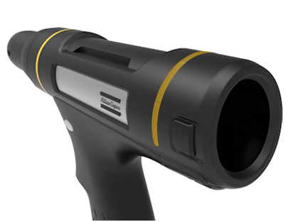
Tool Functionality
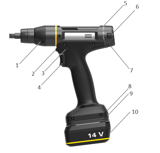
Position | Description |
|---|---|
1 | Front light |
2 | Function button |
3 | Reverse button |
4 | Tool trigger |
5 | LED ring |
6 | Display (RHMI) |
7 | Display buttons |
8 | IAM (SD card) |
9 | USB port |
10 | Battery |
Ambient Temperature
For best battery performance and life time, keep battery within temperature intervals.
Operating temperature, charge | +5 to +40 °C |
Operating temperature, discharge | 0 to +40 °C |
Transportation temperature | −20 to +40 °C |
Storage temperature | +10 to +25 °C |
Do not place battery in direct sunlight.
Technical Product Data
Technical Product Data can be found on either ServAid, or the Atlas Copco website.
Please visit: https://servaid.atlascopco.com or www.atlascopco.com.
Accessories
Accessory Information
Visit the tool's product page on ServAid for information about compatible accessories.
Basic RHMI
The Basic RHMI (Round Human Machine Interface) is located on the back of the tool and comprises of four push buttons and a graphical display.
The display serves as a tool-integrated interface for the operator, showing a subset of the IxB Software web user interface.
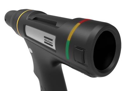
LED Indicators
The LED ring of the tool is equipped with the following indicators:
LED indicator | Main indication |
|---|---|
Red status LEDs | Tightening result, NOK |
Green status LEDs | Tightening result, OK |
Yellow status LEDs | Can be configured in the IxB Software to indicate different events |
Advanced RHMI
The advanced RHMI functions are only available with a licence.
The advanced function must be activated in the IxB Software web user interface.
RHMI Module Description
The RHMI (Round Human Machine Interface) module provides a tool-mounted interface for the operator, showing a subset of the IxB Software web user interface. It can be used to choose tightening programs and batch sequences, as well as display tightening results and progression within batch sequences.
The RHMI user interface consists of four push buttons and a graphical display. The buttons are used to navigate through the menus and to confirm selections.
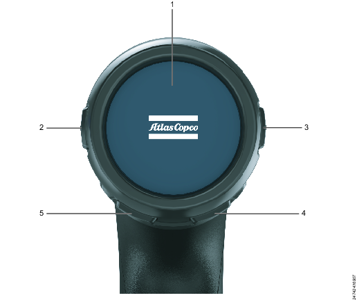
Position | Name | Description |
|---|---|---|
1 | Display | Screen displaying information to the user. |
2 | Left or up button | Physical button for moving on-screen selection left or up. |
3 | Right or down button | Physical button for moving on-screen selection right or down. |
4 | Select button | Physical button for confirming an on-screen selection. |
5 | Back button | Physical button for moving on-screen selection down, as well as to navigate to the main menu (by pressing and holding for three seconds). |
Main Menu
The main menu of the RHMI contains the following options:
Menu Item | Description |
|---|---|
| The Tightenings menu shows a list of all the tightening programs available in the tool. |
| The Batch menu shows a list of all the batch sequences available in the tool. |
| The Information menu provides information about the tool and software. |
| The Network menu provides information on the factory network that the RHMI is connected to. |
| The Results menu shows the tightening results. |


Indicator Bar
The indicator bar is presented at the top of all menus. The icons in the indicator bar provides information on the elements listed below.
Icon | Description |
|---|---|
| The wireless connection icon indicates the signal strength of the tool's factory network connection. When no connection is established, the icon is crossed out. |
| The reverse ring icon indicates the position of the reverse ring on the tool, that is, the direction of rotation when the tool trigger is pushed. If the tool is disabled, the icon is crossed out. |
| The battery icon Indicates the charge status of the battery attached to the tool. |


The battery charge levels are listed below.
Battery Icon | Charge Level |
|---|---|
 | Full |
 | Medium |
| Low |
| Critically low |
| Tool is running on internal backup battery |
| No information available |


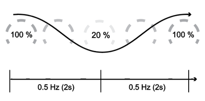
Front Light and LED Ring Behavior
The standard flash patterns of the LED ring is shown below. To configure the LED ring behavior, refer to IxB Software User Guide.
Starting Up
Part | Active | Color | Pattern | Duration |
|---|---|---|---|---|
LED ring | Yes | White | Breathing | Until process completed |
Front light | No | |||
Buzzer | No |
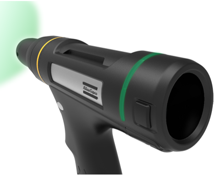
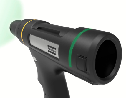
OK Tightening

Part | Active | Color | Pattern | Duration |
|---|---|---|---|---|
LED ring | Yes | Green | Steady | Until next tightening / customizable |
Front light | Yes | Green | Steady | Until next tightening / customizable |
Buzzer | No |
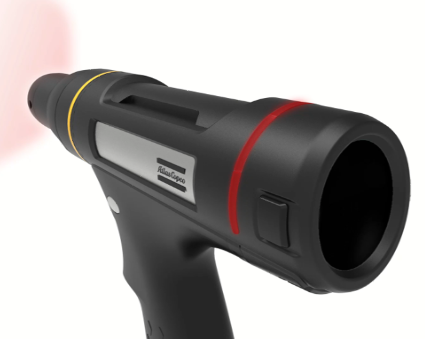
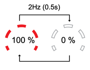
NOK Tightening
Part | Active | Color | Pattern | Duration |
|---|---|---|---|---|
LED ring | Yes | Red | Blinking loop | Until next tightening / customizable |
Front light | Yes | Red | Blinking loop | Until next tightening / customizable |
Buzzer | No |
Low Value

Part | Active | Color | Pattern | Duration |
|---|---|---|---|---|
LED ring | Yes | Yellow | Steady | Until next tightening / customizable |
Front light | No |
| ||
Buzzer | No |
Two Color Setup
For example: NOK / Low Value result.
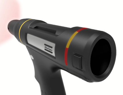
Part | Active | Color | Pattern | Duration |
|---|---|---|---|---|
LED ring | Yes | Red + Yellow | Steady | Until next tightening / customizable |
Front light | Yes | Red | Blinking loop | Until next tightening / customizable |
Buzzer | No |
Two Color Setup (Signals)
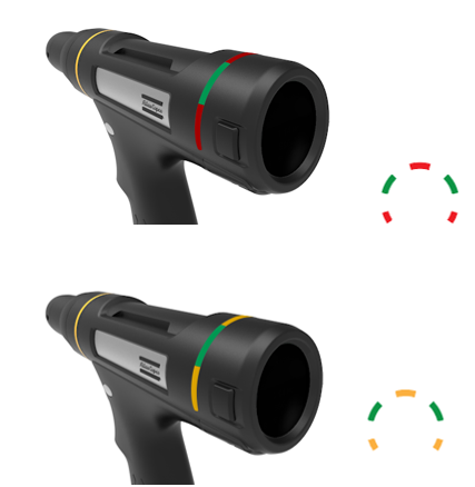
Part | Active | Color | Pattern | Duration |
|---|---|---|---|---|
LED ring | Yes | Red + Green | Steady | Until next tightening / customizable |
Front light | No | |||
Buzzer | No |
Part | Active | Color | Pattern | Duration |
|---|---|---|---|---|
LED ring | Yes | Yellow + Green | Steady | Until next tightening / customizable |
Front light | No | |||
Buzzer | No |
Three Color Setup

Part | Active | Color | Pattern | Duration |
|---|---|---|---|---|
LED ring | Yes | Red + Yellow + Green | Steady | Until next tightening / customizable |
Front light | No | |||
Buzzer | No |
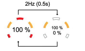
Rescue Mode
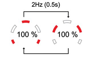
Part | Active | Color | Pattern | Duration |
|---|---|---|---|---|
LED ring | Yes | Red | Alternate blink | Until next tightening / customizable |
Front light | No | |||
Buzzer | No |
Time Off
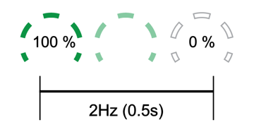
Part | Active | Color | Pattern | Duration |
|---|---|---|---|---|
LED ring | Yes | Red or Green depending on case | Fade out | 0.5 sec |
Front light | Yes | When OK or NOK | Fade out | 0.5 sec |
Buzzer | No |
Installation
Installation Instructions
Connecting to the IxB Software Web User Interface
Attach the power source to the tool. The red and green LED indicators, together with the direction LED indicators are flashing, showing that the tool is starting up. Wait until the battery LED, and one of the direction LED indicators are lit. The tool is now ready to operate.
Remove the cover of the tool's USB port.
Connect the tool to the USB port of the PC. Open a web browser and type in the address of the IxB Software user interface: 169.254.1.1.
Battery LED do not light when PSU is connected.
Product Essentials Tutorials
https://www.youtube.com/watch?v=ffQHjRwbIgw
Installing Accessories
For information on how to mount accessories on the tool, refer to Mounting ITB-P Accessories.
Attaching the Electrical Power Cable
To attach the electrical power cable, see Product Instructions for Power Supply Unit 950.
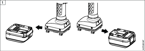
Attaching and Removing the Battery
Attach the battery to the tool and make sure that it is fastened correctly. The battery can be attached pointing forward or backward to get the best accessibility and balance.
To remove the battery, press the button on the battery and push it out.
Initial Configuration
Software Installation and Upgrade
For information about software installation and upgrade, refer to IxB Software User Guide.
Tool Configuration
For information about establishing a wireless connection, installing licenses, configuring and assigning tightening programs, refer to IxB Software User Guide.
The link refers to the latest version of the software. User guides describing earlier versions of the software are available on ServAid.
Operation
Ergonomic Guidelines
Consider your workstation as you read through this list of general ergonomic guidelines to identify areas for improvement in posture, component placement, or work environment.
Take frequent breaks and change work positions frequently.
Adapt the workstation area to your needs and the work task.
Adjust for a convenient reach range by determining where parts and tools need to be located to avoid static load.
Use workstation equipment such as tables and chairs appropriate for the work task.
Avoid work positions above shoulder level or with static holding during assembly operations.
When working above shoulder level, reduce the load on the static muscles by lowering the weight of the tool, using for example torque arms, hose reels or weight balancers. You can also reduce the load on the static muscles by holding the tool close to the body.
Take frequent breaks.
Avoid extreme arm or wrist postures, particularly during operations requiring a degree of force.
Adjust for a convenient field of vision that requires minimal eye and head movements.
Use appropriate lighting for the work task.
Select the appropriate tool for the work task.
In noisy environments, use ear protection equipment.
Use high-quality inserted tools and consumables to minimize exposure to excessive levels of vibration.
Minimize exposure to reaction forces.
When cutting:
A cut-off wheel can get stuck if the cut-off wheel is bent or not guided properly. Use the correct flange for the cut-off wheel and avoid bending the cut-off wheel during operation.
When drilling:
The drill might stall when the drill bit breaks through. Use support handles if the stall torque is high. The safety standard ISO11148 part 3 recommends using a device to absorb a reaction torque above 10 Nm for pistol grip tools and 4 Nm for straight tools.
When using direct-driven screwdrivers or nutrunners:
Reaction forces depend on the tool settings and joint characteristics. Strength and posture determine the amount of reaction force that an operator can tolerate. Adapt the torque setting to the operator's strength and posture and use a torque arm or reaction bar if the torque is too high.
In dusty environments, use a dust extraction system or wear a mouth protection mask.
Operating Instructions
Tool Calibration
For information on calibration of this tool, refer to IxB Software User Guide.
The link refers to the latest version of the software. User guides describing earlier versions of the software are available on ServAid.
RHMI Operations
Enabling or Disabling the RHMI Select Button
The RHMI Select button can be enabled or disabled in the IxB Software web user interface, refer to IxB Software User Guide.
Events
Events in the system will generate event dialog boxes in the RHMI display, as well as in the IxB Software web user interface. To acknowledge events in the RHMI, press the Select button once.
Some events are not possible to acknowledge. They will show for three seconds before automatically disappearing from the display.
Tightenings
The RHMI can be used to select the tightening program for the tool. The selection of a tightening program made on the RHMI overrides whatever task was set for the tool in the IxB Software web user interface. Only tightening programs stored in the IxB Software of the tool can be selected from the RHMI.
Selecting a Tightening Program
If not in the main menu, press and hold the Select button until the main menu shows.
Press the Select button to open the Tightening menu.
Use the Up- and Down buttons to select a tightening program from the list. The number of the currently selected tightening program is marked white.
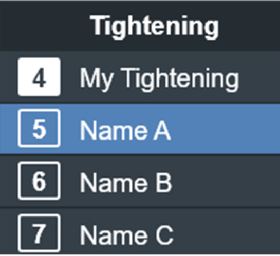
Press the Select button to confirm.
Reading a Tightening Result
The tightening result is presented graphically, indicating either an OK or NOK tightening (green for OK, red for NOK). The angle and torque results are displayed on the screen.

Batch
Batch sequences are used when operators need to perform a series of tightenings in a single job, and can be restricted to only follow a specific order in which the tightenings are performed. Batch sequences consist of one or more batches, and each batch consists of one or more tightenings.
The RHMI can be used to select the batch sequence for the tool. The selection of a batch sequence made on the RHMI overrides whatever task was set for the tool in the IxB Software web user interface.
Selecting a Batch Sequence
If not in the main menu, press and hold the Select button until the main menu shows.
Use the Down button to cycle through the main menu items to the Batch menu.
Press the Select button to open the Batch menu.
Use the Up- and Down buttons to select the batch sequence from the list.
Press the Select button to confirm.
Viewing Tool and Software Information
If not in the main menu, press and hold the Select button until the main menu shows.
Use the Up- and Down buttons to cycle through the main menu items to the Information menu.
Press the Select button to open the Tool or Software menu.
Use the Up- and Down buttons to view the tool or software information.
The Tool menu provides the following information:
Tool Information | Description |
|---|---|
Model | Tool model designation |
Serial no | Tool serial number |
Product number | Product number for ordering the tool |
Max torque | Tool's maximum torque |
Max speed | Tool's maximum speed |
Gear ratio | Gear ratio of the tool shaft |
Calibration date | Date the tool was last calibrated |
Next calibration date | Date when the tool should be calibrated next |
The Software menu provides the following information:
Software Information | Description |
|---|---|
Software version | Software version installed and date of installation |
Viewing Network Information
If not in the main menu, press and hold the Select button until the main menu shows.
Use the Up- and Down buttons to cycle through the main menu items to the Network menu.
Press the Select button to open the Network menu.
Use the Up- and Down buttons to view the network information.
The Network menu provides the following information about the network that the tool is connected to:
Network Information | Description |
|---|---|
IP address | IP address of the tool |
Gateway | IP address subnet mask |
Subnet mask | Connection gateway |
Mac address | Mac address of the tool |
Connection status | Connection status of the tool |
Tightening
As tightening torque increase the reaction force build up equally. Make sure that the tool is in correct working order and that the controller is correctly programmed. By doing this you avoid unexpected behavior from the tool, which may result in operator injury.
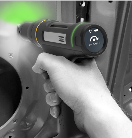
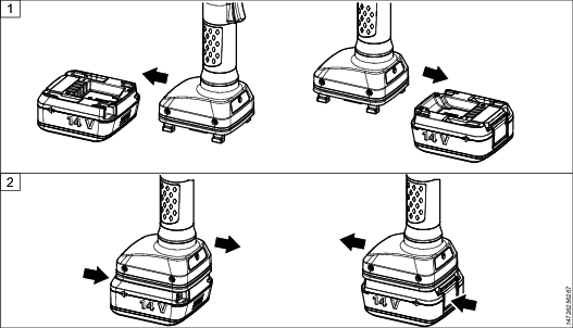
Rotation Direction for the Tightening
Check that the tool is in the correct running direction by pressing the reverse button:
Press in the reverse button on the right hand side of the tool, to set the direction to clockwise (CW).
Press in the reverse button on the left hand side of the tool, to set the direction to counter clockwise (CCW).
Service
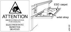
Preventing ESD Problems
The components inside the product and controller are sensitive to electrostatic discharge. To avoid future malfunction, make sure that service and maintenance is carried out in an ESD approved work environment. The figure below shows an example of an appropriate service work station.
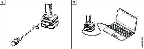
Transferring Configurations with IAM
The Intelligent Application Module (IAM) has the form factor of an SD card. The card contains all the current network configurations and settings.
In case of a tool failure, the card can be transferred to a new tool and all functionality remains the same. When the card is transferred, the new tool will be updated to the software on the card. It is good practice to make sure the new tool is already running the same software version as the old tool, to minimize the risk of data loss.
Note that the saved results associated with the tool will be lost when the card is transferred to another tool. The MAC-address is associated with the card, not with the tool itself. When transferring a card to a new tool, the tool's MAC-address will therefore be updated.
IAM can not be used for anything but storing the tool configuration data and software. Reformatting the card, as well as manipulating the data on the card through other means than IxB Software or ToolsTalk Service 2, will result in an unusable card.
Product Essentials Tutorials
https://www.youtube.com/watch?v=zB0QcQSdsz8
Maintenance Instructions
Overhaul
Have the tool serviced by a qualified repair person using only identical replacement parts. This will ensure that the safety of the tool is maintained. Service must only be carried out by qualified personnel who have been trained for service on IxB tools.
The electric motor is a sealed unit and may under no circumstances be opened by anyone else than Atlas Copco Industrial Technique AB. If it is judged that the electric motor is defect or in need of service, the complete motor unit should be returned to Atlas Copco Industrial Technique AB for exchange. Motors which have been opened by anyone else than Atlas Copco Industrial Technique AB will not be serviced.
Overhaul and preventive maintenance is recommended at regular intervals once per year or after maximum 250.000 tightenings, depending on which occurs sooner. More frequent overhaul may be needed if the machine is used in heavy-duty operations. If the machine is not working properly, it should immediately be taken out of service for inspection.
When dismantling the tool always use the specially designed service tool(s) recommended in the Spare Parts section on ServAid - https://servaid.atlascopco.com.
Service Recommendations
Preventive maintenance is recommended at regular intervals. See the detailed information on preventive maintenance. If the product is not working properly, take it out of service and inspect it.
If no detailed information about preventive maintenance is included, follow these general guidelines:
Clean appropriate parts accurately
Replace any defective or worn parts
Backup Battery Maintenance
The tool includes an internal backup battery. The backup battery is used, for example, to keep the radio communication active during exchange of the main battery. The backup battery gives approximately 20 seconds to exchange the main battery, before the tool shuts down.
Always connect a newly manufactured tool to a main battery and power it up for two hours to charge the backup battery.
When using software versions prior to the versions listed in below table, replace the backup battery at least every 12 months. The replacement procedure must be carried out by a qualified service technician. A replaced backup battery is to be recycled according to the Recycling Instruction.
With software releases according to below table, replace the backup battery every third year. The increased service interval applies to a fresh battery used only together with the software versions in below table. If the backup battery already is close to 12 months old, it is recommended to replace the backup battery when updating to the new software.
TBP/TBP-S | SRB31 | SRB81 | IxB |
Version 2.1.3 or later | Version 1.3.15 or later | Version 1.4.0 or later | Version 3.10.4 or later |
Storage Conditions
The backup battery lifetime is negatively affected by extreme temperatures. Store the tool in an environment with an ambient temperature between 0 - 30 °C. Do not keep spare backup batteries in storage.
If a newly manufactured tool is to be kept in storage, make sure to power it up for at least two hours before putting it in storage.
While in storage, make sure to power on the tool at least every five months to recharge the backup battery. The tool must be powered on for at least two hours each time.
Lubrication Instructions
Lubricant Guide
Part | Lubricant |
|---|---|
Gears | Molycote BR2 Plus |
General purpose | Almagard LE 3751 |
Lubrication
Lubricate according to the Lubrication Guide at each service occasion.
For more information, see Spare Parts section in ServAid - https://servaid.atlascopco.com.
Troubleshooting
Events and Error Codes
For a full list of tool event and error codes, refer to IxB Software User Guide.
Overheated Tool
The tool can handle any normal line jobs that an operator sustains with the proper adjustments.
The tool temperature can be influenced by the following parameters:
short cycle time
torque above rated
too low speed
very high prevailing torque
very soft joints
ambient temperature
Recycling
Environmental Regulations
When a product has served its purpose it has to be recycled properly. Dismantle the product and recycle the components in accordance with local legislation.
Batteries shall be taken care of by your national battery recovery organization.
Recycling Instruction
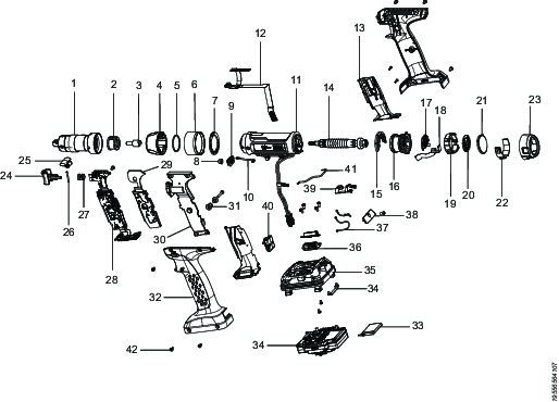
Pos. | Part | Remarks | Recycle as |
|---|---|---|---|
1 | Front gear | Metal, aluminum and steel | |
2 | Transducer | Electronics | |
3 | Intermediate shaft | Metal, steel | |
4 | Front light cap nut | Plastic, other, PA | |
5 | O-ring | 2 pcs | Rubber, PUR |
6 | Spacer | Metal, aluminum | |
7 | Front light board | Electronics | |
8 | Button | Plastic, other, PA | |
9 | Circuit board | Electronics | |
10 | Cable | Electronics | |
11 | Motor frame and stator | Metal, copper, aluminum and steel | |
12 | Motor flex | Electronics | |
13 | Handle support | Left, Right | Plastic, other, PA |
14 | Rotor | Metal, neodymium and steel | |
15 | Light transmitter | 5 pcs | Plastic, other, PA |
16 | Bearing shield | Metal, aluminum | |
17 | RHMI LED flex | Electronics | |
18 | MIPI flex | Electronics | |
19 | Carrier | Plastic, other, PA | |
20 | RHMI board | Electronics | |
21 | RHMI display | Electronics | |
22 | RHMI buttons | Electronics | |
23 | Back cover | Metal, aluminum | |
24 | Trigger | Plastic, other, neodymium | |
25 | Reverse button | Plastic, other, neodymium | |
26 | Pin | Metal, steel | |
27 | Spring | Metal, steel | |
28 | Main board | Electronics | |
29 | Main board support rubber | Rubber, PUR | |
30 | Handle support | Metal, aluminum | |
31 | Screw | 2 pcs | Metal, aluminum |
32 | Handle | Left, Right | Plastic, other, PA |
33 | Backup battery | Battery, Li-ion | |
34 | Power module | Electronics | |
35 | Tool base | Metal, aluminum | |
36 | Antenna board | 2 pcs | Electronics |
37 | Antenna cable | 2 pcs | Electronics |
38 | Lid | Plastic, other, PA | |
39 | Earthing plinth | Metal, steel | |
40 | Connector | Plastic, other, PA | |
41 | Cable | Electronics | |
42 | Screw | 27 pcs | Metal, steel |