5G Connect-S ITB-A
Product Information
General Information
Safety Signal Words
The safety signal words Danger, Warning, Caution, and Notice have the following meanings:
DANGER | DANGER indicates a hazardous situation which, if not avoided, will result in death or serious injury. |
WARNING | WARNING indicates a hazardous situation which, if not avoided, could result in death or serious injury. |
CAUTION | CAUTION, used with the safety alert symbol, indicates a hazardous situation which, if not avoided, could result in minor or moderate injury. |
NOTICE | NOTICE is used to address practices not related to personal injury. |
Website
Information concerning our Products, Accessories, Spare Parts and Published Matters can be found on the Atlas Copco website.
Please visit: www.atlascopco.com.
ServAid
ServAid is a portal that is continuously updated and contains Technical Information, such as:
Regulatory and Safety Information
Technical Data
Installation, Operation and Service Instructions
Spare Parts Lists
Accessories
Dimensional Drawings
Please visit: https://servaid.atlascopco.com.
For further Technical Information, please contact your local Atlas Copco representative.
Country of Origin
For the Country of Origin, please refer to the information on the product label.
Dimensional Drawings
Dimensional Drawings can be found either in the Dimensional Drawings Archive, or on ServAid.
Please visit: http://webbox.atlascopco.com/webbox/dimdrw or https://servaid.atlascopco.com.
Overview
LED Indicators
The 5G Connect-S ITB-A is equipped with two LEDs that indicate different statuses.
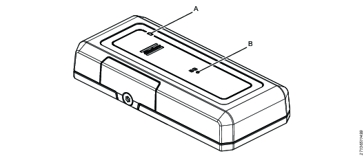
Position | LED | Indications |
|---|---|---|
A | Steady white | Power is on. |
B | Steady blue | Ready to connect.* |
* This is not equal to the tool being connected to the network. Please refer to the tool HMI for the connection status of the tool to the network.
Technical Product Data
Technical Product Data can be found on either ServAid, or the Atlas Copco website.
Please visit: https://servaid.atlascopco.com or www.atlascopco.com.
Installation
Installation Requirements
Prerequisites
The tool, on which the 5G Connect-S ITB-A is to be installed, must have a serial number that begins with at least C. For tools with a serial number that starts with A or B, the motor flex card needs to be replaced before the tool can be used with the 5G Connect-S ITB-A. Please contact the nearest Atlas Copco service center for more information.
Installation Instructions
Installing Accessories
The disassemble of the tool or the accessories must only be performed by qualified maintenance personnel.
Remove the battery from the tool before starting to disassemble.
Required tools:
Adjustable spanner
Screwdriver
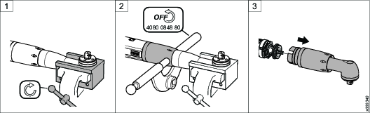
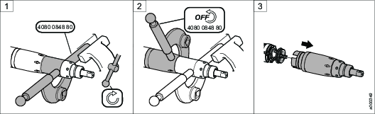
Put the front part in a clamping jaw (choose a suitable size) and fasten the clamping jaw in a vise.
Loosen the front cap nut using an adjustable spanner. Remove the tool from the vise.
Pull out the angle gear carefully from the tool.
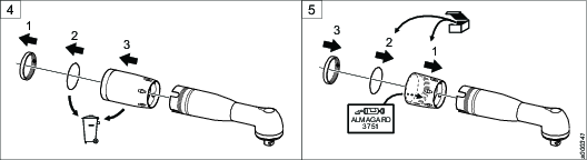
Remove the following parts from the angle gear housing:
The lock ring (keep for later use).
The sealing washer (to be discarded).
The front cap nut (to be discarded).
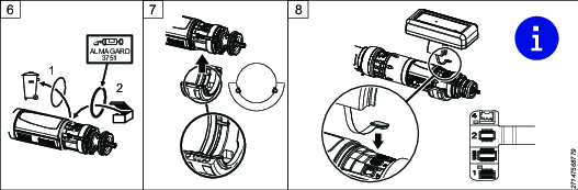
Mount the following parts on the angle gear housing:
New applicable front cap nut. Apply a thin layer of grease on the inside of the cap nut.
New sealing washer.
Lock ring.
Replace the O-ring on the motor housing with an O-ring with the same diameter but thicker. Apply a thin layer of grease on the O-ring and on the lower section of the motor housing.
Place the tool into the half-ring with two pins on the inside. When the half-ring is placed in correct position, the pins will fit into the slots of the motor housing and prevent the half-ring from turning.
Connect the flex cable on the upper half-ring to the USB port on the tool and put the two half-rings together.

The USB connector can be damaged if not connected correctly. The USB connector must be connected so that the flex cable is folded over itself and not twisted.
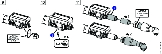
Place an O-ring in the slot at the front of the half-rings. Apply a thin layer of grease on the O-ring.
Tighten the two half-rings with 4 screws using a screwdriver.
Make sure the sealing on the end of the half-rings seals tightly.
Pull out the planetary gear from the gear housing. Push down the planetary gear fully on the shaft.
Make sure the gear wheel is placed in correct position.
Put the gear back in position. Apply a thin layer of grease on the sealing washer.
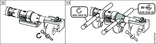
Put the front part in the clamping jaw and fasten the clamping jaw in the vise.
Tighten the front cap nut using adjustable spanners.
Installing the Nano SIM card
Refer to the 5G Connect-S ITB-A User Guide for information on how to install the Nano SIM card.
Initial Configuration
Configuration
Refer to the 5G Connect-S ITB-A User Guide for information on how to configure the software.
Operation
Ergonomic Guidelines
Consider your workstation as you read through this list of general ergonomic guidelines to identify areas for improvement in posture, component placement, or work environment.
Take frequent breaks and change work positions frequently.
Adapt the workstation area to your needs and the work task.
Adjust for a convenient reach range by determining where parts and tools need to be located to avoid static load.
Use workstation equipment such as tables and chairs appropriate for the work task.
Avoid work positions above shoulder level or with static holding during assembly operations.
When working above shoulder level, reduce the load on the static muscles by lowering the weight of the tool, using for example torque arms, hose reels or weight balancers. You can also reduce the load on the static muscles by holding the tool close to the body.
Take frequent breaks.
Avoid extreme arm or wrist postures, particularly during operations requiring a degree of force.
Adjust for a convenient field of vision that requires minimal eye and head movements.
Use appropriate lighting for the work task.
Select the appropriate tool for the work task.
In noisy environments, use ear protection equipment.
Use high-quality inserted tools and consumables to minimize exposure to excessive levels of vibration.
Minimize exposure to reaction forces.
When cutting:
A cut-off wheel can get stuck if the cut-off wheel is bent or not guided properly. Use the correct flange for the cut-off wheel and avoid bending the cut-off wheel during operation.
When drilling:
The drill might stall when the drill bit breaks through. Use support handles if the stall torque is high. The safety standard ISO11148 part 3 recommends using a device to absorb a reaction torque above 10 Nm for pistol grip tools and 4 Nm for straight tools.
When using direct-driven screwdrivers or nutrunners:
Reaction forces depend on the tool settings and joint characteristics. Strength and posture determine the amount of reaction force that an operator can tolerate. Adapt the torque setting to the operator's strength and posture and use a torque arm or reaction bar if the torque is too high.
In dusty environments, use a dust extraction system or wear a mouth protection mask.
Service
Maintenance Instructions
Maintenace of the Hybrid Supercapacitor
If the 5G Connect-S ITB-A is not used for 6 months it needs to be charged.
Loosen the screw and remove the side cover on the 5G Connect-S ITB-A.
Connect the Micro USB port on the 5G Connect-S ITB-A to a suitable electric power supply, using a cable with a Micro USB connector in one end, and a USB connector of your choice in the other end.
Charge for approximately 1.5 minutes.
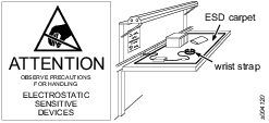
Preventing ESD Problems
The components inside the product are sensitive to electrostatic discharge. To avoid future malfunction, make sure that service and maintenance is carried out in an ESD approved work environment. The figure below shows an example of an appropriate service work station.
Recycling
Environmental Regulations
When a product has served its purpose it has to be recycled properly. Dismantle the product and recycle the components in accordance with local legislation.
Batteries shall be taken care of by your national battery recovery organization.
Recycling Information
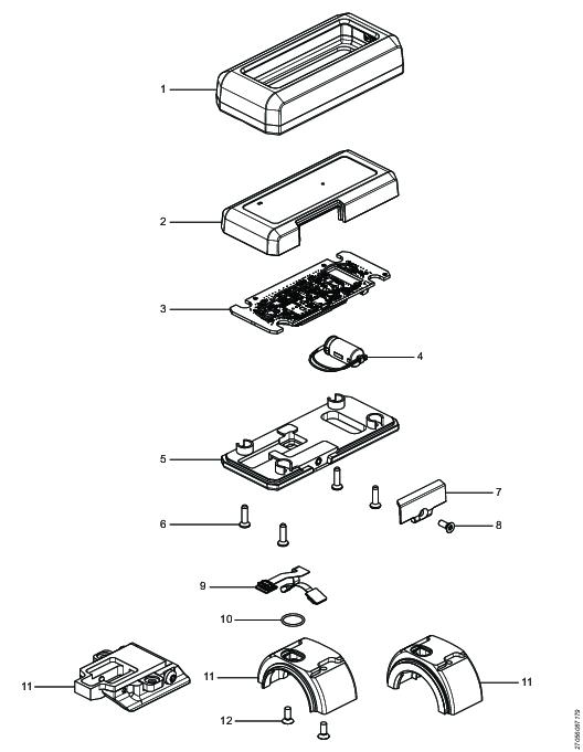
Position | Part | Recycle as |
|---|---|---|
1 | Protective cover | Rubber, PU |
2 | Top cover | Plastic, Other, PA |
3 | PCBA assembly | Electronics |
4 | Capacitor assembly | Electronics |
5 | Bottom plate | Metals, Aluminum |
6 | Hex sock screw | Metals, Steel |
7 | Lid | Plastic, Other, PA |
8 | Hex sock screw | Metals, Steel |
9 | Flex board PCBA | Electronics |
10 | O-ring | Rubber, NBR |
11 | Scanner bracket | Metals, Aluminum |
12 | Hex sock screw | Metals, Steel |