Flex Charger
Charger
Product Information
General Information
Safety Signal Words
The safety signal words Danger, Warning, Caution, and Notice have the following meanings:
DANGER | DANGER indicates a hazardous situation which, if not avoided, will result in death or serious injury. |
WARNING | WARNING indicates a hazardous situation which, if not avoided, could result in death or serious injury. |
CAUTION | CAUTION, used with the safety alert symbol, indicates a hazardous situation which, if not avoided, could result in minor or moderate injury. |
NOTICE | NOTICE is used to address practices not related to personal injury. |
Warranty
Product warranty will expire 12 months after the product is first taken into use, but will in any case expire at the latest 13 months after delivery.
Normal wear and tear on parts is not included within the warranty.
Normal wear and tear is that which requires a part change or other adjustment/overhaul during standard tools maintenance typical for that period (expressed in time, operation hours or otherwise).
The product warranty relies on the correct use, maintenance, and repair of the tool and its component parts.
Damage to parts that occurs as a result of inadequate maintenance or performed by parties other than Atlas Copco or their Certified Service Partners during the warranty period is not covered by the warranty.
To avoid damage or destruction of tool parts, service the tool according to the recommended maintenance schedules and follow the correct instructions.
Warranty repairs are only performed in Atlas Copco workshops or by Certified Service Partners.
Atlas Copco offers extended warranty and state of the art preventive maintenance through its ToolCover contracts. For further information contact your local Service representative.
For electrical motors:
Warranty will only apply when the electric motor has not been opened.
Website
Information concerning our Products, Accessories, Spare Parts and Published Matters can be found on the Atlas Copco website.
Please visit: www.atlascopco.com.
ServAid
ServAid is a portal that is continuously updated and contains Technical Information, such as:
Regulatory and Safety Information
Technical Data
Installation, Operation and Service Instructions
Spare Parts Lists
Accessories
Dimensional Drawings
Please visit: https://servaid.atlascopco.com.
For further Technical Information, please contact your local Atlas Copco representative.
Safety Data Sheets MSDS/SDS
The Safety Data Sheets describe the chemical products sold by Atlas Copco.
Please consult the Atlas Copco website for more information www.atlascopco.com/sds.
Special precautions for charging batteries
Country of Origin
For the Country of Origin, please refer to the information on the product label.
Dimensional Drawings
Dimensional Drawings can be found either in the Dimensional Drawings Archive, or on ServAid.
Please visit: http://webbox.atlascopco.com/webbox/dimdrw or https://servaid.atlascopco.com.
Overview
Flex Charger
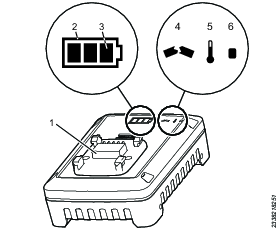
Position | Description |
|---|---|
1 | Battery adapter |
2 | State of health indicator (SOH) |
3 | State of charge indicator (SOC) |
4 | Broken indicator |
5 | Temperature indicator |
6 | Power indicator |
Use
Mains voltage 100 - 240V.
Charging time is approximate 60 minutes, based on an ambient temperature of 25°C.
No other use permitted. For professional use only.
Installation
Installation Requirements
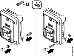
Assemble Flex Charger
There are two different ways to assemble the Flex charger.
Operation
Operating Instructions
Operating the Flex Charger
The Flex Charger is designed for a mains voltage/frequency range of 100V to 240V and 50Hz to 60Hz.
Connect the charger to the mains power. When the charger is connected to the mains supply, the power indicator glows green.
Insert the Li-ion battery into the charging station. Charging starts automatically as soon as the battery is inserted. The charging time depends on the charge state and capacity of the Li-ion battery.
Interconnect Chargers
The Flex charger has built in interconnection. The maximum number of chargers interconnected is limited, depending on the output voltage of the power supply.
Maximum 4 chargers at 100VAC (Japan)
Maximum 5 chargers at 110-120VAC
Maximum 10 chargers at 240VAC
This includes the master charger, that is connected to the alternating current (AC) grid.
Battery Health and Charge Display
When the charger is connected to a battery, the state of health (SOH) and the state of charge (SOC) will glow for 5 seconds before starting the charge pattern.
Battery State of Health
Battery health is shown by the outline of the battery indicator.
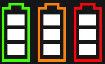
Battery light | Battery health | Remark |
|---|---|---|
Green | Good | Battery is healthy and performing well |
Yellow | Decreased | Battery will eventually need to be replaced |
Red | Low | Replace the battery |
Battery State of Charge
The battery charge is shown by the bars in the battery indicator and shows 5 levels:

Level | Battery bar indicator | Battery status | Remark |
|---|---|---|---|
1 | 3 white | Full charge | |
2 | 2 white | Medium charge | |
3 | 1 white | Low charge | Charge battery, when possible |
4 | 1 red blinking | Nearly empty | Charge battery |
5 | 1 red | Empty and will not work | Charge battery |
Service
Maintenance Instructions
General Service and Maintenance Safety
Do not open the charger. Repairs are only to be performed by authorised service technicians.
Repair Instructions
Changing Adapter on the Charger

Upgrading the Charger Software
Copy the software file to an empty USB memory and make sure the file name is ACTA_FW_.BIN.

If the file name is incorrect, the software upgrade will not be performed.
Disconnect the charger from the power outlet and await the green power LED indicator to turn off (this will take approximately 30 seconds).
Unscrew and remove the battery adapter on top of the charger.
Connect the USB memory to the charger's USB port (positioned on top of the charger).
Connect the charger to the power outlet.
The software will now be automatically upgraded. While the upgrade is in progress the state of health (SOH) LED indicator is flashing white. The upgrade procedure takes a few seconds.
When the upgrade is finished the state of health (SOH) and the state of charge (SOC) LED indicators are lit with a steady white light for a few seconds, and then turns off.
Disconnect the charger from the power outlet and await the green power LED to turn off (this will take approximately 30 seconds).
Disconnect the USB memory.
Reattach the battery adapter and fasten the screws.
Connect the charger to the power outlet. The charger is now ready to operate.
Troubleshooting
Troubleshooting
Charger Errors
Indicator | Description |
|---|---|
 | Recoverable charger error, such as charger overheated, excess current etc. |
 | Unrecoverable charger error |
Battery Errors
Indicator | Description |
|---|---|
 | Recoverable error, such as battery overheated |
 | Unrecoverable battery error |
If the battery symbol is flashing white a software update is required on the charger. When the update is finished, the battery symbol will glow white for three seconds.
Recycling
Environmental Regulations
When a product has served its purpose it has to be recycled properly. Dismantle the product and recycle the components in accordance with local legislation.
Batteries shall be taken care of by your national battery recovery organization.