Product Information
General Information
Safety Signal Words
The safety signal words Danger, Warning, Caution, and Notice have the following meanings:
DANGER | DANGER indicates a hazardous situation which, if not avoided, will result in death or serious injury. |
WARNING | WARNING indicates a hazardous situation which, if not avoided, could result in death or serious injury. |
CAUTION | CAUTION, used with the safety alert symbol, indicates a hazardous situation which, if not avoided, could result in minor or moderate injury. |
NOTICE | NOTICE is used to address practices not related to personal injury. |
Warranty
Product warranty will expire 12 months after the product is first taken into use, but will in any case expire at the latest 13 months after delivery.
Normal wear and tear on parts is not included within the warranty.
Normal wear and tear is that which requires a part change or other adjustment/overhaul during standard tools maintenance typical for that period (expressed in time, operation hours or otherwise).
The product warranty relies on the correct use, maintenance, and repair of the tool and its component parts.
Damage to parts that occurs as a result of inadequate maintenance or performed by parties other than Atlas Copco or their Certified Service Partners during the warranty period is not covered by the warranty.
To avoid damage or destruction of tool parts, service the tool according to the recommended maintenance schedules and follow the correct instructions.
Warranty repairs are only performed in Atlas Copco workshops or by Certified Service Partners.
Atlas Copco offers extended warranty and state of the art preventive maintenance through its ToolCover contracts. For further information contact your local Service representative.
For electrical motors:
Warranty will only apply when the electric motor has not been opened.
ServAid
ServAid is a portal that is continuously updated and contains Technical Information, such as:
Regulatory and Safety Information
Technical Data
Installation, Operation and Service Instructions
Spare Parts Lists
Accessories
Dimensional Drawings
Please visit: https://servaid.atlascopco.com.
For further Technical Information, please contact your local Atlas Copco representative.
Website
Information concerning our Products, Accessories, Spare Parts and Published Matters can be found on the Atlas Copco website.
Please visit: www.atlascopco.com.
Safety Data Sheets MSDS/SDS
The Safety Data Sheets describe the chemical products sold by Atlas Copco.
Please consult the Atlas Copco website for more information www.atlascopco.com/sds.
Country of Origin
For the Country of Origin, please refer to the information on the product label.
Dimensional Drawings
Dimensional Drawings can be found either in the Dimensional Drawings Archive, or on ServAid.
Please visit: http://webbox.atlascopco.com/webbox/dimdrw or https://servaid.atlascopco.com.
Overview
General Description
With the ILT, the wireless tool location solution by Atlas Copco, your battery tools will only operate in the correct area. Using wireless distance measurement technology, it tethers the tool to a specific workstation and disables the tool if it goes outside the set working range. This feature provides a virtual cable. Tool orientation detection continuously monitors the tool’s orientation. Users can define criteria for both roll and pitch angles, giving joint differentiation in certain applications.
Features
UWB radio technology with high precision
Tool-orientation detection
Integrated touch display
Communication via Open Protocol
Connect to Power Focus 4000
Connect to Power Focus 6000
Does not require ‘line of sight’
Tool tag accessories
Benefits
Enables flexible production
Simple and standalone installation
Easy to set up system and configure
Less down-time in production
Orientation functionality
Technical Product Data
Technical Product Data can be found on either ServAid, or the Atlas Copco website.
Please visit: https://servaid.atlascopco.com or www.atlascopco.com.
Service Overview
Service Recommendations
Preventive maintenance is recommended at regular intervals. See the detailed information on preventive maintenance. If the product is not working properly, take it out of service and inspect it.
If no detailed information about preventive maintenance is included, follow these general guidelines:
Clean appropriate parts accurately
Replace any defective or worn parts
Installation
Installation Instructions
Mounting instructions
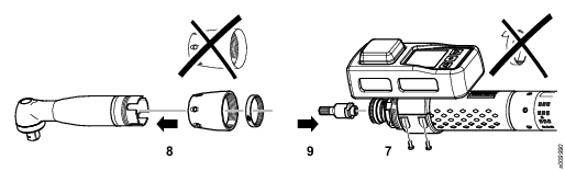
Remove the angle head.
Remove the circlip and the cap nut.
Remove the shaft and the plastic protection.
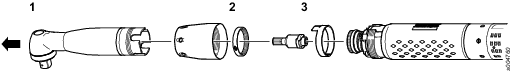
Screw on the cutting tool.

Cut the insulation. The flex cable is protected under a shield.

Assemble the accessory. Start by fitting the lower half in the correct position.

Fold the upper half in the correct position and tighten the 2 screws (1.8 Nm).
Assemble the new shorter cap nut and the circlip on the angle head.
Assemble the shaft and the angle head on the tool. Tighten the cap nut to specified torque.
Initial Configuration
User Instructions
The accessory is configured in the ILT Base Station. See ILT Base Station manual for further information.
Operation
Ergonomic Guidelines
Consider your workstation as you read through this list of general ergonomic guidelines to identify areas for improvement in posture, component placement, or work environment.
Take frequent breaks and change work positions frequently.
Adapt the workstation area to your needs and the work task.
Adjust for a convenient reach range by determining where parts and tools need to be located to avoid static load.
Use workstation equipment such as tables and chairs appropriate for the work task.
Avoid work positions above shoulder level or with static holding during assembly operations.
When working above shoulder level, reduce the load on the static muscles by lowering the weight of the tool, using for example torque arms, hose reels or weight balancers. You can also reduce the load on the static muscles by holding the tool close to the body.
Take frequent breaks.
Avoid extreme arm or wrist postures, particularly during operations requiring a degree of force.
Adjust for a convenient field of vision that requires minimal eye and head movements.
Use appropriate lighting for the work task.
Select the appropriate tool for the work task.
In noisy environments, use ear protection equipment.
Use high-quality inserted tools and consumables to minimize exposure to excessive levels of vibration.
Minimize exposure to reaction forces.
When cutting:
A cut-off wheel can get stuck if the cut-off wheel is bent or not guided properly. Use the correct flange for the cut-off wheel and avoid bending the cut-off wheel during operation.
When drilling:
The drill might stall when the drill bit breaks through. Use support handles if the stall torque is high. The safety standard ISO11148 part 3 recommends using a device to absorb a reaction torque above 10 Nm for pistol grip tools and 4 Nm for straight tools.
When using direct-driven screwdrivers or nutrunners:
Reaction forces depend on the tool settings and joint characteristics. Strength and posture determine the amount of reaction force that an operator can tolerate. Adapt the torque setting to the operator's strength and posture and use a torque arm or reaction bar if the torque is too high.
In dusty environments, use a dust extraction system or wear a mouth protection mask.
Service
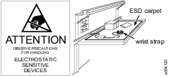
Preventing ESD Problems
The components inside the product and controller are sensitive to electrostatic discharge. To avoid future malfunction, make sure that service and maintenance is carried out in an ESD approved work environment. The figure below shows an example of an appropriate service work station.
Maintenance Instructions
Service Recommendations
Preventive maintenance is recommended at regular intervals. See the detailed information on preventive maintenance. If the product is not working properly, take it out of service and inspect it.
If no detailed information about preventive maintenance is included, follow these general guidelines:
Clean appropriate parts accurately
Replace any defective or worn parts
Recycling
Environmental Regulations
When a product has served its purpose it has to be recycled properly. Dismantle the product and recycle the components in accordance with local legislation.
Batteries shall be taken care of by your national battery recovery organization.
Recycling Information
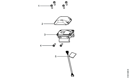
Position | Part | Remark | Recycle as |
|---|---|---|---|
1 | Screws | Metal, steel | |
2 | Housing | Plastic, other, PA | |
3 | ILT Tag attachment | Metal, aluminum | |
4 | Screws | Metal, steel | |
5 | Electronics module | Circuit board and cable | Electric |