ETF SL21-04-226-SF
Product Information
General Information
Symbols on the Tool
The symbols on the tool have the following meanings:
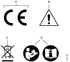
A | Directive 2006/42/EC on Machinery specifies the essential health and safety requirements the product has to meet in order for the manufacturer to affix the CE marking. |
B | When operating the device be sure to use caution. |
C | The symbol indicates that parts within the product must be handled in accordance with the WEEE Directive. |
D | Read the instruction manual/booklet before starting work or before operating equipment or machinery. |
Safety Signal Words
The safety signal words Danger, Warning, Caution, and Notice have the following meanings:
DANGER | DANGER indicates a hazardous situation which, if not avoided, will result in death or serious injury. |
WARNING | WARNING indicates a hazardous situation which, if not avoided, could result in death or serious injury. |
CAUTION | CAUTION, used with the safety alert symbol, indicates a hazardous situation which, if not avoided, could result in minor or moderate injury. |
NOTICE | NOTICE is used to address practices not related to personal injury. |
Warranty
Product warranty will expire 12+1 months after dispatch from Atlas Copco's Distribution Center.
Normal wear and tear on parts is not included within the warranty.
Normal wear and tear is that which requires a part change or other adjustment/overhaul during standard tools maintenance typical for that period (expressed in time, operation hours or otherwise).
The product warranty relies on the correct use, maintenance, and repair of the tool and its component parts.
Damage to parts that occurs as a result of inadequate maintenance or performed by parties other than Atlas Copco or their Certified Service Partners during the warranty period is not covered by the warranty.
To avoid damage or destruction of tool parts, service the tool according to the recommended maintenance schedules and follow the correct instructions.
Warranty repairs are only performed in Atlas Copco workshops or by Certified Service Partners.
Atlas Copco offers extended warranty and state of the art preventive maintenance through its ToolCover contracts. For further information contact your local Service representative.
For electrical motors:
Warranty will only apply when the electric motor has not been opened.
Website
Information concerning our Products, Accessories, Spare Parts and Published Matters can be found on the Atlas Copco website.
Please visit: www.atlascopco.com.
ServAid
ServAid is a portal that is continuously updated and contains Technical Information, such as:
Regulatory and Safety Information
Technical Data
Installation, Operation and Service Instructions
Spare Parts Lists
Accessories
Dimensional Drawings
Please visit: https://servaid.atlascopco.com.
For further Technical Information, please contact your local Atlas Copco representative.
Safety Data Sheets MSDS/SDS
The Safety Data Sheets describe the chemical products sold by Atlas Copco.
Please consult the Atlas Copco website for more information www.atlascopco.com/sds.
Country of Origin
For the Country of Origin, please refer to the information on the product label.
Dimensional Drawings
Dimensional Drawings can be found either in the Dimensional Drawings Archive, or on ServAid.
Please visit: http://webbox.atlascopco.com/webbox/dimdrw or https://servaid.atlascopco.com.
Overview
Intended use of the Fixtured Tightening Module
This product is designed to feed and hold the screws in position and apply the specified Torque to the joint in an automated process. The tightening process is controlled by the Power Focus 6000. No other use is permitted.
The partly completed machine is a fixtured screw feeding system intended for producing screw connections. The screw feeding is proceeded automatically by a Screw Feeding Unit. The Fixtured Screw Feeding Tightening Module and the Screw Feeding Unit are powered and controlled by the Power Focus 6000 and customer PLC (Programmable Logic Controller).
The tightening module should be used only indoors.
The tightening module should be put into operation only with the system components described here.
Permitted use of the Fixtured Tightening Module components
Fixtured Tightening Module and Driving Tool - Requires a defined torque or a defined angle of rotation.
Cables (electrical) - Provides electrical supply and controls the screw fastening system.
Hoses (pneumatic) - Supplies the Fixtured Tightening Module with pneumatic energy from the Screw Feeding Unit.
Feeding Tube - Transports fasteners from the Screw Feeding Unit to the feeding head.
Power Focus 6000 - Controls and monitors the screw fastening process.
Screw Feeding Unit - Feeds the Fixtured Tightening Module with screws.
System Description
The Fixtured Screw Feeding System consists of the Fixtured Tightening Module, Driving Tool, Power Focus 6000, Feeder, external Valve Control Unit, cables, and hoses. It is part of Atlas Copco’s Smart Connected Assembly concept and supports industrial production environments to become more efficient, ergonomic, and maximize the production output.
Fixtured Tightening Module
The Fixtured Tightening Module carries out the automatic feeding process. It consists of the following parts:
Feeding Head
Head-stroke and Bit-stroke version for fixed stations
Bit-stroke version for robot/cobot
The Fixtured Tightening Module components and functions are explained in the table below:

No | Components | Functions |
1 | Bit | Transmits the Torque to the screw. |
2 | Aligning Jaws | Guides the air-blown screw during the screw tightening process. The Aligning Jaws are connected to their holders with tension pins. The spring in the holders closes the Aligning Jaws. |
3 | Swivel Arm | Holds and loads the next screw while the previous screw is being tightened. The Swivel Arm guides the air-blown screws into the Aligning Jaws of the Feeding Head while it is in the loading position. In the working position, the Swivel Arm is swirled out by the Bit movement. |
4 | Feeding Head (in blue color) | Receives the screws through the swivel arm. The Aligning Jaws attached to the jaw holders, and thereby the feeding head guide the shift, and hold the screw in place for the bit to engage. |
5 | Swivel Arm Holder | Holds the Swivel Arm. |
6 | Quick-change Coupling | Helps to change the Feeding Head and Bit Assembly. |
7 | Feeding Tube Connector | Connects the Feeding Tube. |
8 | Sleeve | Helps to change the angle positions of the Feeding Head. Using these screws, the angle positions of the Feeding Head can be changed in -45°, -90°, 0°, 45°, and 90° degrees. Refer to the Angle Positions of the Feeding Head image below the table. |
9 | Feeding Tube | Transports the screws from the Screw Feeding Unit to the Swivel Arm by the pressurized air. |
10 | Ring Sensor | Detects the screw at the end of the Feeding Tube. |
11 | Inductive Sensor | Detects whether the Bit is completely retracted. |
12 | Stroke Position Sensor | Detects the position of the Bit-stroke. |
Bit-stroke version
The Bit-stroke only allows movement of the Bit in the front to push the screw through the jaws. It is used and mounted on robots or Cartesian slides that provide the Z-axis motion to the part.

Description | Value |
Total weight including QST34 Driving Tool | 4.3 kg |
Total weight without Driving Tool | 4.3 kg – 2 kg = 2.3 kg |
Maximum Torque of the Screw Feeding Head | 10 Nm |
Head-stroke version
The Head-stroke provides additional axis movement to bring the Feeding Head closer towards the tightening location. Thereby, the motor stays stationary and only the Feeding Head moves. It is used and mounted in stand-alone cell assembly and palletized assembly lines.

Description | Value |
Head-stroke | 48 mm |
Total weight including QST34 Driving Tool | 6 kg |
Total weight without Driving Tool | 6 kg - 2 kg = 4 kg |
Maximum Torque of the Feeding Head | 10 Nm |
Driving Tool
The Driving Tool generates the rotary motion and provides Torque which is transmitted to the Feeding Head via the Drive Shaft.

No. | Component | Function |
1 | Drive Shaft | Geared shaft of the rotary drive |
The different part numbers, model numbers, torque range, and speed of fixtured driving tools are specified in the below table:
Part Number | Model Number | Torque Range (Nm) | Speed (rpm) |
8434320084 | ETF SL21-01-226-SF | 0.3-1.2 | 3000 |
8434320085 | ETF SL21-04-226-SF | 0.8-4 | 1600 |
8434320086 | ETF SL21-07-226-SF | 1.5-7.5 | 970 |
8434320087 | ETF SL21-10-226-SF | 2-10 | 720 |
8434320088 | ETF SL21-01-256-SF | 0.3-1.2 | 3000 |
8434320089 | ETF SL21-04-256-SF | 0.8-4 | 1600 |
8434320090 | ETF SL21-07-256-SF | 1.5-7.5 | 970 |
8434320091 | ETF SL21-10-256-SF | 2-10 | 720 |
Part Number | Model Number | Torque Range (Nm) | Speed (rpm) |
4028001007 | QST34-20CT-SF-226 | 4 - 20 | 1000 |
4028001016 | QST34-20CT-SF-256 | 4 - 20 | 1000 |
4028001017 | QST34-20CTTA-SF-226 | 4 - 20 | 1000 |
4028001022 | QST34-20CTTA-SF-256 | 4 - 20 | 1000 |
4028001014 | QST34-8CT-SF-226 | 2 - 8 | 3000 |
4028001015 | QST34-8CT-SF-256 | 2 - 8 | 3000 |
4028001020 | QST34-8CTTA-SF-226 | 2 - 8 | 3000 |
4028001021 | QST34-8CTTA-SF-256 | 2 - 8 | 3000 |
Main Components of the Fixtured Screw Feeding System
The individual components or the system composition can be customer specific, and may therefore differ from the components shown here.
The Fixtured Screw Feeding System consists of the following main components (Bit-stroke):

No. | Components | Functions |
1 | Screw Feeding Tightening Module
| To carry out the tightening process. |
2 | Power Focus 6000 | To control and monitor the screw tightening process. |
3 | Screw Feeding Unit | To transport, sort, separate, and feed the screws into the Fixtured Tightening Module using compressed air. |
4 | Valve Control Unit | To control the electrical connections and pneumatic connections including the valves and fieldbus. |
5 | Tool Cable | Electrical connection between the Power Focus 6000 and the Fixtured Tightening Module |
6 | Air Connection | Air supply for the Valve Control Unit driven by the Screw Feeding Unit. |
7 | Air Connection | Air Connection for Forward and Return Bit Stroke between the Fixtured Tightening Module and the Valve Control Unit. |
8 | Connection Cable | Electrical connection between the Power Focus 6000 and the Screw Feeding Unit. Once the Power Focus 6000 is switched ON, the screw feeding unit gets an activation signal. |
9 | Fieldbus Connection | Electrical connection between the Power Focus 6000 and the Screw Feeding Unit. |
10 | Feeding Tube | Pneumatic transport of screws from the Screw Feeding Unit to the Fixtured Tightening Module |
11 | Signal Line | Communication between the Screw Feeding Unit and the Valve Control Unit. |
12 | Signal Line | Electrical connection between the Fixtured Tightening Module and the Valve Control Unit. The ring sensor detects the screws at the end of the Feeding Tube. |
13 | Signal Line | Electrical connection between the Fixtured Tightening Module and the Valve Control Unit. The inductive sensor is for the Bit-stroke retracted position. |
The Fixtured Screw Feeding System consists of the following main components (Head-stroke):

No. | Components | Functions |
1 | Fixtured Tightening Module
| To carry out the tightening process. |
2 | Power Focus 6000 | To control and monitor the screw tightening process. |
3 | Screw Feeding Unit | To transport, sort, separate, and feed the screws into the Fixtured Tightening Module using compressed air. |
4 | Valve Control Unit | To control the pneumatic and electrical connections. For example, Bit-stroke and Head-stroke. |
5 | Tool Cable | Electrical connection between the Power Focus 6000 and the Fixtured Tightening Module. |
6 | Air Connection | Air supply for the Valve Control Unit driven by Screw Feeding Unit. |
7 | Air Connection | Air Connection for Forward and Return Bit-stroke and Head-stroke between the Fixtured Tightening Module and the Valve Control Unit. |
8 | Connection Cable | Electrical connection between the Power Focus 6000 and the Screw Feeding Unit. Once the Power Focus 6000 is switched ON, the screw feeding unit gets an activation signal. |
9 | Fieldbus Connection | Electrical connection between the Power Focus 6000 and the Screw Feeding Unit. |
10 | Feeding Tube | Pneumatic transport of screws from the Screw Feeding Unit to the Fixtured Tightening Module. |
11 | Signal Line | Communication between the Screw Feeding Unit and the Valve Control Unit. |
12 | Signal Line | Electrical connection between the Fixtured Tightening Module and the Valve Control Unit. The ring sensor detects the screws at the end of the Feeding Tube. |
13 | Signal Line | Electrical connection between the Fixtured Tightening Module and the Valve Control Unit. The inductive sensor is for the Head-stroke retracted position. |
14 | Signal Line | Electrical connection between the Fixtured Tightening Module and the Valve Control Unit. The inductive sensor is for the Head-stroke extended position. |
15 | Signal Line | Electrical connection between the Fixtured Tightening Module and the Valve Control Unit. The inductive sensor is for the Head-stroke retracted position. |
For more information about the Screw Feeding Unit, see product information of the Screw Feeding Unit.
For more information about the Power Focus 6000, see product information of the Power Focus 6000.
The Tensor System
The Tensor system consists of a range of tightening tools powered by brushless electric motors and different drive units.
Motors are available in different sizes. All tools are protected from overheating of the motor. Electrical protection system is based on an earth fault circuit brake, Earth Fault Protector (EFP). The EFP senses small current leakage (>30mA) and if leakage occurs, the drive is switched off (30ms). Changing, interfering or tampering with the protection system voids all warranty and obligations from Atlas Copco. Trouble-shooting and re-start of the system may only be carried out by an authorized person. Check the function of the EFP on a regular basis by pressing the trip-button. The EFP should switch off accordingly.
Technical Product Data
Technical Product Data can be found on either ServAid, or the Atlas Copco website.
Please visit: https://servaid.atlascopco.com or www.atlascopco.com.
Operating Sequences
The two different operating sequences of the Fixtured Tightening Module are described below:
No. | Operating Sequence |
1 | Bit-stroke |
2 | Bit and Head-stroke |
Bit-stroke Operating Sequence
The operation gets triggered by an external control unit or PLC (Programmable logic controller).
The Bit-stroke moves forward with the Bit rotation and pushes the Swivel Arm out of the Feeding Head. When the swivel arm is pushed out, it allows to reload the next screw.
The Bit-stroke pushes the screws out of the Aligning Jaws during the tightening process.
The tightening process gets completed.
The Bit-stroke moves backward to the loading position.
The next screw gets carried from the Swivel Arm into the Aligning Jaws.
Bit and Head-stroke Operating Sequence
The operation gets triggered by an external control unit or PLC (Programmable logic controller).
The Head-stroke moves forward from the idle position to the working position.
The Bit-stroke moves forward with the Bit rotation and pushes the Swivel Arm out of the Feeding Head. When the swivel arm is pushed out, it allows to reload the next screw.
The Bit-stroke pushes the screws out of the Aligning Jaws during the tightening process.
The Bit-stroke and the Head-stroke move backward to the idle position.
The tightening process gets completed.
The Bit-stroke moves backward to the loading position.
The next screw gets carried from the Swivel Arm into the Aligning Jaws.
Installation
Installation Requirements
Socket Release Function
It is recommended to use the socket release function on all the ETP ST101 tools. When the function is enabled, the socket rotates backwards 3° after a completed tightening. The aim is to reduce tension on the reaction bar and to make it easier to remove the tool.
The socket release function is turned on from the controller.
On Power Focus 4000:
-
Push the Prog button
-
Use the navigation buttons to follow the path > Pset > Programming+ > Options > Socket release > Mode On
Tool Display
The tool display is turned on from the controller.
On Power Focus 4000:
Push the Prog button
Use the navigation buttons to follow the path > Tool > Configuration > Accessory bus > ST bus > Mode
Connecting the Tool
The tool should, via its correct Power Focus drive unit, be connected to the mains, 230V/50Hz alternatively 115V/ 60Hz, single phase. See instructions for your Power Focus drive unit.
Grounding
If the tool is mounted in a handheld or hand guided fixture, the fixture should be connected to the drive using a separate 2.5mm2 grounding cable.
Installation Instructions
Installation
This chapter provides installation instructions of the Fixtured Tightening Module.
Please read all the below safety messages before installation.
Mounting the Fixtured Tightening Module
Mount the Fixtured Tightening Module using the below mounting plate. Mounting is possible on a robotic device or a frame.

Position | Dimension | Tightening Torque |
1 | 4 DIN 912 M6X18 | 10 Nm |
2 | 2 ISO 8734 - D6X16 pin | Press the pin |
3 | 2 DIN 6 912 M8X20 | 25 Nm |
The four center screws DIN 912 M6X18 with threads are used to mount the mounting plate on the intended location. The tightening torque should be 10 Nm. It is possible to mount the mounting plate either from the front side or from the back side using the four center screws with threads.
From the your side, the two pins ISO 8734 - D6X16 in the distance of 4-10mm should be used to align the mounting plate.
The two screws DIN 6 912 M8X20 on the left side shown in the above image are used to mount the Fixtured Tightening Module on the mounting plate. The tightening torque should be 25 Nm.
Reaction Force
Below is the reaction force needed for the bit-stroke version which has to be absorbed by the external fixture or other movable parts.
Bit-stroke Pressure | Static Reaction Force | Reaction Force including dynamic reserve |
4 bar | 200 N | 400 N |
5 bar | 240 N | 440 N |
6 bar | 290 N | 490 N |
When a new head-stroke function is added, the bit-stroke force must not exceed the head-stroke force.
Mounting the Feeding Tube with the adapter

Positions | Components |
1 | Fork Pressure Plate |
2 | Feeding Tube Connector |
3 | Feeding Tube |
Angle Positions of the Feeding Head
Through the Feeding Tube, the screws are transported by pressurized air from the Screw Feeding Unit to the Swivel Arm of the Fixtured Tightening Module. The Feeding Tube connector is clamped with a fork pressure plate onto the holder. The pressure plate is fixed with two M4x8 Allen screws (M4 = 3 Nm). The position of the feeding head can be adjusted to meet the accessibility of the application.

Orientation of Air Connections
The Orientation of air connections is project specific.


Cable Management
Fitting of the Tool Cable
Make sure that the tool cable is of correct type.
Align the cable connector using the two asymmetrically positioned heads on the connector to fit in the slots in the tool handle.
Tighten the lock nut.
Make sure that the connection is correct by pulling, pushing, and turning the cable connector (there should be no movement).
The tool has a built in electronic memory chip that will transmit the torque transducer calibration value and angle pulses to the POWER FOCUS/drive unit. Any changes made of these values in the POWER FOCUS while the tool is connected will be stored in the tool memory.
Connecting the Screw Feeding Tightening Module to the Feeding Tube
Through the Feeding Tube, the screws are transported by compressed air from the Screw Feeding Unit to the Swivel Arm of the Screw Feeding Tightening Module. The Feeding Tube is connected by removing the fork plate, inserting the feeding tube connector, and reattaching the fork plate.
Installation Workflow
Connect the Driving Tool to the tightening controller.
Connect the Feeding tube to the Fixtured Tightening Module.
Connect all the sensor cables and pneumatic lines to the Valve Control Unit.
Connect the Valve Control Unit to the Feeder with the pneumatic supply cable.
Refer Main Components chapter
Operation
Ergonomic Guidelines
Consider your workstation as you read through this list of general ergonomic guidelines to identify areas for improvement in posture, component placement, or work environment.
Take frequent breaks and change work positions frequently.
Adapt the workstation area to your needs and the work task.
Adjust for a convenient reach range by determining where parts and tools need to be located to avoid static load.
Use workstation equipment such as tables and chairs appropriate for the work task.
Avoid work positions above shoulder level or with static holding during assembly operations.
When working above shoulder level, reduce the load on the static muscles by lowering the weight of the tool, using for example torque arms, hose reels or weight balancers. You can also reduce the load on the static muscles by holding the tool close to the body.
Take frequent breaks.
Avoid extreme arm or wrist postures, particularly during operations requiring a degree of force.
Adjust for a convenient field of vision that requires minimal eye and head movements.
Use appropriate lighting for the work task.
Select the appropriate tool for the work task.
In noisy environments, use ear protection equipment.
Use high-quality inserted tools and consumables to minimize exposure to excessive levels of vibration.
Minimize exposure to reaction forces.
When cutting:
A cut-off wheel can get stuck if the cut-off wheel is bent or not guided properly. Use the correct flange for the cut-off wheel and avoid bending the cut-off wheel during operation.
When drilling:
The drill might stall when the drill bit breaks through. Use support handles if the stall torque is high. The safety standard ISO11148 part 3 recommends using a device to absorb a reaction torque above 10 Nm for pistol grip tools and 4 Nm for straight tools.
When using direct-driven screwdrivers or nutrunners:
Reaction forces depend on the tool settings and joint characteristics. Strength and posture determine the amount of reaction force that an operator can tolerate. Adapt the torque setting to the operator's strength and posture and use a torque arm or reaction bar if the torque is too high.
In dusty environments, use a dust extraction system or wear a mouth protection mask.
Operating Instructions
Operation
In this chapter, the operational safety instructions, general instructions for the operator, and the workflow of the module are described.
Please read the below safety instructions before Operation.
General Instructions for the Operator
Make sure you are familiar with the operator’s instructions before you use this tool.
The tool together with any attachments or accessories, must never be used for anything other than the designed purpose.
All locally legislated safety rules regarding installation, operation, and maintenance shall be respected at all times.
This product is only intended for industrial use and shall only be operated indoor in dry rooms. This product must not be used in explosive atmospheres.
Keep hands, long hair, and other objects away from the rotating socket.
Make sure that the tool is in good working order and that the controller is correctly programmed before use to avoid unexpected behaviour from the tool which may result in operator injury.
Do not use force when handling the Screw Feeding Tightening Module.
Use only accessories recommended by the manufacturer. The connection of unsuitable accessories is a potential source of danger.
Check the Screw Feeding Tightening Module for any incorrect adjustments, jammed moving parts, damage, and other faults that could affect the operation of the device.
Operating
Make sure that the tool is in correct working order and that the controller is correctly programmed to avoid unexpected behaviour from the tool, which may result in operator injury.
Check that the tool is in the correct running direction by looking at the function light situated above the tool handle, by turning the reverse ring (only for ETV/ETD DS or by turning the arm on the trigger knob (only for ETP DS).
The soft-start function facilitates entering the screw head and thread.
The duration of the soft start is adjustable, see the manual for the drive unit.
The tool is equipped with signal lights,
Green = OK tightening
Yellow = Warning – low torque (not for ES)
Red = Warning – high torque
Orange = Function indicator (only for SL and DL)
Blue = Function indicator (only for SL)
Service
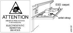
Preventing ESD Problems
The components inside the product and controller are sensitive to electrostatic discharge. To avoid future malfunction, make sure that service and maintenance is carried out in an ESD approved work environment. The figure below shows an example of an appropriate service work station.
Maintenance Instructions
Removing the Bit and Bit Adaptor
Removing the Bit from the Threaded Sleeve
There are two ways of removing the Bit from the Threaded Sleeve.
Hold the Threaded Sleeve with the Hook Wrench, and use pliers to unscrew the Bit from the Threaded Sleeve.
Another method is to clamp the Bit and unscrew the Threaded Sleeve with the Hook Wrench.
Perform step 1 in the reversed order to attach the new Bit to the Threaded Sleeve. Make sure that the Bit is not damaged during this procedure.
Make sure that the Bit, Threaded Sleeve, and new Bit Adaptor are correctly mounted together.
Insert the Bit Assembly into the Screw Feeding Front Part using the Bit Quick-change Coupling.

Positions | Components |
1 | Hook Wrench |
2 | Threaded Sleeve |
3 | Mounting Tool |
4 | Bit Adaptor |
5 | Bit |
Removing the Bit Adaptor
Hold the Threaded Sleeve with the Hook Wrench and make sure the hooks are into the holes.
Use the Mounting Tool to grip the Bit Adaptor and release it from the Threaded Sleeve.
Tightening Torque Specifications
Dimension | Tightening Torque (Nm) |
M4 | 3 |
M5 | 6 |
M6 | 10 |
M8 | 25 |
Maintaining the Feeding Head
Removing and Replacing the Feeding Head
The Feeding Head needs to be repaired in case of damage. An inadequately maintained Feeding Head is a source of danger.
Follow the below steps to remove and replace the Feeding Head:
Push the Swivel Arm aside and pull the sleeve of the Quick-change Coupling backwards, and then pull off the Feeding Head (in blue color).
Attach the clean or the new Feeding Head and then release the sleeve of the Quick-change Coupling.
Make sure that the Feeding Head is correctly attached by turning and pulling it gently. The Feeding Head should remain attached to the tightening module.

Cleaning and Checking the Feeding Head
Clear the dirts of the Feeding Head using an industrial cleaner and a cloth.
Inspect the Feeding Head visually and check for damage. If damaged, the Feeding Head or the damaged components must be replaced.


Overhaul
Service must only be carried out by qualified personnel who have access to the Service instruction and/or have been trained for service on Tensor tools.
The electric motor is a sealed unit and may under no circumstances be opened by anyone else than Atlas Copco Industrial Technique AB!
If you decide that the electric motor is defect or in need of service, return the complete motor unit to Atlas Copco Industrial Technique for replacement.
Motors which have been opened by anyone else than Atlas Copco Industrial Technique will not be serviced.
Overhaul and preventive maintenance is recommended at regular intervals once per year or after maximum 250.000 tightening depending on which occurs sooner. More frequent overhaul may be needed if the machine is used in heavy-duty operations. If the machine not is working properly, it should immediately be taken away for inspection.
When dismantling the tool always use the specially designed service tool 4080 0848 80, (two service tools are required).
Overhaul for small head (-SH) models: Overhaul and preventive maintenance is recommended at regular intervals, once per year or after a maximum of 100.000 tightenings, depending on which occurs sooner. More frequent overhaul may be needed if used at high torque, high cycle rate or long tightening time. If the machine is not working properly, it should immediately be taken away for inspection.
Service Recommendations
Preventive maintenance is recommended at regular intervals. See the detailed information on preventive maintenance. If the product is not working properly, take it out of service and inspect it.
If no detailed information about preventive maintenance is included, follow these general guidelines:
Clean appropriate parts accurately
Replace any defective or worn parts
Lubrication Instructions
Lubrication
Lubricate according to the Lubrication Guide at each service occasion.
For more information, see Spare Parts section in ServAid - https://servaid.atlascopco.com.
Repair Instructions
Repair
Repair must only be carried out by qualified authorised personnel. For further information contact your local Atlas Copco sales representative.
Troubleshooting
Power Focus 6000
Is the unit switched on? Check the earth fault circuit breaker behind the front door. Should it have tripped, make sure to find the primary fault before resuming operation. Check that the wiring on the remote start connector is correct. For further information see 9836 4954/9836 7446.
Power Focus 3000/4000
Is the POWER FOCUS switched on and in RUN mode? Check that the correct POWER FOCUS is used (ST31/ST32/ST61/STR31/STR61-Tensor3-7, ST81-Tensor8-9). Check the fuses for the drive part. Check Drive parameters, refer to the User Guide of the POWER FOCUS/ drive unit. Check the earth fault circuit breaker on the backside of the drive. Should it have tripped, make sure to find the primary fault before resuming operation. Check that the wiring on the remote start connector is correct. For further information see 9836 2258.
Power Focus 600/6000
Is the unit switched on? Check the earth fault circuit breaker behind the front door. Should it have tripped, make sure to find the primary fault before resuming operation. Check that the wiring on the remote start connector is correct. For further information see 9836 4954/9836 7446.
Overheated Tool
With proper adjustment the tool can handle any normal line jobs that an operator sustains. What can cause overheating are combinations of some factors: torque above rated, too low speed, too long ramp time (motor has to give high torque for a long time), very high prevailing torque, very soft joints, short cycle time. To correct, look over speed, ramp time, tightening strategy. One stage and Ergoramp are most heat conserving when applicable. Please refer to the User Guide of your POWER FOCUS. If the above corrections are not enough, choose a tool of the next higher capacity.
Recycling
Environmental Regulations
When a product has served its purpose it has to be recycled properly. Dismantle the product and recycle the components in accordance with local legislation.
Batteries shall be taken care of by your national battery recovery organization.