MTRwrench 85
Product Information
General Information
Safety Signal Words
The safety signal words Danger, Warning, Caution, and Notice have the following meanings:
DANGER | DANGER indicates a hazardous situation which, if not avoided, will result in death or serious injury. |
WARNING | WARNING indicates a hazardous situation which, if not avoided, could result in death or serious injury. |
CAUTION | CAUTION, used with the safety alert symbol, indicates a hazardous situation which, if not avoided, could result in minor or moderate injury. |
NOTICE | NOTICE is used to address practices not related to personal injury. |
Warranty
Product warranty will expire in 12+1 months after dispatch from Atlas Copco's Distribution Center.
Normal wear and tear on parts is not included within the warranty.
Normal wear and tear is that which requires a part change or other adjustment/overhaul during standard tool maintenance typical for that period (expressed in time, operation hours or otherwise).
The product warranty relies on the correct use, maintenance, and repair of the tool and its component parts.
Damage to parts that occurs as a result of inadequate maintenance or performed by parties other than Atlas Copco or their Certified Service Partners during the warranty period is not covered by the warranty.
To avoid damage or destruction of tool parts, service the tool according to the recommended maintenance schedules and follow the correct instructions.
Warranty repairs are performed only in Atlas Copco workshops or by Certified Service Partners.
Atlas Copco offers extended warranty and state-of-the-art preventive maintenance through its ToolCover contracts. For further information, contact your local Service representative.
For electrical motors:
Warranty will apply, only when the electric motor has not been opened.
Website
Information concerning our Products, Accessories, Spare Parts and Published Matters can be found on the Atlas Copco website.
Please visit: www.atlascopco.com.
ServAid
ServAid is a portal that is continuously updated and contains Technical Information, such as:
Regulatory and Safety Information
Technical Data
Installation, Operation and Service Instructions
Spare Parts Lists
Accessories
Dimensional Drawings
Please visit: https://servaid.atlascopco.com.
For further Technical Information, please contact your local Atlas Copco representative.
Country of Origin
For the Country of Origin, please refer to the information on the product label.
Dimensional Drawings
Dimensional Drawings can be found either in the Dimensional Drawings Archive, or on ServAid.
Please visit: http://webbox.atlascopco.com/webbox/dimdrw or https://servaid.atlascopco.com.
Overview
System Overview
The MTRwrench 85 is a mechanical click-wrench combined with an electronic torque transducer. The tightening programs are configured and assigned to the wrench with the Power Focus 6000 or with the Power Focus 8, which communicate wirelessly with the MTRwrench 85 using the MWR-KIT as gateway.
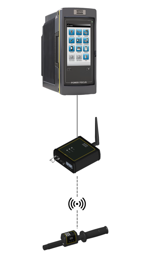
For more information on how to manage and configure the MTRwrench 85, refer to MWR-KIT Product Instructions, Power Focus 6000 User Guide and Power Focus 8 User Guide.
Tool Overview
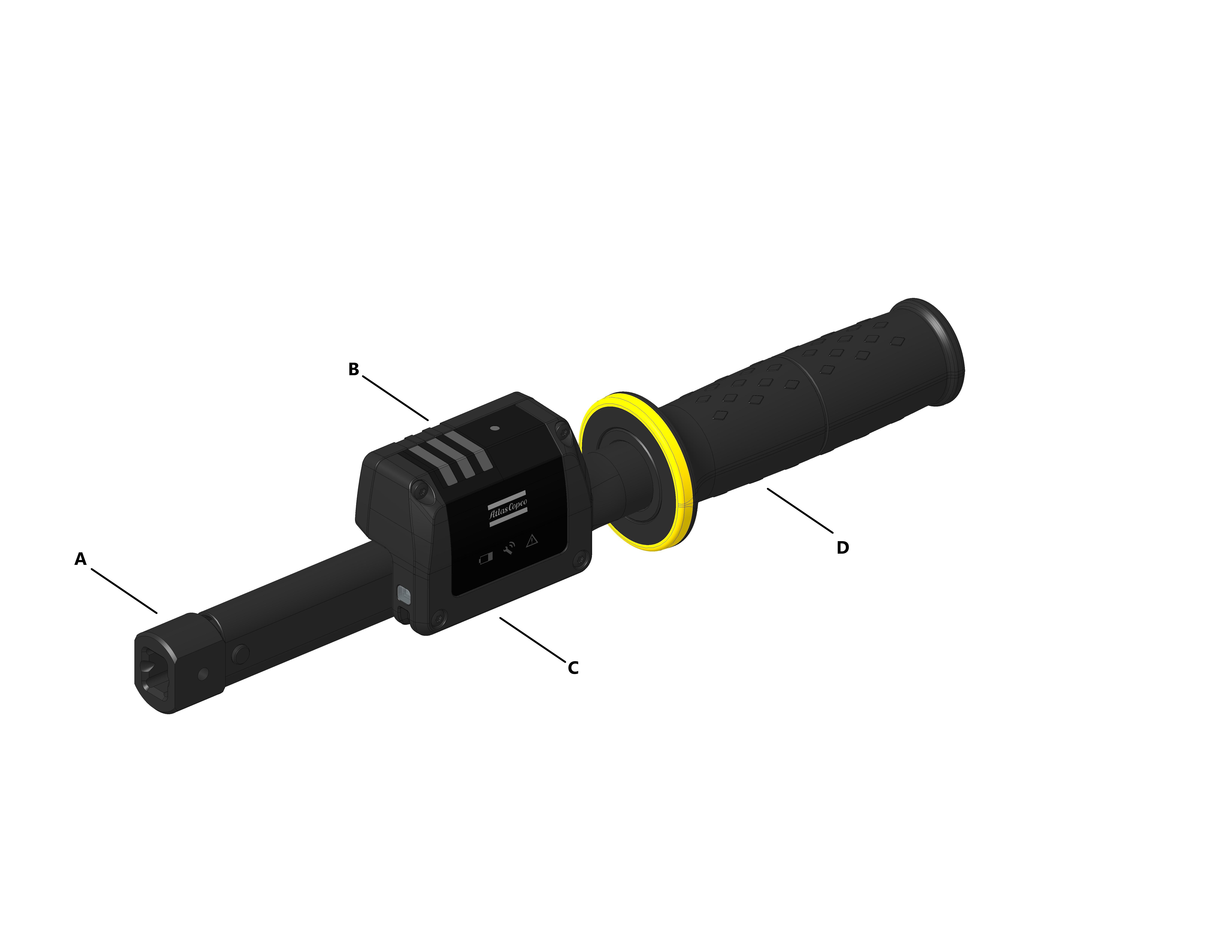
A | Drive | B | Battery housing |
C | HMI with LED Indicators | D | Handle |
LED Indicators Overview
The MTRwrench 85 HMI is equipped with four LED indicators that show different wrench statuses, and along with a set of three LED indicators that communicate progress and results of operations.
An additional Front Projection LED is available to communicate the results of tightening operations in situations where the operator cannot fully see the HMI.
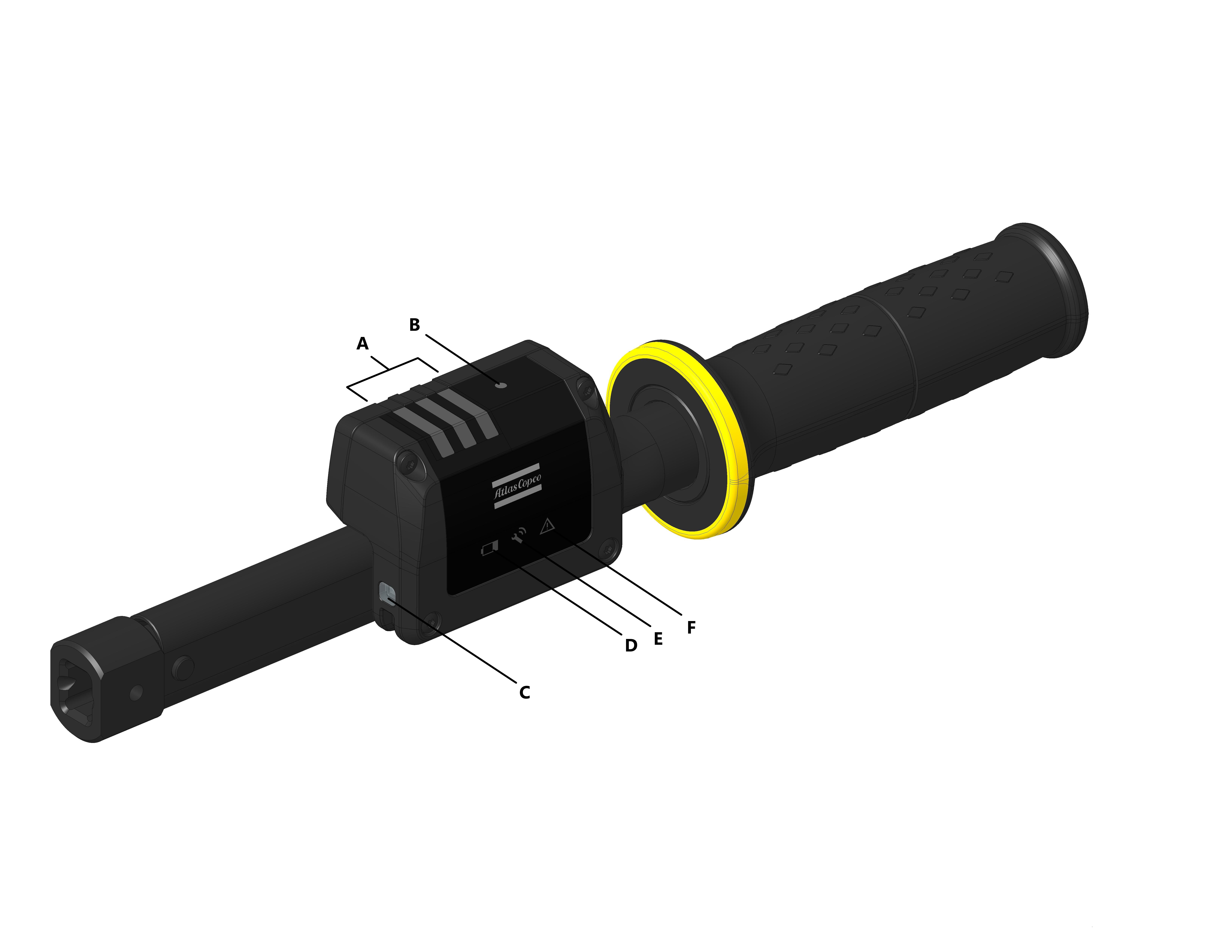
Position | Name | Main indications |
|---|---|---|
A | Progress LEDs |
|
B | Job Ready LED |
|
C | Front Projection LED |
|
D | Battery Level LED |
|
E | Radio Communication LED |
|
F | Error/Warning LED |
|
Battery Level LED Indicator
The MTRwrench 85 is equipped with a LED indicator that tells the operator if the battery level drops below certain thresholds.
The Battery Level LED behaves as follows:
LED Behavior | Battery charge level | Remark | |
|---|---|---|---|
Off |
| 11% / 15% / 35% - 100% | Battery level suitable for operations. The lower limit of the range depends on the "Low Battery [%]" configuration via MWR-KIT. |
Blinking red |
| 11% - 14/28% | Battery level low. The higher limit of the range depends on the "Low Battery [%]" configuration via MWR-KIT (disabled per default: in this case never blinks) |
Steady red |
| 0% - 10% | Battery empty. |


Radio Communication LED Indicator
The MTRwrench 85 is equipped with a LED indicator that notifies the operator on the wrench's wireless communication status.
The Radio Communication LED behaves as follows:
LED Behavior | LED Status | Meaning | |
|---|---|---|---|
OFF |
| Wireless communication off. | |
Breathing |
| Online: wireless communication on, wrench linked in coverage | |
Blinking |
| Offline: wireless communication on, wrench linked out of coverage | |
OFF | ON | ||
Slow Blinking |
| Wrench not in use: wireless communication on, wrench not linked | |
Long OFF | Short ON | ||


Job Ready LED Indicator
The MTRwrench 85 is equipped with a LED indicator that notifies the operator when a tightening program assigned by Power Focus 6000/Power Focus 8 has been successfully sent to the MTRwrench 85.
The Job Ready LED behaves as follows:
Wrench condition | LED Behavior | Meaning | |
|---|---|---|---|
Wrench inactive | Off |
| Tightening program missing. |
Wrench inactive | Steady blue |
| Tightening program received. Wrench ready to operate. |
Wrench active | Off |
| Tightening operation ongoing. |


Zero Adjustment LED Indicators
The MTRwrench 85 LED Indicators show the operator when a zero adjustment is required and communicate the progress, completion and possible errors of the zeroing process:
LED indicators | Meaning | Remark | |
|---|---|---|---|
Progress LEDs all blinking white |
| Zero adjustment required. | Place the wrench into the cradle. |
Progress LEDs turn on and off in sequence back and forth. |
| Zero adjustment ongoing. Firmware update in progress | Do not move the wrench. Do not apply any load to the wrench. |
Progress LEDs off. |
| Zero adjustment completed successfully. | - |
Progress LEDs blinking white |
| Zero adjustment failed due to wrench moving or to load being applied to the transducer. | Remove the wrench and place it again into the cradle to start a new zero adjustment. |
Progress LEDs steady red |
| Zero adjustment failed due to wrench moving or to load being applied to the transducer for a second time during the zero adjustment. | Remove the wrench and place it again into the cradle to start a new zero adjustment. |


 +
+ Charging LED Indicators
The MTRwrench 85 indicators, when the wrench is in the cradle and after the zeroing process has been completed, show the operator the status of the charging:
1 led blinking white |
| Battery charging from 0% to 30% |
1 led steady white and 2nd blinking white |
| Battery charging from 31% to 60% |
2 led steady white and 3rd blinking white |
| Battery charging form 61% to 90% |
3 led steady white |
| Battery charging from 91% to 100% |


Tightening Operations LED Indicators
During tightening operations, the MTRwrench 85 LED Indicators give the operator a visual feedback on the progress and result of the ongoing tightening operation:
Operation stage | LED indicators behavior | Meaning | |
|---|---|---|---|
Tightening program sent to wrench | Job Ready LED steady on |
| Wrench received the tightening program |
Tightening in progress | Progress LED 1 blinking white |
| 10-25% of torque reached or Loosening detected |
Tightening in progress | Progress LED 1 steady white |
| 25% of click torque reached |
Tightening in progress | Progress LED 1 steady white |
| 40% of click torque reached |
Tightening in progress | Progress LED 1 steady white |
| 55% of click torque reached |
Tightening in progress | Progress LED 1 steady white |
| 70% of click torque reached |
Tightening in progress | Progress LED 1 steady white |
| 85% of click torque reached |
Tightening completed successfully | All Progress LEDs blink off |
| 100% of click torque reached |
Tightening result | All Progress LEDs steady green |
| Result OK |
Tightening result | All Progress LEDs blinking red |
| Result Not OK Possible causes according to tightening strategy:
|


Errors and Warnings LED Indicators
The MTRwrench 85 Error/Warning LED indicator, along with the Progress LEDs, shows the operator of detected errors or damages.
LED indicators | Diagnosis | Corrective actions | |
|---|---|---|---|
Warning LED blinking red |
| Minor transducer overload | Place the wrench into the cradle to perform a zero adjustment. |
Progress LEDs all blinking red |
| Wrench locked due to major transducer overload | Stop running tightening operations and contact Atlas Copco Customer Service. |
Progress LEDs blinking white |
| Zero adjustment failed due to wrench moving or to load being applied to the transducer. | Remove the wrench and place it again into the cradle to start a new zero adjustment. |
Progress LEDs steady red |
| Zero adjustment failed due to wrench moving or to load being applied to the transducer for a second time during the zero adjustment. | Remove the wrench and place it again into the cradle to start a new zero adjustment. |
Progress LEDs off + Warning LED blinking red |
| Calibration or mechanical service required. | Send wrench to service |

Environmental Conditions
Indoor use only | |
Altitude | Up to 2000 m |
Ambient temperature range | +5 to +40 °C |
Maximum relative humidity 80 % for temperatures up to 31 °C decreasing linearly to 50 % relative humidity at 40 °C |
|
Product Data
Operating torque measuring range | 17 [N·m] - 85 [N·m] / 12.5 [lb·ft] - 62.7 [lb·ft] |
Drive | 9 x12 mm |
Overall length | 212 mm |
Weight | 496 g |
Operating torque range | from 20% to 100% of the capacity |
Mechanical click repeatability | ± 3% |
Torque measurement accuracy | ± 3% |
Overload capacity | 150 % of nominal capacity |
Maximum angular speed | 250 °/s |
Angle measurement accuracy | ± 3.6 ° / 360 ° (at 6 ° per second) |
Temperature stability of torque measurement | +10 °C to +40 °C (10 °F to 104 °F) |
Tightening results memory capacity | 10000 (maximum) |
Power supply | Rechargeable NiMH AA battery 1900mAh 1.2V |
Radio distance | Up to 20 m This distance can be influenced by various factor:
|
Dimensions
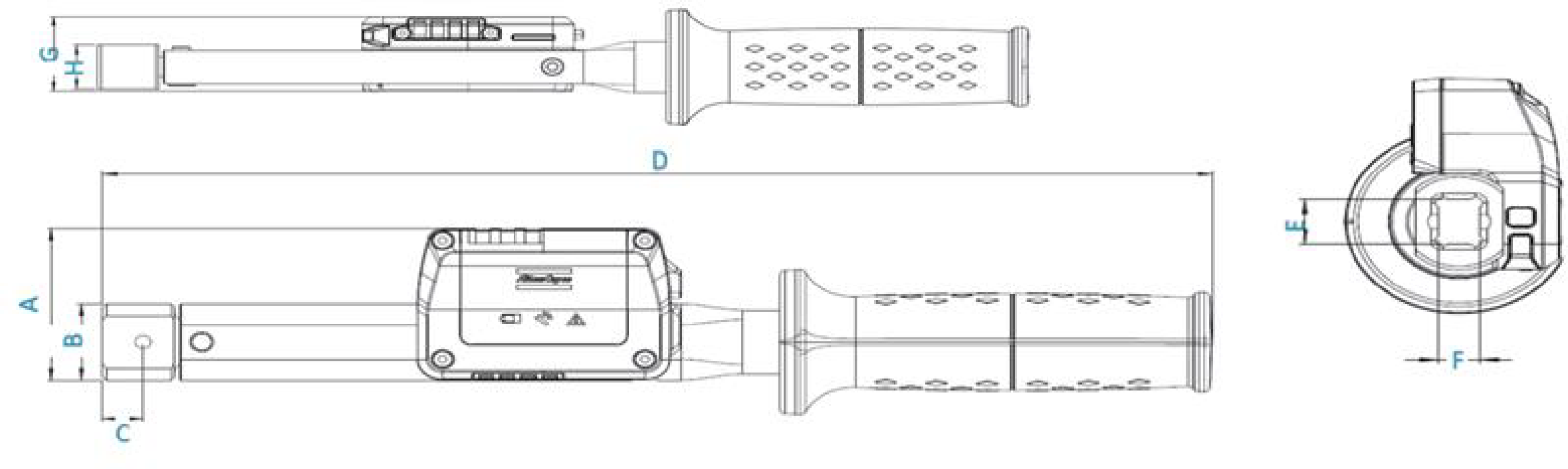
A [mm] | B [mm] | C [mm] | D [mm] | E [mm] | F [mm] | G [mm] | H [mm] |
|---|---|---|---|---|---|---|---|
52.5 | ⌀ 26.3 | 11.2 | 307.1 | 12 | 9 | 32.2 | 19 |
Radio Module Frequencies
Refer to the local Regulatory Domain for frequency selection.
Europe
Number | Channel | Frequency [MHz] | Data rate [bit/s] |
|---|---|---|---|
1 | 51 | 868.044 | 19200 |
2 | 52 | 868.088 | 19200 |
3 | 53 | 868.132 | 19200 |
4 | 54 | 868.176 | 19200 |
5 | 55 | 868.221 | 19200 |
6 | 56 | 868.265 | 19200 |
7 | 57 | 868.309 | 19200 |
8 | 58 | 868.353 | 19200 |
9 | 59 | 868.397 | 19200 |
10 | 60 | 868.442 | 19200 |
11 | 61 | 868.486 | 19200 |
12 | 62 | 868.530 | 19200 |
13 | 63 | 868.744 | 19200 |
14 | 64 | 868.788 | 19200 |
15 | 65 | 868.832 | 19200 |
16 | 66 | 868.876 | 19200 |
17 | 67 | 868.921 | 19200 |
18 | 68 | 868.965 | 19200 |
19 | 69 | 869.009 | 19200 |
20 | 70 | 869.053 | 19200 |
21 | 71 | 869.097 | 19200 |
22 | 72 | 869.142 | 19200 |
23 | 73 | 869.444 | 19200 |
24 | 74 | 869.488 | 19200 |
25 | 75 | 869.532 | 19200 |
USA
Number | Channel | Frequency [MHz] | Data rate [bit/s] |
|---|---|---|---|
1 | 1 | 902.132 | 19200 |
2 | 2 | 902.176 | 19200 |
3 | 3 | 902.220 | 19200 |
4 | 4 | 902.264 | 19200 |
5 | 5 | 902.308 | 19200 |
6 | 6 | 902.352 | 19200 |
7 | 7 | 902.396 | 19200 |
8 | 8 | 902.440 | 19200 |
9 | 9 | 902.484 | 19200 |
10 | 10 | 902.528 | 19200 |
11 | 11 | 902.572 | 19200 |
12 | 12 | 902.616 | 19200 |
13 | 13 | 902.660 | 19200 |
14 | 14 | 902.704 | 19200 |
15 | 15 | 902.748 | 19200 |
16 | 16 | 902.792 | 19200 |
17 | 17 | 902.836 | 19200 |
18 | 18 | 902.880 | 19200 |
19 | 19 | 902.924 | 19200 |
20 | 20 | 902.968 | 19200 |
21 | 21 | 903.012 | 19200 |
22 | 22 | 903.056 | 19200 |
23 | 23 | 903.100 | 19200 |
24 | 24 | 903.144 | 19200 |
25 | 25 | 903.188 | 19200 |
26 | 26 | 903.232 | 19200 |
27 | 27 | 903.276 | 19200 |
28 | 28 | 903.320 | 19200 |
29 | 29 | 903.364 | 19200 |
30 | 30 | 903.408 | 19200 |
31 | 31 | 903.452 | 19200 |
32 | 32 | 903.496 | 19200 |
33 | 33 | 903.540 | 19200 |
34 | 34 | 903.584 | 19200 |
35 | 35 | 903.628 | 19200 |
36 | 36 | 903.672 | 19200 |
37 | 37 | 903.716 | 19200 |
38 | 38 | 903.760 | 19200 |
39 | 39 | 903.804 | 19200 |
40 | 40 | 903.848 | 19200 |
41 | 41 | 903.892 | 19200 |
42 | 42 | 903.936 | 19200 |
43 | 43 | 903.980 | 19200 |
44 | 44 | 904.024 | 19200 |
45 | 45 | 904.068 | 19200 |
46 | 46 | 904.112 | 19200 |
47 | 47 | 904.156 | 19200 |
48 | 48 | 904.200 | 19200 |
Accessories
Compatible Battery
A rechargeable NiMH AA battery (1900 mAh, 1.2 V) provides power to the MTRwrench 85.
The tool is compatible with above mentioned rechargeable batteries.
It is recommended to use the rechargeable batteries with part number
4027 0048 20.
End-Fitting Tools
The MTRwrench 85 has a standard drive (9 x12 mm) compatible with different types of end-fitting tools.
To calculate the actual torque applied to a joint when using a specific end-fitting tool, while configuring the tightening program on Power Focus 6000/Power Focus 8 enter the end-fitting tool length measured (as shown in the picture below) Tool size field of the MWR tightening step.
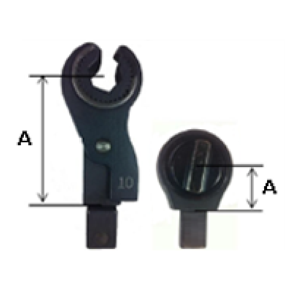
A | Tool size value to enter in the MWR tightening step on Power Focus 6000/Power Focus 8. | ||
For more information on how to configure tightening programs, refer to Power Focus 6000 User Guide or to Power Focus 8 User Guide according to the controller in use.
Installation
Initial Configuration
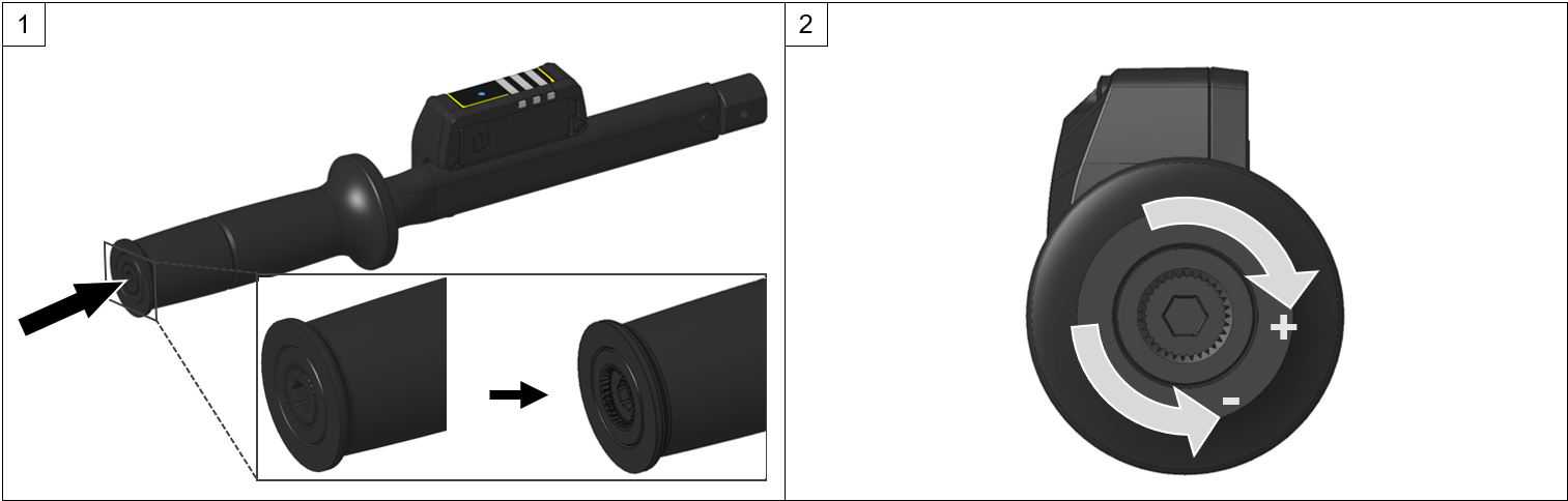
Adjusting the Click-Torque
Insert and push a MTRwrench setting key into the end of the MTRwrench 85 handle.

Part number of MTRwrench setting key: 8439004834.
Rotate the MTRwrench setting key clockwise to increase the click-torque, or counterclockwise to decrease the click-torque.
The torque range is indicated on the wrench's label.
Connecting the Wrench to MWR-KIT
For information on how to enable and manage the connection between MTRwrench 85 and MWR-KIT, refer to MWR-KIT Product Instructions.
Operation
Configuration Instructions
Configuring Tightening Programs
The MTRwrench 85 tightening programs are configured and managed via Power Focus 6000 or via Power Focus 8.
To communicate with Power Focus and receive tightening programs, the MTRwrench 85 must first be linked to an MWR-KIT connected to the Power Focus.
If during operations the MTRwrench 85 goes out of radio range, the wrench will continue working with the last tightening program assigned by the Power Focus and can store up to 10000 results. Once the MTRwrench 85 is back within radio range, the Power Focus retrieves the collected results and communicates any potential changes applied to the assigned tightening program during the out-of-range period.
For more information on how to enable and manage the communication among the devices, refer to MWR-KIT Product Instructions.
For more information on how to configure tightening programs, refer to Power Focus 6000 User Guide or to Power Focus 8 User Guide according to the controller in use.
Tightening Strategies
This section provides an overview of the tightening strategies that are available to configure tightening programs to operate the MTRwrench 85.
For more information on how to configure tightening programs, refer to Power Focus 6000 User Guide or to Power Focus 8 User Guide according to the controller in use.
Torque Control Strategy
The Torque Control Strategy helps the operator achieve the desired target torque, without any angle reading.
The main parameters that define this strategy are the following:
Parameter | Description |
|---|---|
Click torque* | Torque target value. |
Tightening Program start | Torque value from which the tightening operation starts. |
Minimum Torque | Lower torque limit value. |
Maximum Torque | Higher torque limit value. |
Parameters with an asterisk are mandatory.
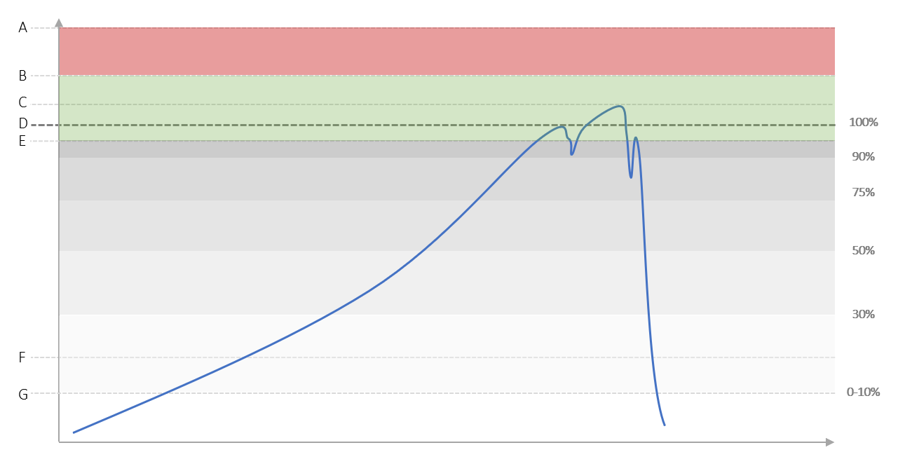
A | Change screw | E | Minimum Torque |
B | Maximum Torque | F | Trigger torque |
C | Final Torque | G | Tightening Program Start |
D | Click Torque |
A result is OK if the Click Torque is within the upper and lower torque limit values defined for the selected tightening program.
For more information on how to configure tightening programs, refer to Power Focus 6000 User Guide or to Power Focus 8 User Guide according to the controller in use.
Torque Control / Angle Monitor Strategy
The Torque Control / Angle Monitor Strategy helps the operator achieve the desired target torque while monitoring the angle.
The main parameters that define this strategy are the following:
Parameter | Description |
|---|---|
Tightening Program start | Torque value from which the tightening operation starts. |
Minimum Torque | Lower torque limit value. |
Maximum Torque | Higher torque limit value. |
Click torque* | Torque target value. |
Trigger torque | Torque value from which the angle measurement starts. |
Minimum Angle* | Lower angle limit value. |
Maximum Angle* | Higher angle limit value. |
Parameters with an asterisk are mandatory.
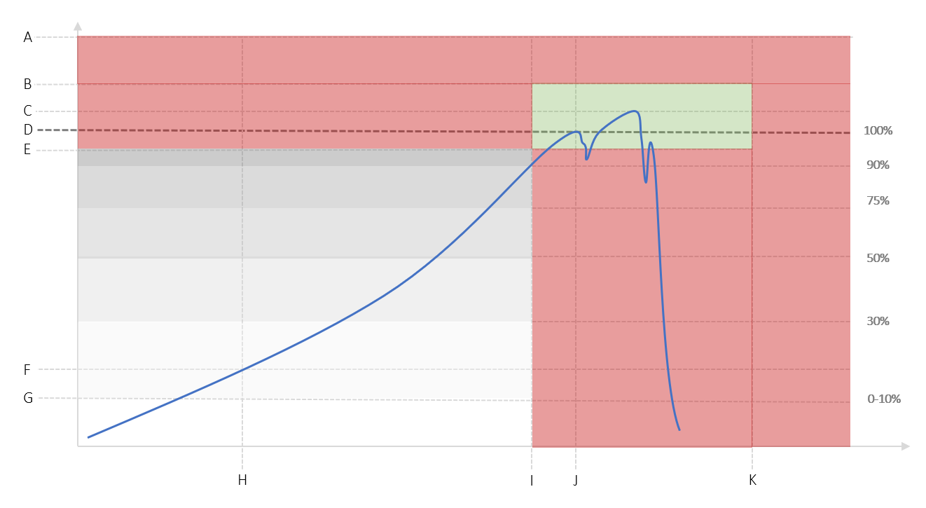
A | Change screw | G | Tightening Program start |
B | Maximum torque | H | Angle measurement start (at Trigger Torque) |
C | Final torque | I | Minimum Angle |
D | Click Torque | J | Angle at Click Point |
E | Minimum Torque | K | Maximum Angle |
F | Trigger Torque |
A result is OK if:
the Click Torque is within the upper and lower torque limit values defined for the selected tightening program,
and
the Angle at Click Point is within the upper and lower angle limit values defined for the selected tightening program.
For more information on how to configure tightening programs, refer to Power Focus 6000 User Guide or to Power Focus 8 User Guide according to the controller in use.
Operating Instructions
Ergonomic Guidelines
Consider your workstation as you read through this list of general ergonomic guidelines to identify areas for improvement in posture, component placement, or work environment.
Take frequent breaks and change work positions frequently.
Adapt the workstation area to your needs and the work task.
Adjust for a convenient reach range by determining where parts and tools need to be located to avoid static load.
Use workstation equipment such as tables and chairs appropriate for the work task.
Avoid work positions above shoulder level or with static holding during assembly operations.
When working above shoulder level, reduce the load on the static muscles by lowering the weight of the tool, using for example torque arms, hose reels or weight balancers. You can also reduce the load on the static muscles by holding the tool close to the body.
Take frequent breaks.
Avoid extreme arm or wrist postures, particularly during operations requiring a degree of force.
Adjust for a convenient field of vision that requires minimal eye and head movements.
Use appropriate lighting for the work task.
Select the appropriate tool for the work task.
In noisy environments, use ear protection equipment.
Use high-quality inserted tools and consumables to minimize exposure to excessive levels of vibration.
Minimize exposure to reaction forces.
When cutting:
A cut-off wheel can get stuck if the cut-off wheel is bent or not guided properly. Always use the correct flange for the cut-off wheel and avoid bending the cut-off wheel during operation.
When drilling:
The drill might stall when the drill bit breaks through. Use support handles if the stall torque is high. The safety standard ISO11148 part 3 recommends using a device to absorb a reaction torque above 10 Nm for pistol grip tools and 4 Nm for straight tools.
When using direct-driven screwdrivers or nutrunners:
Reaction forces depend on the tool settings and joint characteristics. Strength and posture determine the amount of reaction force that an operator can tolerate. Adapt the torque setting to the operator's strength and posture and use a torque arm or reaction bar if the torque is too high.
In dusty environments, use a dust extraction system or wear a mouth protection mask.
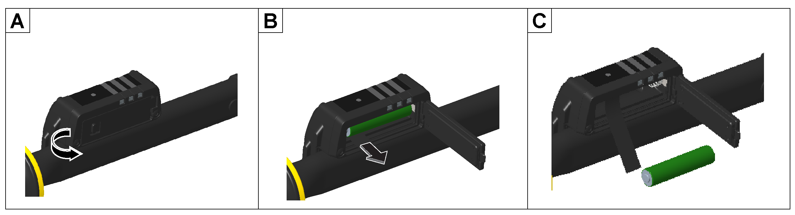
Turning On the Wrench
On the back of the MTRwrench 85 HMI, pull back the locking lever on the battery housing's door and open the door.
Insert the battery into its housing.
Make sure that the lace edge is visible to make removal easier.
Close the battery housing door.
Make sure that the edge of the lace remains inside.

Once the MTRwrench 85 is on, the Progress LEDs on the HMI start blinking with white light  show that a MTRwrench 85 requires a zerozero adjustment is required.
The Radio Communication LED on the HMI starts blinking  to notify the MTRwrench 85 wireless communication is ON.
Turning Off the Wrench
On the back of the MTRwrench 85 HMI, pull back the locking lever on the battery housing door and open the door.
Remove the battery from its housing by pulling the edge of the lace.
Close the battery housing door.
Make sure that the edge of the lace remains inside.
Performing a Zero Adjustment
A zero adjustment is required in the following situations:
After turning on the MTRwrench 85.
After a minor overload of the transducer.
To perform a zero adjustment, proceed as follows:
Place the MTRwrench 85 into the cradle.
Release the wrench and do not touch it again until the zero adjustment is complete.
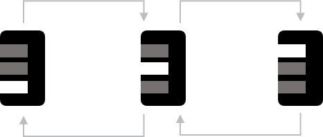
During the zero adjustment, the Progress LEDs turn on and off in sequence as shown in the picture below:
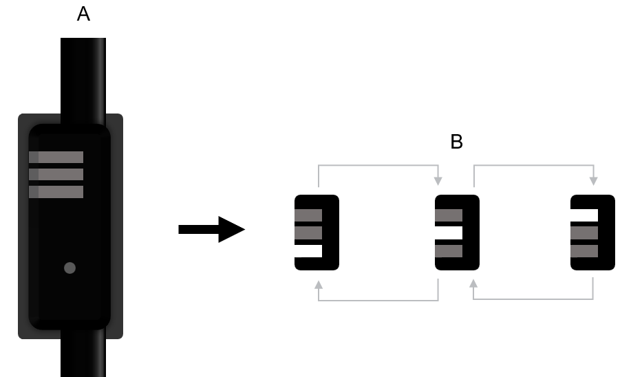
A
Top view of the wrench inside the cradle.
B
Representation of the Progress LEDs behavior during the zero adjustment.
If the zero adjustment is successful, the Progress LEDs turn off.
Handling the Wrench
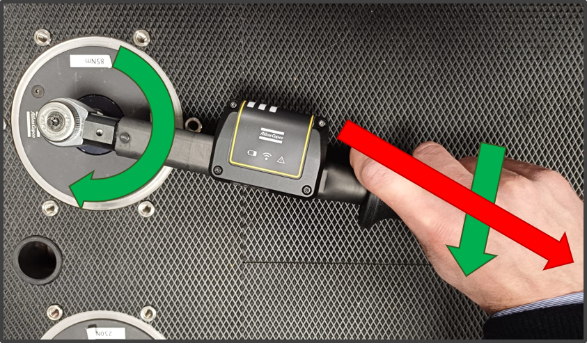
Correct handling:
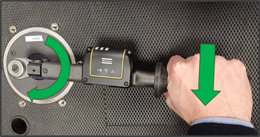
Tighten in even strokes.
Hold the MTRwrench 85 by the middle of the handle when performing a tightening.
Apply force only in the tightening direction.
The force applied to the wrench must be one-handed, uniform, parallel and continue until the tool clicks.
Keep a tightening speed that enables you to immediately stop tightening as soon as the MTRwrench 85 clicks.
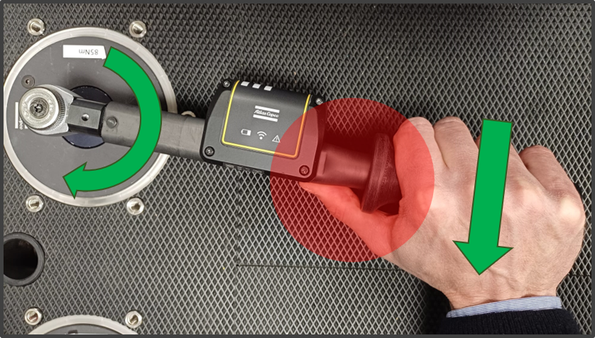
Wrong handling:
Do not apply any force to the wrench after the automatic release (click).
Do not apply force to the wrench in any direction other than the tightening direction.
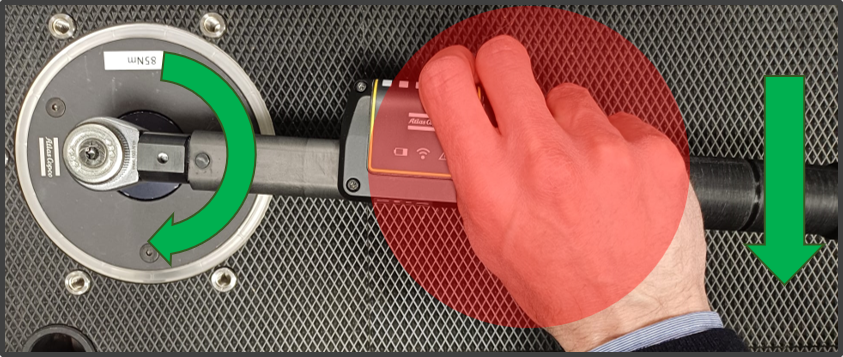
Do not touch the body of the MTRwrench 85 during tightening operations. Positioning the thumb on the tube alters the click value!
Do not hold the battery housing of the MTRwrench 85 during tightening operations.
Running Tightening Operations
Connect the MTRwrench 85 to the Power Focus 6000/Power Focus 8 via MWR-KIT.
On the Power Focus, configure a tightening program and assign the task to the MTRwrench 85.
When the MTRwrench 85 receives the task and the wrench is ready for use, the Job Ready LED on the HMI turns on
 .
.Attach the required end-fitting tool to the wrench and perform the tightening.
The Job Ready LED turns off when the tightening is in progress.
As soon as the MTRwrench 85 reaches the click-point, release the wrench.
The MTRwrench 85 can store up to 10000 results. If the wrench is turned off, or if it goes out of radio range, the results can be retrieved by the Power Focus once the MTRwrench 85 is on again, or when it is back within radio range.
Service
Maintenance Instructions
Service Recommendations
Preventive maintenance is recommended at regular intervals. See the detailed information on preventive maintenance. If the product is not working properly, take it out of service and inspect it.
If no detailed information about preventive maintenance is included, follow these general guidelines:
Clean appropriate parts accurately
Replace any defective or worn parts
Cleaning
Keep the MTRwrench 85 clean.
After use, remove any traces of oil and grease from the MTRwrench 85 with a soft cloth and a soft surface cleaner for oil/grease. Do not use aggressive or abrasive cleaner.
Use an anti-static cleaning cloth in order to remove dust from the MTRwrench 85.
Avoid using harsh detergents to clean the MTRwrench 85.
Clean the contact of the MTRwrench 85 by using an electrical contact cleaner solution.
Recycling
Environmental Regulations
When a product has served its purpose it has to be recycled properly. Dismantle the product and recycle the components in accordance with local legislation.
Batteries shall be taken care of by your national battery recovery organization.
Recycling Instructions
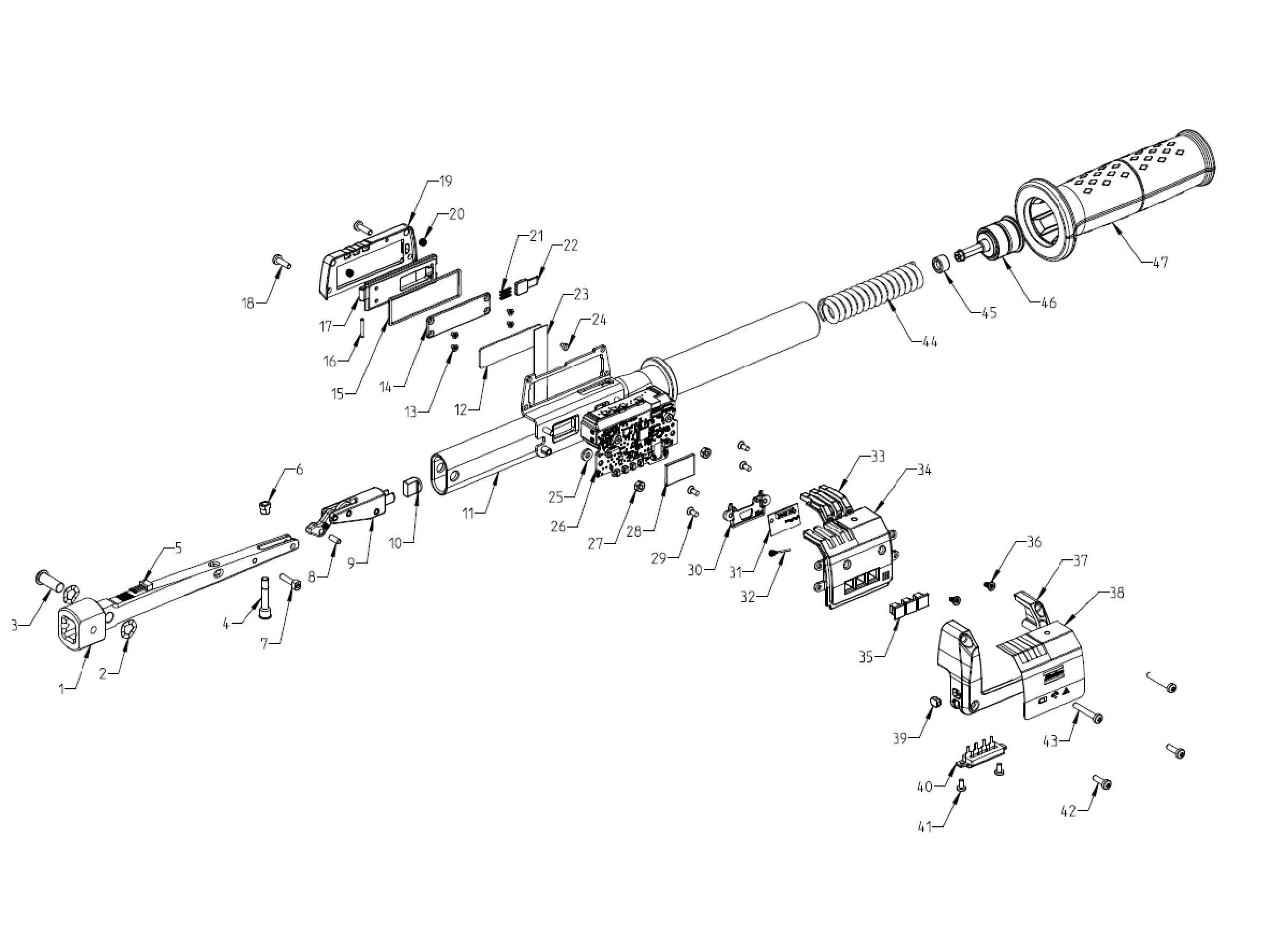
Pos. | Part | Recycle as |
|---|---|---|
1 | Transducer | Mixed waste |
2 | Washer | Copper |
3 | Pin | Steel |
4 | Pin | Steel |
5 | Cable | WEEE |
6 | Nut | Steel |
7 | Screw | Steel |
8 | Pin | Steel |
9 | Kinematic Chain | Steel |
10 | Spacer | Plastic |
11 | Tube | Steel |
12 | Tape | Steel |
13 | Screw | Steel |
14 | Panel | Steel |
15 | Gasket | Rubber |
16 | Pin | Steel |
17 | Door | Steel |
18 | Screw | Steel |
19 | Cover | Aluminum |
20 | Helicoil | Steel |
21 | Spring | Steel |
22 | Button | Steel |
23 | Tape | Plastic |
24 | Screw | Steel |
25 | Spacer | Steel |
26 | Electronic Board 1 | Mixed Waste |
27 | Washer | Steel |
28 | Shield | Steel |
29 | Screw | Steel |
30 | Electronic Support | Plastic |
31 | Electronic Board 2 | WEEE |
32 | Cable | WEEE |
33 | Light Guide | Plastic |
34 | Cover | Plastic |
35 | Light Guide | Plastic |
36 | Screw | Steel |
37 | Cover | Aluminum |
38 | Lable | Plastic |
39 | Light Guide | Plastic |
40 | Connector | WEEE |
41 | Screw | Steel |
42 | Screw | Steel |
43 | Screw | Steel |
44 | Spring | Steel |
45 | Spacer | Plastic |
46 | Regulation System | Steel |
47 | Handle | Plastic |