Product Information
General Information
Symbols on the Tool
The symbols on the tool have the following meanings:
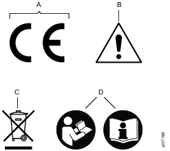
A | Directive 2006/42/EC on Machinery specifies the essential health and safety requirements the product has to meet in order for the manufacturer to affix the CE marking. |
B | When operating the device be sure to use caution. |
C | The symbol indicates that parts within the product must be handled in accordance with the WEEE Directive. |
D | Read the instruction manual/booklet before starting work or before operating equipment or machinery. |
Safety Signal Words
The safety signal words Danger, Warning, Caution, and Notice have the following meanings:
DANGER | DANGER indicates a hazardous situation which, if not avoided, will result in death or serious injury. |
WARNING | WARNING indicates a hazardous situation which, if not avoided, could result in death or serious injury. |
CAUTION | CAUTION, used with the safety alert symbol, indicates a hazardous situation which, if not avoided, could result in minor or moderate injury. |
NOTICE | NOTICE is used to address practices not related to personal injury. |
Warranty
Product warranty will expire 12 months after the product is first taken into use, but will in any case expire at the latest 13 months after delivery.
Normal wear and tear on parts is not included within the warranty.
Normal wear and tear is that which requires a part change or other adjustment/overhaul during standard tools maintenance typical for that period (expressed in time, operation hours or otherwise).
The product warranty relies on the correct use, maintenance, and repair of the tool and its component parts.
Damage to parts that occurs as a result of inadequate maintenance or performed by parties other than Atlas Copco or their Certified Service Partners during the warranty period is not covered by the warranty.
To avoid damage or destruction of tool parts, service the tool according to the recommended maintenance schedules and follow the correct instructions.
Warranty repairs are only performed in Atlas Copco workshops or by Certified Service Partners.
Atlas Copco offers extended warranty and state of the art preventive maintenance through its ToolCover contracts. For further information contact your local Service representative.
For electrical motors:
Warranty will only apply when the electric motor has not been opened.
ServAid
ServAid is a portal that is continuously updated and contains Technical Information, such as:
Regulatory and Safety Information
Technical Data
Installation, Operation and Service Instructions
Spare Parts Lists
Accessories
Dimensional Drawings
Please visit: https://servaid.atlascopco.com.
For further Technical Information, please contact your local Atlas Copco representative.
Safety Data Sheets MSDS/SDS
The Safety Data Sheets describe the chemical products sold by Atlas Copco.
Please consult the Atlas Copco website for more information www.atlascopco.com/sds.
Product Safety Video for Nutrunners
Learn more about safety features on Atlas Copco nutrunners and what measures the operator has to take for a safe operation. Click the link or scan the QR code below to view the video:
https://www.youtube.com/watch?v=FAh6yttvUpw

Signs and Stickers
The product is fitted with signs and stickers containing important information about personal safety and product maintenance. The signs and stickers shall always be easy to read. New signs and stickers can be ordered by using the spare parts list.

Country of Origin
For the Country of Origin, please refer to the information on the product label.
Dimensional Drawings
Dimensional Drawings can be found either in the Dimensional Drawings Archive, or on ServAid.
Please visit: http://webbox.atlascopco.com/webbox/dimdrw or https://servaid.atlascopco.com.
Overview
The Tensor System
The Tensor system consists of a range of tightening tools powered by brushless electric motors and different drive units.
Motors are available in different sizes. All tools are protected from overheating of the motor. Electrical protection system is based on an earth fault circuit brake, Earth Fault Protector (EFP). The EFP senses small current leakage (>30mA) and if leakage occurs, the drive is switched off (30ms). Changing, interfering or tampering with the protection system voids all warranty and obligations from Atlas Copco. Trouble-shooting and re-start of the system may only be carried out by an authorized person. Check the function of the EFP on a regular basis by pressing the trip-button. The EFP should switch off accordingly.
Technical Product Data
Technical Product Data can be found on either ServAid, or the Atlas Copco website.
Please visit: https://servaid.atlascopco.com or www.atlascopco.com.
Service Overview
Service Recommendations
Preventive maintenance is recommended at regular intervals. See the detailed information on preventive maintenance. If the product is not working properly, take it out of service and inspect it.
If no detailed information about preventive maintenance is included, follow these general guidelines:
Clean appropriate parts accurately
Replace any defective or worn parts
Installation
Installation Requirements
Connecting the Tool
The tool should, via its correct Power Focus drive unit, be connected to the mains, 230V/50Hz alternatively 115V/ 60Hz, single phase. See instructions for your Power Focus drive unit.
Grounding
If the tool is mounted in a handheld or hand guided fixture, the fixture should be connected to the drive using a separate 2.5mm2 grounding cable.
Reaction bar
Adapt and use the torque reaction bar as follows:
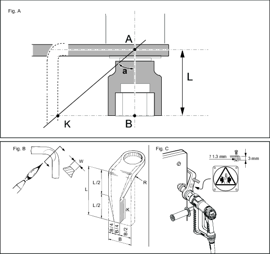
1 Shaping the reaction bar, Fig. A
The torque reaction bar must be shaped to fit a suitable fixed support. The point of contact for the reaction bar depends on the target torque for the tightening and the length of the socket.
Determine the minimum angle a according to the table below.
To avoid overloading of the bearings for the tool drive and of the reaction bar, the point of contact on the reaction bar (K) must be as far away from the tool centre line as possible, see Fig. A.
Torque (Nm) | 200 | 300 | 500 | 750 | 1000 | 1500 | 2000 | 3000 | 4000 |
Angle a (degree) | 46 | 59 | 50 | 45 | 55 | 38 | 41 | 40 | 50 |
2 Defining the bending point of the reaction bar, Fig. A
Use a piece of paper to make the drawing and measurements. Use a ruler and a protractor for accurate drawings.
Determine the minimum angle a, according to the table.
Determine the contact point (K) of the reaction bar. Make it as far away from the tool centre line as possible.
Measure the resulting angle a, and make sure it is greater than the table entry for the selected torque.
3 Bending, Fig. B
Heat the spot to red colour.
It is recommended to concentrate the heat to the inside radius in order not to reduce the original width (W), see fig. B.
-
After bending, allow to cool slightly in room temperature and then chill.
After bending, attach the accompanying warning sign to the reaction bar, see fig. C, and mark the side of the reaction bar that should be placed against the support in a suitable way.
4 Assembly
Place the reaction bar in the wanted position on the machine.
Tighten the nut to a torque of 70 Nm, 90 Nm or 100 Nm respectively.
Check regularly that the lock ring is firmly secured.
5 Use
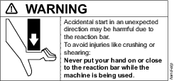
Apply the reaction bar according to figure 4 – opposite the direction of the drive of the machine – before starting the machine.
Never put your hand on or close to the reaction bar while the machine is being used.
Installation Instructions
Fitting of the Tool Cable
-
Make sure that the tool cable is of correct type.
-
Align the cable connector using the two asymmetrically positioned heads on the connector to fit in the slots in the tool handle.
-
Tighten the lock nut.
-
Make sure that the connection is correct by pulling, pushing and turning the cable connector (there should be no movement).
The tool has a built in electronic memory chip that will transmit the torque transducer calibration value and angle pulses to the POWER FOCUS/drive unit. Any changes made of these values in the POWER FOCUS while the tool is connected will be stored in the tool memory.
Operation
Ergonomic Guidelines
Consider your workstation as you read through this list of general ergonomic guidelines to identify areas for improvement in posture, component placement, or work environment.
Take frequent breaks and change work positions frequently.
Adapt the workstation area to your needs and the work task.
Adjust for a convenient reach range by determining where parts and tools need to be located to avoid static load.
Use workstation equipment such as tables and chairs appropriate for the work task.
Avoid work positions above shoulder level or with static holding during assembly operations.
When working above shoulder level, reduce the load on the static muscles by lowering the weight of the tool, using for example torque arms, hose reels or weight balancers. You can also reduce the load on the static muscles by holding the tool close to the body.
Take frequent breaks.
Avoid extreme arm or wrist postures, particularly during operations requiring a degree of force.
Adjust for a convenient field of vision that requires minimal eye and head movements.
Use appropriate lighting for the work task.
Select the appropriate tool for the work task.
In noisy environments, use ear protection equipment.
Use high-quality inserted tools and consumables to minimize exposure to excessive levels of vibration.
Minimize exposure to reaction forces.
When cutting:
A cut-off wheel can get stuck if the cut-off wheel is bent or not guided properly. Use the correct flange for the cut-off wheel and avoid bending the cut-off wheel during operation.
When drilling:
The drill might stall when the drill bit breaks through. Use support handles if the stall torque is high. The safety standard ISO11148 part 3 recommends using a device to absorb a reaction torque above 10 Nm for pistol grip tools and 4 Nm for straight tools.
When using direct-driven screwdrivers or nutrunners:
Reaction forces depend on the tool settings and joint characteristics. Strength and posture determine the amount of reaction force that an operator can tolerate. Adapt the torque setting to the operator's strength and posture and use a torque arm or reaction bar if the torque is too high.
In dusty environments, use a dust extraction system or wear a mouth protection mask.
Operating Instructions
General instructions
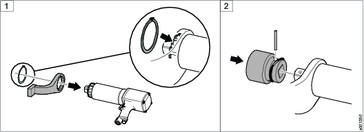
The tool may only be used together with the associated torque reaction bar, which is adapted to the screw joint application concerned.
Attach the reaction bar to the tool and insert the retaining ring into the groove to hold the reaction bar in position.
Attach the socket to the square drive. Insert the locking pin through the socket and square drive according to the illustration.


Operating
Make sure that the tool is in correct working order and that the controller is correctly programmed to avoid unexpected behaviour from the tool, which may result in operator injury.
Check that the tool is in the correct running direction by looking at the function light situated above the tool handle, by turning the reverse ring (only for ETV/ETD DS or by turning the arm on the trigger knob (only for ETP DS).
The soft-start function facilitates entering the screw head and thread.
The duration of the soft start is adjustable, see the manual for the drive unit.
The tool is equipped with signal lights,
Green = OK tightening
Yellow = Warning – low torque (not for ES)
Red = Warning – high torque
Orange = Function indicator (only for SL and DL)
Blue = Function indicator (only for SL)
Service
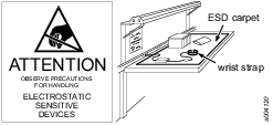
Preventing ESD Problems
The components inside the product and controller are sensitive to electrostatic discharge. To avoid future malfunction, make sure that service and maintenance is carried out in an ESD approved work environment. The figure below shows an example of an appropriate service work station.
Maintenance Instructions
Overhaul
Service must only be carried out by qualified personnel who have access to the Service instruction and/or have been trained for service on Tensor tools.
The electric motor is a sealed unit and may under no circumstances be opened by anyone else than Atlas Copco Industrial Technique AB!
If you decide that the electric motor is defect or in need of service, return the complete motor unit to Atlas Copco Industrial Technique for replacement.
Motors which have been opened by anyone else than Atlas Copco Industrial Technique will not be serviced.
Overhaul and preventive maintenance is recommended at regular intervals once per year or after maximum 250.000 tightening depending on which occurs sooner. More frequent overhaul may be needed if the machine is used in heavy-duty operations. If the machine not is working properly, it should immediately be taken away for inspection.
When dismantling the tool always use the specially designed service tool 4080 0848 80, (two service tools are required).
Service Recommendations
Preventive maintenance is recommended at regular intervals. See the detailed information on preventive maintenance. If the product is not working properly, take it out of service and inspect it.
If no detailed information about preventive maintenance is included, follow these general guidelines:
Clean appropriate parts accurately
Replace any defective or worn parts
Service instructions
Overhaul and preventive maintenance is recommended at regular intervals once per year or after maximum 250.000 tightening depending on which occurs sooner. More frequent overhaul may be needed if used at high torque, high cycle rate or long tightening times. If the machine is not working properly, it should immediately be taken away for inspection.
At the overhauls, all parts should be cleaned accurately and defective or worn parts (i.e. O-rings) should be replaced.
Lubrication Instructions
Lubricating Guide
Brand | Cable nut | Front Gear | General purpose | Internal gear |
|---|---|---|---|---|
Molycote | - | BR2 Plus | - | - |
CRC | Litium grease No. 3020 | - | - | - |
Almagard | - | - | LE 3751 | - |
Rhenus | - | - | - | LKR 03 |
Lubrication
Planetary gears, needle bearings and ball bearings must be lubricated with soft grease containing molybdenumdisulphide at the regular overhaul of the tool.
Repair Instructions
Repair
Repair must only be carried out by qualified authorised personnel. For further information contact your local Atlas Copco sales representative.
Troubleshooting
If the Tool Becomes Very Hot
With proper adjustment the tool can handle any normal line jobs that an operator sustains. What can cause overheating are combinations of some factors: torque above rated, too low speed, too long ramp time (motor has to give high torque for a long time), very high prevailing torque, very soft joints, short cycle time. To correct, look over speed, ramp time, tightening strategy. One stage and Ergoramp are most heat conserving when applicable. Please refer to the User Guide of your POWER FOCUS. If the above corrections are not enough, choose a tool of the next higher capacity.
Power Focus 3000/4000
Is the POWER FOCUS switched on and in RUN mode? Check that the correct POWER FOCUS is used (ST31/ST32/ST61/STR31/STR61-Tensor3-7, ST81-Tensor8-9). Check the fuses for the drive part. Check Drive parameters, refer to the User Guide of the POWER FOCUS/ drive unit. Check the earth fault circuit breaker on the backside of the drive. Should it have tripped, make sure to find the primary fault before resuming operation. Check that the wiring on the remote start connector is correct. For further information see 9836 2258.
Power Focus 600/6000
Is the unit switched on? Check the earth fault circuit breaker behind the front door. Should it have tripped, make sure to find the primary fault before resuming operation. Check that the wiring on the remote start connector is correct. For further information see 9836 4954/9836 7446.
Recycling
Environmental Regulations
When a product has served its purpose it has to be recycled properly. Dismantle the product and recycle the components in accordance with local legislation.
Batteries shall be taken care of by your national battery recovery organization.
Recycling information Tensor ST101
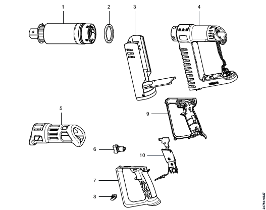
Part | Remarks | Recycle as | |
1 | Gear unit |
| Metal, Steel |
2 | Spacer |
| Plastics, Other, POM |
3 | Fan, complete |
| Electronic |
4 | Motor casing |
| Electronic |
5 | Protective cover |
| Plastics, PP |
6 | Trigger button |
| Metal, Steel |
7 | Handle |
| Plastics, Other, PA |
8 | Reverse button |
| Metal, Brass |
9 | Handle |
| Plastics, Other, PA |
10 | Main card |
| Electronic |