Product Information
General Information
Safety Signal Words
The safety signal words Danger, Warning, Caution, and Notice have the following meanings:
DANGER | DANGER indicates a hazardous situation which, if not avoided, will result in death or serious injury. |
WARNING | WARNING indicates a hazardous situation which, if not avoided, could result in death or serious injury. |
CAUTION | CAUTION, used with the safety alert symbol, indicates a hazardous situation which, if not avoided, could result in minor or moderate injury. |
NOTICE | NOTICE is used to address practices not related to personal injury. |
Warranty
Product warranty will expire 12 months after the product is first taken into use, but will in any case expire at the latest 13 months after delivery.
Normal wear and tear on parts is not included within the warranty.
Normal wear and tear is that which requires a part change or other adjustment/overhaul during standard tools maintenance typical for that period (expressed in time, operation hours or otherwise).
The product warranty relies on the correct use, maintenance, and repair of the tool and its component parts.
Damage to parts that occurs as a result of inadequate maintenance or performed by parties other than Atlas Copco or their Certified Service Partners during the warranty period is not covered by the warranty.
To avoid damage or destruction of pump parts, service the pump according to the recommended maintenance schedules and follow the correct instructions.
Warranty repairs are only performed in Atlas Copco workshops or by Certified Service Partners.
For electrical motors:
Warranty will only apply when the electric motor has not been opened.
Website
Information concerning our Products, Accessories, Spare Parts and Published Matters can be found on the Atlas Copco website.
Please visit: www.atlascopco.com.
ServAid
ServAid is a portal that is continuously updated and contains Technical Information, such as:
Regulatory and Safety Information
Technical Data
Installation, Operation and Service Instructions
Spare Parts Lists
Accessories
Dimensional Drawings
Please visit: https://servaid.atlascopco.com.
For further Technical Information, please contact your local Atlas Copco representative.
Safety Data Sheets MSDS/SDS
The Safety Data Sheets describe the chemical products sold by Atlas Copco.
Please consult the Atlas Copco website for more information www.atlascopco.com/sds.
Country of Origin
For the Country of Origin, please refer to the information on the product label.
Dimensional Drawings
Dimensional Drawings can be found either in the Dimensional Drawings Archive, or on ServAid.
Please visit: http://webbox.atlascopco.com/webbox/dimdrw or https://servaid.atlascopco.com.
Overview
Intended Use
This device is exclusively intended for professional use as a drive mechanism for hydraulic torque tools in line with the description given in these product information.
Any other use is considered to be improper
In particular , the use of the machine as a drive for all other pump units such as presses, hoisting cylinders, hydraulic shears, spreaders, etc. is improper use.
Improper use of the device or modifications to the device undertaken by the end-user exclude any liability on the part of the manufacturer and invalidate the declaration of conformity.
In this case the user is liable for damages resulting from the use of the device.
Residual risks
Danger due to noise: maximum noise level 82 dB(A); the end-user must make personal protective equipment (ear-protectors) available.
Technical Product Data
Technical Product Data can be found on either ServAid, or the Atlas Copco website.
Please visit: https://servaid.atlascopco.com or www.atlascopco.com.
Service Overview
Service Recommendations
Preventive maintenance is recommended at regular intervals. See the detailed information on preventive maintenance. If the product is not working properly, take it out of service and inspect it.
If no detailed information about preventive maintenance is included, follow these general guidelines:
Clean appropriate parts accurately
Replace any defective or worn parts
Installation
Installation Instructions
Use and Conditions for Storage
Ambient temperature: -10 to +40°C for use and storage.
Protect from rain during use and storage.
Contact Atlas Copco in the event of change in working conditions or use of this product.
Power supply connections: In the event of modification to the mains connection, protection against shock must be guaranteed by installing a protective earth system.(delivery with earthed pin plug).
Initial Configuration
Before Initial Operation
Carry out a visual inspection before each start-up.
Check remote control, mains plug and all cables for damage.
Check hose couplings, hoses and hydraulic torque tools for damage.
Hoses and hydraulic torque tools are not included in delivery.
Hose couplings, hoses and hydraulic torque tools must be designed for an operating pressure of Max.700 bar / 10,000 PSI..
Hose couplings, hoses and hydraulic torque tools with lower operating pressures are not permitted to be connected to the pump unit.
Check the entire machine, fluid reservoir, motor, manometer and air line lubricator for damage such as ruptures or leaks.
Have damaged parts replaced by qualified technicians before operation.
Check hose couplings for dirt.
Clean soiled hose couplings before operation.
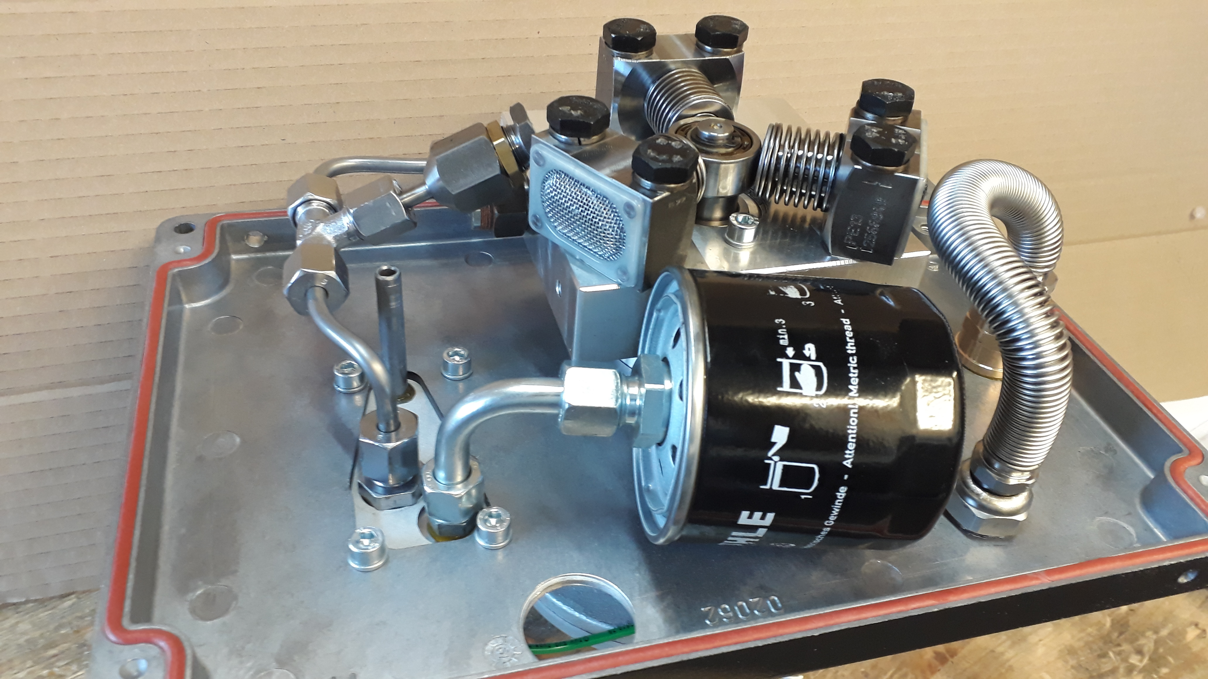
Check the fluid level; the level must be up to the middle of the oil sight glass; top up hydraulic fluid, if needed. Use recommended grade of oil as per chart see also,Hydraulic Fluid
Set up the pump unit on a level, horizontal surface so that it is prevented from falling over or falling down.
Connect the pump unit by means of the threaded couplings with the hoses and with the hydraulic torque tool.

Refer below picture to check section,
Connect the pump unit to the air supply.
Ensure a dynamic pressure of 5-6 bar and air volume of minimum 40 cfm is available. Higher pressures can lead to excessive wear and tear or damage the seals / valves.
The pump unit must not be operated without the hoses and the hydraulic torque tool connected up.
Operation
Ergonomic Guidelines
Consider your workstation as you read through this list of general ergonomic guidelines to identify areas for improvement in posture, component placement, or work environment.
Take frequent breaks and change work positions frequently.
Adapt the workstation area to your needs and the work task.
Adjust for a convenient reach range by determining where parts and tools need to be located to avoid static load.
Use workstation equipment such as tables and chairs appropriate for the work task.
Avoid work positions above shoulder level or with static holding during assembly operations.
When working above shoulder level, reduce the load on the static muscles by lowering the weight of the tool, using for example torque arms, hose reels or weight balancers. You can also reduce the load on the static muscles by holding the tool close to the body.
Take frequent breaks.
Avoid extreme arm or wrist postures, particularly during operations requiring a degree of force.
Adjust for a convenient field of vision that requires minimal eye and head movements.
Use appropriate lighting for the work task.
Select the appropriate tool for the work task.
In noisy environments, use ear protection equipment.
Use high-quality inserted tools and consumables to minimize exposure to excessive levels of vibration.
Operating Instructions
Operating the Machine
Switch on the motor by actuating the white push-button on the remote control.

Button with "I" starts and one with "0" stops the pump.

Switch off the motor by actuating the push-button with "0"on the remote control.
Relieve pressure of the device by manually actuating the solenoid valve.
Pressure and / or Torque Adjustment
The torque of hydraulic torque wrenches is proportional to the pressure. This is why before tightening or loosening bolted connections the maximum pressure of the machine and thus the maximum torque of the torque tool must be adjusted.
Do not place the hydraulic tool on either bolts or nuts.
Switch on the motor by pushing the I-button on the remote control and keep the I push-button pressed down – the tool piston extends.
After reaching the end position of the tool piston, the maximum pressure of the system can be increased by turning the adjustment knob (a) on the pressure adjustment valve (b) clockwise until the required pressure is reached. The current system pressure is displayed on the manometer.

By releasing the I push-button, the tool piston retracts.
Checking the setting: after reaching the end position a second time, press the I push-button again in order to extend the tool piston completely and to keep it until the maximum pressure is reached.
Bring it below the desired pressure mark and turn the adjustment knob (a) on the pressure adjustment valve (b) clockwise again to reach the required pressure point.
When the required pressure is reached, the setting is secured by tightening the wing nut (c) on the pressure adjustment valve (b).
Please check torque pressure chart of each tool carefully for setting the pressure. Different size tools will deliver different torque at same pressure.
Tightening or loosening threaded connections
Please check manual of hydraulic torque wrenches for bolt tightening and loosening operation.
Operating Hydraulic Pump
Setting Working Pressure on the Pump
To set the pressure on the pump, follow this procedure:
Loosen the knurled locking ring below the "T" handle on the pump's external pressure regulator. Then turn the "T" handle counter clockwise (CCW) until it turns freely and easily.
Turn the pump "on". Using the pump's remote control pendant, push down the advance switch (or button on air pumps) and hold it.
While holding the pump in the advance mode, slowly turn the "T" handle clockwise and observe the pump pressure gauge rise.
Always adjust the regulator in order to increase the pressure up - Never down. Never adjust the regulation with the tool on the application
When your gauge reaches 4,000 PSI stop turning the "T" handle and let the gauge settle out.
If the pressure continues to rise (above 4,000), release the advance button and back off your pressure slightly-by turning CCW on the "T" handle. Then re-depress the advance switch on you remote and slowly bring pressure up to 4,000 again.
When the pressure is correct, turn the pump "off" and tighten the knurled lock nut provided under the "T" handle. This sets pump pressure, which determines torque tool output.

Once your target pressure is set and locked, cycle the pump once more to ensure that your pressure setting did not change as you turned down the knurled knob.
Applying Torque to Wrench
Having set your target pressure, cycle the tool three or four times to full pressure. Cycling the tool ensures that the system is operating properly and removes trapped air, if any.
Verify that any impact sockets used are rated to accept the full torque output of the tool they are to be used with. Ensure the correct size impact socket for the nut A/F has been selected, placed on the square drive and secure with a locking pin and ring.
Place the tool and the socket on the nut, making sure that the socket has fully engaged the nut, check that the drive retainer is engaged.
Make sure the reaction arm is firmly abutted against a stationary object (i.e. an adjacent nut, flange, equipment housing etc.). When positioning the wrench, make sure that the hose connections are well clear of any obstructions and that all body parts are safely out of harm's way. Then apply momentary pressure to the system to ensure proper tool placement. If it doesn't look or act right, stop and re-adjust the reaction arm.
Read Safety Instructions supplied with the torque wrench for further guidance on tool usage
By pushing down on the remote control button in the advance position, the rear of the tool will be pushed back until its reaction arm will contact its reaction point.
Continue to hold down the button as the socket turns until you hear an audible "click" which will signify the hydraulic cylinder inside the tool is fully extended and will not turn the advance further.
Continuing to hold down the remote control button will result in a rapid build up of pressure to the point of where the gauge reads what was preset prior to applying the wrench.
The reading of full preset pressure after the cylinder is extended DOES NOT INDICATE that this pressure (torque) is applied to the bolt. It only indicates that the cylinder is fully extended and cannot turn the socket or the ratchet link further until the tool automatically resets itself.
Releasing the remote control button will retract the cylinder. The tool will automatically reset itself and the operator will hear an audible "click" indicating he can again push the remote control button and the socket will turn. Each time the cylinder is extended and retracted, it is called a cycle. Successive cycles are made until the tool "stalls" at the pre-set Torque/PSI with an accuracy of +/-3%. Repeatability is +/- 1%.
Always attempt one final cycle to ensure the "stall" point has been reached.
Should the tool "lock-on" after the final cycle, push down on the remote control button once more (to build pressure) and, while maintaining this pressure, pull back on the external disengagement lever (RT) or reaction Pawl (RTX). Releasing the remote control while continuing to hold back on the pawl lever/reaction pawl will allow the tool to be removed easily.
Loosening Procedures
First, set the pump to 9,000 PSI (Do not try directly at 10.000 PSI). Change the drive and the reaction arm to the loosening mode (Left = Loose), assuring the reaction arm abuts squarely off a solid reaction point. Press and hold the remote control button down. Pressure will decrease as the socket begins to turn. As the cylinder extends fully, you will hear an audible "click". Release the remote control button, and the cylinder automatically retracts, at this time you will again hear the audible "click". Repeat this process until the fastener can be removed by hand. First, set the pump to 9,000 PSI (Do not try directly at 10.000 PSI). Change the drive and the reaction arm to the loosening mode (Left = Loose), assuring the reaction arm abuts squarely off a solid reaction point. Press and hold the remote control button down. Pressure will decrease as the socket begins to turn. As the cylinder extends fully, you will hear an audible "click". Release the remote control button, and the cylinder automatically retracts, at this time you will again hear the audible "click". Repeat this process until the fastener can be removed by hand.
NOTE : If the bolt does not loosen with the above procedure, it is an indication that you need a larger tool to loosen the bolt.
Setting Torque
All Atlas Copco power packs operate at a pressure range from 500 to 10,000 PSI and are fully adjustable. They have been engineered and designed for portability and high flow for increased speed. Before using your Atlas Copco power pack, check the following points.
Is the reservoir filled with oil?
Where is the closest electrical outlet at the job site?
Is there enough air pressure (60 to 100 PSI) and Air flow at the job site? (Air units only)
Is the gauge mounted and rated for 10,000 PSI/700 bar?
Working Pressure
The pump's maximum working pressure is 10,000 PSI / 700bar. Make sure all hydraulic equipment and accessories are rated for 10,000 PSI / 700bar operating pressure. Hydraulic pumps are available with higher pressure outputs, if not using an Atlas Copco power pack verify maximum operating pressure of the unit being used and ensure the system maximum operating pressure (10,000 PSI / 700 bar) is not exceeded.
Hydraulic Connections
Never disconnect or connect hydraulic hoses or fittings without first unloading the wrench. Unplug the electrical cord of the pump, and open all hydraulic controls several times to assure that the system has been depressurized. If the system includes a gauge, double check the gauge to assure pressure has been released. When making a connection with quick disconnect couplings, make sure the couplings are fully engaged threaded connections such a fittings, gauges etc. must be clean and securely tightened and leak free.
CAUTION - Loose or improperly threaded couplers can be potentially dangerous if pressurized, however, severe over tightening can cause premature thread failure. Fittings need to be only tightened secure and leak free. Never grab, touch or in any way come in contact with a hydraulic pressure leak. Escaping oil can penetrate the skin and cause injury. Do not subject the hose and potential hazard such as sharp surfaces, extreme heat or heavy impact. Do not allow the hose to kink and twist. Inspect the hose for wear before it is used.
Electrical Power
Check the proper electrical supply before connecting.
This motor may spark. Do not operate in an explosive atmosphere or in pressure of conductive liquids.
Do not use a power or extension cord that is damaged or has exposed wiring.
All single phase motors come equipped with a three prong grounding type plus to fit the proper grounded type electrical outlet. Do not use a two prong ungrounded extension cord as the pump's motor must be grounded.
Compare motor nameplate against power availability to prevent motor burnout or dangerous electrical overloading.
Prior to Use
Check hydraulic oil (Use Atlas Copco maximiser range Grade 46) level to prevent possible pump burnout. Open the filler plug located on the reservoir plate. Look at oil fill level on the oil sight gauge. The oil level should be approximately 2" from the top of the reservoir plate- with motor off. Add oil as necessary. Do not mix different grades of oil. Make sure all desired gauge, valve, hose and quick coupler connections are tight and secure before operating. The use of a pressure gauge is required for normal pump operation. Mounted on the manifold, the gauge permits the operator to monitor the load on the wrench. Class1 certified calibrated gauges are available for most applications
Shut down procedure
Release the pressure in the system by pressing and holding down the 0 -button and at the same time pressing the I-button once.
Disconnect the pump unit from the compressed air supply or power mains as may be the case.
Turn the adjustment knob on the pressure adjustment valve all the way anti-clockwise and thus set the maximum pressure to 0 bar.

Disconnect the pump unit from the hoses.
Never use spanner or any external tool to open the hydraulic connections. Ensure all pressure is released by pressing the solenoid valve again if couplings hard to open. Shake the hoses near the couplers while keep trying to unscrew the connections.
Service
General Service Instructions
Electrical work may only be carried out by qualified electricians.
Use only original spare parts as per the spare parts list.
Hydraulic fluid change and filter change (if fitted) at least once every year or at the latest after every 300 operation hours; if necessary earlier, if the pump unit is used in a dusty environment.
Recommended hydraulic fluids: check oil chart.
Hydraulic fluid quantity : see Technical Data
Fluid filter as per spare parts list.
Quick-Disconnects
Fittings should be checked periodically for leaks. Dirt or foreign materials should be kept away from fittings.
Clean before use.
Hydraulic Gauge
Some gauges are liquid filled. Should this liquid level drop, it indicates external leakage, and replacement is necessary.
Should the gauge fill with hydraulic oil, it indicates internal failure and it should be discarded.
Filter on Pump
The filter should be replaced twice a year in normal use and more often if the pump is used daily or in a dirty, harsh environment.
Remote Control
The air line to the remote control unit should be checked for obstructions or kinks in the line periodically. If there is a bend or break in the line, it must be replaced. The spring-loaded buttons on the remote handle should be checked in the event of operating difficulties.
Maintenance Instructions
Oil change intervals
Portable hydraulic equipment are susceptible to contamination due to the extreme conditions in which they work. Although selected fluids are designed to suffer less degradation than another product, we recommend an oil change and filter at least every 750 hours of use, or once a year, whichever occurs first.
It is recommended to periodically check the color of the oil and level seeking extreme contamination or loss of oil level that will require to refill the tank.
For oil changes or refilling, it is always recommended to use the same oil in the pump.
In case of an emergency and having to refill the tank and mix different types of fluids, it is preferred to use fluids with no additives as the HL or HLP fluids. After that, and always before a period of 2-4 working days, replace the oil with recommended oils.
Oil specification
The behavior “In-service” of a hydraulic equipment heavily depends on the quality and characteristics of the hydraulic fluid selected. The choice of the specification and viscosity of the hydraulic fluid should be based of the conditions of use, taking into account several factors as follows:
The range of environmental temperature.
The range of oil viscosity defined for the equipment.
The application (for example: range of pressures, sources of contamination of the hydraulic fluid, the type of pump).
The ease of getting a proper replacement or equivalent hydraulic liquid.
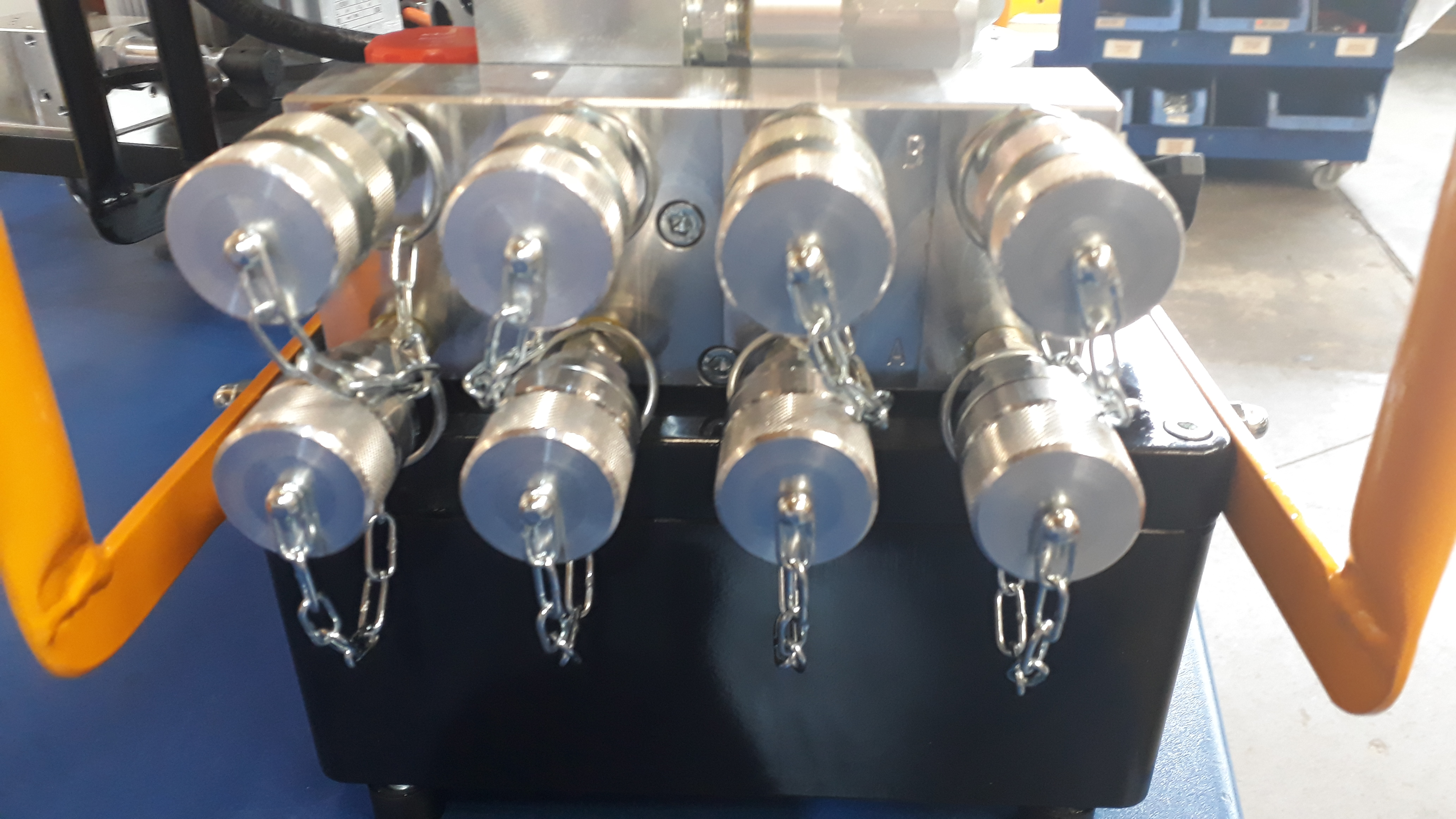
Factory Connections for Couplers and Nipples
Tool
Advance Side - Male
Retract Side - Female
Hose
Advance Side - Female to Female
Retract Side - Male to Male
Pump
Advance Side - Male
Retract Side - Female
Transportation Instructions
Use corrugated cardboard for packing.
Use pallet to lift pump and secure with strapping properly.
Pump should be transported without oil.
Transport of the machine ready for operation:
Please follow local guidelines for weight handling by hand.
With industrial trucks: Use suitable hoisting equipment
Hanging: Use suitable slings (no chains, no metal ropes).

Attachment point for slings
Service Recommendations
Preventive maintenance is recommended at regular intervals. See the detailed information on preventive maintenance. If the product is not working properly, take it out of service and inspect it.
If no detailed information about preventive maintenance is included, follow these general guidelines:
Clean appropriate parts accurately
Replace any defective or worn parts
Lubrication Instructions
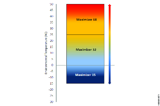
Hydraulic Fluid
The performance of hydraulic equipment is heavily dependent on the quality and characteristics of the hydraulic fluid selected for use. The choice of the specification and viscosity of the hydraulic fluid should be based of the conditions of use, taking into account several factors as follows:
The range of environmental temperature.
The range of oil viscosity defined for the equipment.
The application (range of pressures, sources of contamination of the hydraulic fluid, the type of pump, etc.)
The ease of getting a proper replacement or equivalent hydraulic fluid.
Example: ISO Grade 15, 32 and 68.
For changing or refilling the oil, it is recommended to use the same oil as supplied with the pump.
Hydraulic Oil Selection Chart
Please use the link below to find our safe data sheets for Maximizer.
https://www.atlascopco.com/en-uk/sys/safetydatasheets
Troubleshooting
Troubleshooting Guide
Malfunction | Possible cause | Remedy |
|---|---|---|
Motor does not start | Mains cable not connected | connect Mains cable |
Incorrect mains voltage | Check mains voltage; if necessary connect to suitable electricity supply | |
Mains cable faulty | Have it replaced by qualified electrician | |
Remote control cable faulty | ||
Remote control faulty | ||
Machine faulty | Have it serviced by authorised workshop | |
No (or insufficient) pressure build-up even though motor is running | Too little or no hydraulic fluid | Top up hydraulic fluid |
Maximum pressure not set or set too low | Adjust pressure see also Pressure and / or Torque Adjustment | |
Machine faulty | Have it serviced by authorised workshop | |
Tool does not move even though pressure builds up correctly | One or several hose couplings not tightly connected | Connect up machine, hoses and tool see also Before Initial Operation |
Tool works the wrong way round | Tool connected incorrectly | Connect up machine, hoses and tool see also Before Initial Operation |
Recycling
Environmental Regulations
When a product has served its purpose it has to be recycled properly. Dismantle the product and recycle the components in accordance with local legislation.