Assembly Control Mini PN
Panel PC
Product Information
General Information
Safety Signal Words
The safety signal words Danger, Warning, Caution, and Notice have the following meanings:
DANGER | DANGER indicates a hazardous situation which, if not avoided, will result in death or serious injury. |
WARNING | WARNING indicates a hazardous situation which, if not avoided, could result in death or serious injury. |
CAUTION | CAUTION, used with the safety alert symbol, indicates a hazardous situation which, if not avoided, could result in minor or moderate injury. |
NOTICE | NOTICE is used to address practices not related to personal injury. |
Website
Information concerning our Products, Accessories, Spare Parts and Published Matters can be found on the Atlas Copco website.
Please visit: www.atlascopco.com.
ServAid
ServAid is a portal that is continuously updated and contains Technical Information, such as:
Regulatory and Safety Information
Technical Data
Installation, Operation and Service Instructions
Spare Parts Lists
Accessories
Dimensional Drawings
Please visit: https://servaid.atlascopco.com.
For further Technical Information, please contact your local Atlas Copco representative.
Safety Data Sheets MSDS/SDS
The Safety Data Sheets describe the chemical products sold by Atlas Copco.
Please consult the Atlas Copco website for more information www.atlascopco.com/sds.
Country of Origin
For the Country of Origin, please refer to the information on the product label.
Dimensional Drawings
Dimensional Drawings can be found either in the Dimensional Drawings Archive, or on ServAid.
Please visit: http://webbox.atlascopco.com/webbox/dimdrw or https://servaid.atlascopco.com.
Overview
Applications
The Industrial PC is a computer system which can support several applications, including:
An interface between the factory network and tightening equipment
A platform to operate error proofing systems with PC-based visualization
Technical Data
Assembly Control Mini PN | |
|---|---|
CPU Type | Intel® Celeron J6412 @up to 2.60 GHz |
Mainboard | ECM-EHL3 A1 J6412 Lite |
Mass Storage | 128 GB MLC |
Ports | 2x Ethernet 100Mbit/s D coded M12; 2x USB 2.0 Type A; 1x RS232 A coded M12; 2x Profinet 100Mbit/s D coded M12;, 8x I/O (24 V/up to 200 mA, 300mA total) 2 IN, 4 OUT, +/- 24V A coded M12 |
Display | 10,1": LED TFT, 16:10, 1280 x 800 pixel, brightness typ. 500 cd/m² AUO G101EAN02.2 |
Touch | PCAP |
Ingress Protection | IP54 |
Type of Battery | 8 Li-Mn02 |
Operating System | Windows 10 IoT Enterprise LTSC 2021/H2 (standard) Linux (supported) Windows 11 (supported) |
Weight (Kg) | 3.5 |
Weight (lb) | 7.72 |
Dimensions [L×W×H] (mm) | 48×295.40×213.4 |
Ambient working temperature (°C) | 0°C to 40°C |
Ambient working temperature (°F) | 32°F to 104°F |
External Interfaces
Serial Port | 1×M12 8-pin (male), RS-232 (RS-232/422/485) with waterproof cover and chain |
USB Port | 2×Typ A USB 2.0 with waterproof cover and chain |
LAN Port | 2×M12 4-pin (female) for LAN with waterproof cover and chain |
Power button | 1×Power Switch on the back |
Power Connector | 1×M12 4-pin (male) for +24V DC power with waterproof cover and chain |
Position of the S/N label

Installation
Installation Requirements
Primary Interfaces Connections
Ports and external interfaces are present on the back side of the unit. The units ports can be used to connect the Panel PC to an external device.

1 | Profinet 1 | 5 | Power Button | 9 | GPIO Connector |
2 | Profinet 2 | 6 | USB 1 | 10 | Power Connector |
3 | Ethernet 1 | 7 | USB 2 | ||
4 | Ethernet 2 | 8 | RS-232/422/485 COM |
External I/O Module
GPIO Connector 1x M12 8-pin (female A coded)
GPIO | PIN | Signal Name |
|---|---|---|
| 1 | GND |
2 | Out 1 | |
3 | Out 2 | |
4 | Out 3 | |
5 | Out 4 | |
6 | In 1 | |
7 | In 2 | |
8 | 24V |

1x M12 8-pin (male A coded) RS 232/422/485 COM
(RS-232/422/485 by EMX-APLP)
Serial Port | PIN | RS-232/422/485 |
|---|---|---|
| 1 | DCD / 422R+ |
2 | RXD / 422R- | |
3 | TXD / 422T- / 485- | |
4 | DTR / 422T+ / 485+ | |
5 | GND | |
6 | DSR | |
7 | RTS | |
8 | CTS |
2x M12 4-pin (female D coded) for LAN
2 x M12 4-pin (female) for LAN with waterproof cover and chain
Serial Port | PIN | Pin Define |
|---|---|---|
| 1 | TD+ |
2 | RD+ | |
3 | TD- | |
4 | RD- |

Power Connector
1 x M12 4-pin (male coded A) for DC power with waterproof cover and chain
Serial Port | PIN | Pin Define |
|---|---|---|
| 1 | 24V |
2 | GND | |
3 | GND | |
4 | 24V |

Software Installation Requirements
Installation via any of the following methods is possible:
PXE boot (network)
USB stick
External USB drive
Power Supply Cable
Power Supply Cable 100-240 VAC
The product ships with 1xM12 4-pin (female coded A) 24V DC cable. Additionally, the above mentioned cable can be ordered separately. The order number is 8434230421.
If the unit operates with an external power supply, add the cable type with Part Number: 8434230429 to the box. Use one of the following cable types:
4222 1801 13 | Power cable EU - type E/F |
4222 1802 13 | Power cable US - type B |
4222 1803 13 | Power cable UK - type G |
4222 1804 13 | Power cable IN/ZA - type M |
4222 1805 13 | Power cable CH - type J |
4222 1806 13 | Power cable IT - type L |
4222 1807 13 | Power cable AU - type I |
4222 1809 13 | Power cable CN - type I |
4222 1810 13 | Power cable BR - type N |
4222 1811 13 | Power cable IL - type H |
Installation Instructions
Assembling the Panel PC
Only qualified personnel shall assemble and operate the Panel PC.
Only suspended or standing assembly with standard screen of the Panel PC is permitted. Vertical screen orientation is not permitted.
Assemble the Panel PC as follows:
Partly install the two bottom screws first. The original size of these screws is 4x M4x10mm with 4x M4 washer included in Part Number 8434230430 AC Mini vesa adapter.

Connecting the Power Supply Cable
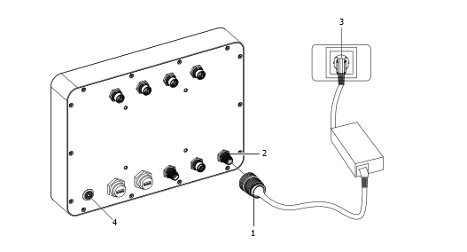
Connect the power supply plug (1) to the power connector (2).
Connect the power supply cable plug (3) into the mains socket.
Switch on the power button (4).
Operation
Ergonomic Guidelines
Consider your workstation as you read through this list of general ergonomic guidelines and see if you can identify areas for improvement in posture, component placement, or work environment.
Take frequent breaks and change work positions frequently.
Adapt the work area to your needs and the work task.
Adjust for convenient reach range by determining where parts or tools should be located to avoid static load.
Use workstation equipment such as tables and chairs appropriate for the work task.
Avoid work positions above shoulder level or with static holding during assembly operations.
When working above shoulder level, reduce the load on the static muscles by reducing the weight of the load. You can also reduce the load on the static muscles by holding the load close to the body.
Make sure to take frequent breaks.
Avoid extreme arm or wrist postures, particularly for operations requiring a degree of force.
Adjust for convenient field of vision by minimizing movement of the eyes and head during the work task.
Use the appropriate lighting for the work task.
Use ear protection equipment in noisy environments.
Use dust extraction system or mouth protection mask in dusty environments.
Operating Instructions
Opening / Closing the Panel PC
Make sure the Panel PC is switched off and the power cord is disconnected.

Remove all the screws on the backside of the Panel PC.
Carefully lift the back unit of the Panel PC to a maximum 25° to access the internal cabling at the front.

Be careful not to damage the connectors.
Carefully disconnect all cables from the back unit of the panel PC before removing any other parts.
The connectors, and especially the display connectors, must be handled with care to prevent damage.
Put the back unit aside with care not to damage the glass surface.
Assemble in reverse order.
Put all screws back in position and tighten them lightly.
Apply the required torque to all screws.
By opening the housing of Assembly Control Mini (Panel PC), all warranty claims are lost.
Additional Information
The rear surface of the panel PC can become very warm. Be careful when touching the rear surface.
Turning the Panel PC On and Off
Use the On/Off breaker to switch On/Off the computer.

Service
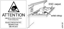
Preventing ESD Problems
The components inside the product and controller are sensitive to electrostatic discharge. To avoid future malfunction, make sure that service and maintenance is carried out in an ESD approved work environment. The figure below shows an example of an appropriate service work station.
Replacing the Bios battery
When BIOS buffer battery is replaced, it should be original part type CR2032. Risk of explosion if battery is replaced by an incorrect type. Dispose of used batteries according to the local or regional regulations or instructions.
Recycling
Environmental Regulations
When a product has served its purpose it has to be recycled properly. Dismantle the product and recycle the components in accordance with local legislation.
Batteries shall be taken care of by your national battery recovery organization.
Recycling Instructions

Pos. | Part | Recycle as |
|---|---|---|
1 | Front module | Steel, Glass |
2 | Gasket | Rubber |
3 | Housing | Steel |
4 | Connector Plate | Aluminum |
5 | Gasket | Rubber |
6 | Cover | Aluminum |
7 | Screw | Metal |
8 | Screw | Metal |
9 | GPIO Connector | Electronics |
10 | USB Connector | Electronics |
11 | On / Switch | Steel, Electronics |
12 | Connector Plate | Steel |
13 | Screw | Metal |