PFD1500RA-1770
Positive feed drill
Product Information
General Information
Safety Signal Words
The safety signal words Danger, Warning, Caution, and Notice have the following meanings:
DANGER | DANGER indicates a hazardous situation which, if not avoided, will result in death or serious injury. |
WARNING | WARNING indicates a hazardous situation which, if not avoided, could result in death or serious injury. |
CAUTION | CAUTION, used with the safety alert symbol, indicates a hazardous situation which, if not avoided, could result in minor or moderate injury. |
NOTICE | NOTICE is used to address practices not related to personal injury. |
Warranty
Product warranty will expire 12 months after the product is first taken into use, but will in any case expire at the latest 13 months after delivery.
Normal wear and tear on parts is not included within the warranty.
Normal wear and tear is that which requires a part change or other adjustment/overhaul during standard tools maintenance typical for that period (expressed in time, operation hours or otherwise).
The product warranty relies on the correct use, maintenance, and repair of the tool and its component parts.
Damage to parts that occurs as a result of inadequate maintenance or performed by parties other than Atlas Copco or their Certified Service Partners during the warranty period is not covered by the warranty.
To avoid damage or destruction of tool parts, service the tool according to the recommended maintenance schedules and follow the correct instructions.
Warranty repairs are only performed in Atlas Copco workshops or by Certified Service Partners.
Atlas Copco offers extended warranty and state of the art preventive maintenance through its ToolCover contracts. For further information contact your local Service representative.
For electrical motors:
Warranty will only apply when the electric motor has not been opened.
Website
Information concerning our Products, Accessories, Spare Parts and Published Matters can be found on the Atlas Copco website.
Please visit: www.atlascopco.com.
ServAid
ServAid is a portal that is continuously updated and contains Technical Information, such as:
Regulatory and Safety Information
Technical Data
Installation, Operation and Service Instructions
Spare Parts Lists
Accessories
Dimensional Drawings
Please visit: https://servaid.atlascopco.com.
For further Technical Information, please contact your local Atlas Copco representative.
Safety Data Sheets MSDS/SDS
The Safety Data Sheets describe the chemical products sold by Atlas Copco.
Please consult the Atlas Copco website for more information www.atlascopco.com/sds.
Country of Origin
For the Country of Origin, please refer to the information on the product label.
Dimensional Drawings
Dimensional Drawings can be found either in the Dimensional Drawings Archive, or on ServAid.
Please visit: http://webbox.atlascopco.com/webbox/dimdrw or https://servaid.atlascopco.com.
Overview
Applications
This high-quality, easy-to-handle pneumatic Positive Feed Drill (PFD) can be used for drilling holes in various metals and composites.
Main components and functions

Pos | Part | Function |
|---|---|---|
1 | Spindle | Main rotating part of the drill. |
2 | Spindle guard | Protects the operator from the rotating spindle. Provides the drill with coolant to the drill bit. |
3 | Head | Transfers rotational torque and feed from the motor to the spindle. |
4 | Feed cassette | Defines spindle feed rate. Measured in inches per revolution (IPR) or millimeters per revolution (mm/rev). |
5 | Air logic | Operates the drill. |
6 | Split gear | Defines rotational speed. Measured in revolutions per minute (RPM). |
7 | Range gear | Defines RPM range. |
8 | Vane motor | Supplies power and rotation to the spindle. |
9 | Motor valve | Supplies the airflow to the vane motor and the emergency stop button. |
10 | Start | Starts the motor and activates drill feed and rotation mechanism. The motor continues to run after the button is released. When spindle reaches the pre-defined drilling depth, it returns automatically to the starting position. |
11 | Rapid advance (optional) | Activates rapid spindle feed. The spindle advances to the work surface faster than the regular feed rate but does not rotate. Releasing the button stops the spindle. |
12 | Retract | Returns the spindle to the starting position at any time during drilling cycle. The motor switches off automatically after retract. |
13 | Emergency stop | Switches off the motor, and stops the spindle at any time during drilling cycle. Once pressed, the emergency stop button locks in position. You must manually reset the emergency stop to restart the drill. |
Technical Product Data
Technical Product Data can be found on either ServAid, or the Atlas Copco website.
Please visit: https://servaid.atlascopco.com or www.atlascopco.com.
Accessories
Overview accessories
For detailed information of accessories, refer to ServAid.
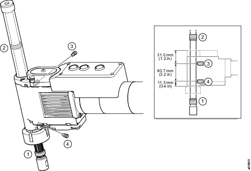
Starting position and drilling depth
Using stop rings, you can define the following parameters:
-
Starting position of the drill bit
-
Drilling depth
|
Pos |
Part |
Function |
|---|---|---|
|
1 |
Starting position ring |
Defines the starting position for drilling. This allows for quick positioning of the drill bit at the pre-defined safe distance to the surface. The starting position can be adjusted. |
|
2 |
Depth ring |
Defines the drilling depth. |
|
3 |
Depth valve |
Controls the drilling depth. Once the depth ring reaches the valve, it activates the valve, and the spindle retracts into the starting position. The motor automatically switches off after retract. |
|
4 |
Starting position valve |
Controls the starting position for drilling. Once the starting position ring reaches the valve, it activates the valve that switches off the motor. |
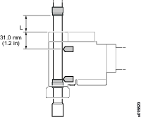
You can calculate the distance between the depth ring and the drill head (dimension L in the figure below) for the desired drill depth D according to the following formula:
L (mm) =D (mm) – 31.0 mm
L (in) = D (in) – 1.2 in
Speed
The combination of range and split gears determines the speed of the drill spindle. Make a selection from the available combinations of range and split gears in the table below to get the desired RPM.
Range gear | ||
|---|---|---|
RPM | Ordering No. | Split gear ratio |
38 | 4141 0043 95 | Low |
50 | 4141 0043 95 | 1:1 |
67 | 4141 0043 95 | High |
100 | 4141 0043 92 | Low |
140 | 4141 0043 92 | 1:1 |
180 | 4141 0043 92 | High |
200 | 4141 0043 90 | Low |
270 | 4141 0043 90 | 1:1 |
360 | 4141 0043 90 | High |
400 | 4141 0043 94 | Low |
530 | 4141 0043 94 | 1:1 |
700 | 4141 0043 94 | High |
670 | 4141 0043 93 | Low |
900 | 4141 0043 93 | 1:1 |
1200 | 4141 0043 93 | High |
1330 | 4141 0043 91 | Low |
1770 | 4141 0043 91 | 1:1 |
2360 | 4141 0043 91 | High |
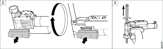
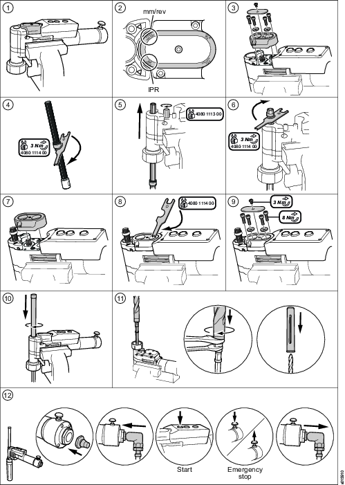
A split gear ratio can be set to high, 1:1 or low depending on the position of the shaft (1) in the relation to the indent (2), see the figure below. Markings on the split gear housing indicate ratios corresponding to shaft positions.
Secure that the shaft is in the right position with the fork-shaped tool (4141 1114 00). See the figure below.


Velocity rapid advance – PFD1500RA-R (only for models with rapid advance)
The rapid advance is depending on the feed rate. High feed rate generates high rapid advance and vice versa.
Model |
Spindle (rpm) | Velocity rapid advance (mm/s), ±10% | Velocity rapid advance (inch/s), ±10% |
|---|---|---|---|
PFD 1500RA-38-R | 38 | 1.4 | 0.06 |
PFD 1500RA-50-R | 50 | 1.9 | 0.07 |
PFD 1500RA-67-R | 67 | 2.5 | 0.10 |
PFD1500RA-100-R | 100 | 3.7 | 0.15 |
PFD1500RA-140-R | 140 | 5.2 | 0.20 |
PFD1500RA-180-R | 180 | 6.7 | 0.26 |
PFD1500RA-200-R | 200 | 7.4 | 0.29 |
PFD1500RA-270-R | 270 | 10.0 | 0.39 |
PFD1500RA-360-R | 360 | 13.3 | 0.52 |
PFD1500RA-400-R | 400 | 14.8 | 0.58 |
PFD1500RA-530-R | 530 | 19.7 | 0.78 |
PFD1500RA-670-R | 670 | 24.8 | 0.98 |
PFD1500RA-700-R | 700 | 25.9 | 1.02 |
PFD1500RA-900-R | 900 | 33.3 | 1.31 |
PFD1500RA-1200-R | 1200 | 44.5 | 1.75 |
PFD1500RA-1330-R | 1330 | 49.2 | 1.94 |
PFD1500RA-1770-R | 1770 | 65.6 | 2.58 |
PFD1500RA-2360-R | 2360 | 87.4 | 3.44 |
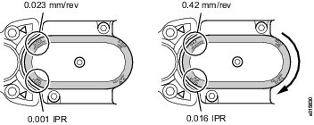
Feed rate
The feed rate of the drill must be balanced with the spindle speed. Make a selection from the available combinations of feed rate in the table below to get the desired feed rate. Normally a feed cassette can define two feed rates. By turning it 180 degrees you can change the feed rates, as shown in the figure below.
Feed cassette | ||
|---|---|---|
IPR | mm/rev | Ordering No. |
0.001 | 0.023 | 4141 0034 91 |
0.002 | 0.05 | 4141 0034 92 |
0.003 | 0.075 | 4141 0034 93 |
0.004 | 0.10 | 4141 0034 94 |
0.006 | 0.16 | 4141 0034 95 |
0.008 | 0.21 | 4141 0034 96 |
0.010 | 0.27 | 4141 0034 95 |
0.013 | 0.33 | 4141 0034 94 |
0.014 | 0.36 | 4141 0034 93 |
0.015 | 0.38 | 4141 0034 92 |
0.016 | 0.42 | 4141 0034 91 |
Service Overview
Service Recommendations
Preventive maintenance is recommended at regular intervals. See the detailed information on preventive maintenance. If the product is not working properly, take it out of service and inspect it.
If no detailed information about preventive maintenance is included, follow these general guidelines:
Clean appropriate parts accurately
Replace any defective or worn parts
Installation
Installation Requirements
Air quality
Poor air quality may cause damage to the tool and reduce the performance.
-
For optimum performance and maximum product life we recommend the use of compressed air with a maximum dew point of -5°C (23°F). We also recommend to install an Atlas Copco refrigeration type air dryer.
-
Use a separate air filter which removes solid particles larger than 30 microns and more than 90% of liquid water. Install the filter as close as possible to the tool and prior to any other air preparation units to avoid pressure drop.
-
Lubrication free tools are a better choice from an environmental perspective.
-
Lubrication will shorten the life time of the turbine motor and once lubricated, you will need to continue with the lubrication.
Air Lubrication Guide
Brand | Air lubrication |
|---|---|
Atlas Copco | Optimizer (1 liter) 9090 0000 04 |
Q8 | Chopin 46 |
Shell | Shell Air Tool Oil S2 A 320 |
Compressed Air Connection
For correct air pressure and hose size, see the Technical Product Data on - https://servaid.atlascopco.com or www.atlascopco.com.
Make sure that the hose and couplings are clean and free from dust before connecting to the tool.
Installation Instructions
Installing the rapid advance kit
Required tools
-
Vise
-
Spanners
-
Allen key
-
Fork-shaped tool
-
Hexagonal tool
-
Torx wrench
-
Fasten the drill in a vise with rubber pads, with the front part upwards and the drill handle to the right. Remove the front part and the drill bit using spanners.
-
Loosen the drill. Turn the drill over and fasten the drill in the vise.
-
Remove the spindle guard.
-
Remove the depth ring from the spindle using a fork-shaped tool.
-
Note the position of the feed cassette. The markings, on the cassette end closest to the spindle, indicate the actual feed rate.
-
Remove the feed cassette using an allen key.
-
Feed the spindle out of the socket by turning a hexagonal tool counterclockwise until the spindle is removed.
-
Remove the air logic cover and the air logic unit using an allen key.

Do not loose the o-rings on top of the head.
-
Loosen the cylinder using an allen key.
-
Loosen the drill. Turn the drill over and fasten the drill in the vise.
-
Remove the lower part of the head using an allen key.
-
Remove the cylinder from the lower head.
-
Replace the cylinder with the new one (included in the kit) and put it back in position. Fasten the cylinder using an allen key.
-
Pull out the bevel gear straight up from the head.
-
Pull out the cylinder straight down from the head.
-
Replace the cylinder with the new one (included in the kit). Put it back in position.
-
Replace the bevel gear with the new one (included in the kit and put it back in position.
-
Put the lower head back in original position. Tighten it with screws.
-
Loosen the drill. Turn the drill over and fasten the drill in the vise.
-
Fasten the cylinder with screws using an allen key.
-
Put the air logic unit back in original position. Replace the cover with the new one (included in the kit) and put it back in position.
-
Install the spindle in the socket from below. Turn a hexagonal tool clockwise several turns to feed the spindle.
-
Install the depth ring onto the spindle and move it in position. Tighten the ring with the fork-shaped tool.
-
Put the feed cassette in the original position making sure that the markings on the cassette end closest to the spindle indicate the required feed rate.
-
If you cannot install the cassette easily, turn its splines with the fork-shaped tool to align them.
-
Install the washers and the four screws in the original position. Tighten the screws. Install the lock and the lock screw. Tighten the screw.
-
Put the spindle guard back in the original position and secure it.
-
Lossen the drill. Turn the drill over and fasten the drill in the vise. Put the drill bit in the spindle. Place spanners on the spindle socket and the drill bit base to keep them from rotating and tighten the connection. Put the front part over the drill and secure it.
-
Loosen the drill. Turn the drill over and fasten it in the vise. Connect the air hose to the nipple. Do a functional test of the emergency stop button:
-
Push the start button.
-
Push the emergency stop button so that it locks in position. The spindle must stop immediately.
-
Pull the emergency stop button to reset it. The motor must not restart.
-
Disconnect the air hose.
-


Changing the spindle
Required tools
-
Vise
-
Fork-shaped tool
-
Hexagonal tool
-
Torx wrench
-
Allen key
-
Spanners
-
Fasten the drill in a vise with rubber pads, with the front part upward and the drill handle to the right. Remove the front part and the drill bit.
-
Turn the drill over and fasten it in the vise. Remove the spindle guard.
-
Remove the depth ring from the spindle with the fork-shaped tool.
-
Note the position of the feed cassette. The markings, on the cassette end closest to the spindle, indicate the actual feed rate.
-
Remove the feed cassette.
-
Feed the spindle out of the socket by turning a hexagonal tool counterclockwise. Remove the spindle.
-
Perform the steps 4 to 11 in the section “installing the drill”.
-
Turn the drill over and fasten it in the vise. Connect the air hose to the nipple. Do a functional test of the emergency stop button:
-
Push the start button.
-
Push the emergency stop button so that it locks in position. The spindle must stop immediately.
-
Pull the emergency stop button to reset it. The motor must not restart.
-
Disconnect the air hose.
-


Installing the scraper kit, for drills with indexer
Required tools
Vise
Spanner
Allen key
Mounting tool
Prerequisites
Before installing the scraper kit, make sure that the following components are removed:
Front part
Drill bit
Spindle
Spindle guard
Fasten the drill in a vise.
Remove the adapter and the screw.
Put the indexer housing in position on the adapter shaft.
Apply a few drops of thread locker on the nut threads and fasten the nut on the indexer housing. Tighten the nut.
Put the wave washer in position on the indexer housing. Apply a few drops of thread locker on the shaft and attach it to the indexer housing.
Push the button on the index housing so the nut easily moves down to the bottom. Tighten the front nut on the shaft onto the index housing with a hook wrench.
Remove the stop nuts on the spindle.
Install a scraper ring on the spindle and fasten it with four screws.
Make sure that the chamfered edge of the scraper ring is pointing towards the drill bit.
Install the spindle stop nut on the spindle.
Install the spindle in the drill.
Install the spindle stop nut on the spindle top.
Cut the tube to fit the length of the front part.
The scraper ring on the spindle shall not move outside the tube when drilling.
Install the tube and tighten it.
Make sure that the scraper ring runs smoothly to prevent thread damage.
Install the front part.


Installing the drill
Required tools
-
Vise
-
Torx wrench
-
Allen key
-
Fork-shaped tool
-
Hexagonal tool
-
Spanners
-
Fasten the drill in a vise with rubber pads, with the air logic unit upward and the drill handle to the right.
-
Note the position of the feed cassette. The markings, on the cassette end closest to the spindle, indicate the actual feed rate.
-
Remove the cassette lock, the cassette, the five screws and two washers. Use a Torx wrench on the screw of the cassette lock and allen key on the other four screws.
-
If applicable, install the starting position ring onto the spindle, and move it in position. Tighten the ring with a fork-shaped tool.
-
Install the spindle in the socket from below. Turn a hexagonal tool clockwise several turns to feed the spindle.
-
Install the depth ring onto the spindle and move it in position. Tighten the ring with the fork-shaped tool.
-
Put the feed cassette in the original position making sure that the markings on the cassette end closest to the spindle indicate the required feed rate.
-
If you cannot install the cassette easily, turn its splines with the fork-shaped tool to align them.
-
Install the washers and the four screws in the original position. Tighten the screws. Install the lock and the lock screw. Tighten the screw.
-
Put the spindle guard back in the original position and secure it.
-
Turn the drill upside-down and fasten it in the vise. Put the drill bit in the spindle. Place spanners on the spindle socket and the drill bit base to keep them from rotating and tighten the connection. Put the front part over the drill and secure it.
-
Turn the drill over and fasten it in the vise. Attach a nipple for an air hose to the connector on the drill. Connect the air hose to the nipple. Do a functional test of the emergency stop button:
-
Push the start button.
-
Push the emergency stop button so that it locks in position. The spindle must stop immediately.
-
Pull the emergency stop button to reset it. The motor must not restart.
-
Disconnect the air hose.
-
Installing the indexer
Reqired tools
Vise
Spanner
Allen key
Pin spanner
Hook wrench
Prerequisites
Before installing the indexer, make sure that the following components are removed:
Front part
Drill bit
Spindle
Spindle guard
Fasten the drill in a vise with rubber pads, with the air logic unit downwards and the drill handle to the right.
Remove the adapter that fastens the front part using a spanner. Remove the screw on the right side of the adapter hole using an allen key.
Put the large hole on the index housing in position over the adapter hole, with the push button against you. If the index housing is put in correct position, the plug to the right of the screw hole will now fit into the index housing.
Put the nut into the index housing, with the threads downwards. Tighten the nut with a pin spanner.
Put the waved washer and the shaft, with the splines downwards, into the index housing.
Push the button on the index housing so the nut easily moves down to the bottom. Tighten the front nut on the shaft onto the index housing with a hook wrench.
Install the components in the list above after finishing the installation.
Installing the ChipLet
Required tools
-
Vise
-
Torx screwdriver
-
Allen key
-
Mounting tool
Prerequisites
Before installing the ChipLet, make sure that the following components are removed:
-
Front part
-
Drill bit
-
Spindle
-
Spindle guard
-
Fasten the drill in a vise.
-
Remove the screw and the feed cassette cover.
-
Remove the four screws with the two washers and the feed cassette.
-
Remove the depth position valve.
-
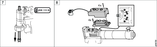
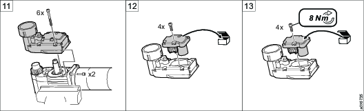
Remove the two screws and the cap.
-
Remove the thrust washer.
-
Put the chiplet with the o-ring in position. A click sound is heard when the chiplet is in position.
-
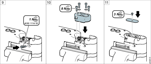
Fasten the chiplet with two screws and tighten them to 8 Nm.
-
Put the depth position valve back in position, fasten it and tighten to 1 Nm.
-
Put the feed cassette back in position and fasten the four screws and two washers to 8 Nm.
-
Put the cassette cover back in position on the cassette and fasten it with one screw to 3 Nm.


Changing the air inlet adapter
All PFD1500 tools will be delivered with NPT air inlet adapter as standard. Additional BSP air inlet adapter will be included in the box together with the tool on delivery.
Required tools
Vise
Spanner
Remove the adapter.
Make sure that the filter is still in place.
Replace the adapter with the new one (included in the box). Move the o-ring from the old adapter to the new one.
Put the adapter back in original position. Tighten the adapter.
Make sure that the filter is in position.

Installing the scraper kit, for drills without indexer
Required tools
-
Vise
-
Spanner
-
Allen key
-
Mounting tool
-
Saw
Prerequisites
Before installing the scraper kit, make sure that the following components are removed:
-
Front part
-
Drill bit
-
Spindle
-
Spindle guard
-
Fasten the drill in a vise.
-
Remove the adapter.
-
Remove the stop nuts on the spindle.
-
Install a scraper ring on the spindle and fasten it with four screws.
Make sure that the chamfered edge of the scraper ring is pointing towards the drill bit.
-
Install the spindle stop nut on the spindle.
-
Install the spindle in the drill.
-
Install the spindle stop nut on the spindle top.
-
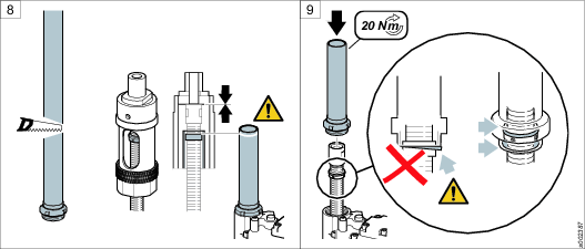
Cut the tube to fit the length of the front part.
The scraper ring on the spindle shall not move outside the tube when drilling.
-
Install the tube and fasten it to 20 Nm.
Make sure that the scraper ring runs smoothly to prevent thread damage.
Install the front part.


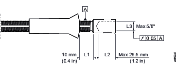
Preparation for the spindles 4141 0253 XX
Using this spindle, you can define your own thread size.
Before you make preparations for the spindle, read the following instructions:
-
Remove the rings from the spindle.
-
Insert the spindle in a collet chuck with Ø16 mm.
-
Clamp the collet chuck over the spindle thread. The thread should not stick out more than (L1). See figure below.
-
Note the dimension of the drilling depth (L2) and the thread size (L3). See figure below.
Operation
Ergonomic guidelines
Consider your workstation as you read through this list of general ergonomic guidelines and see if you can identify areas for improvement in posture, component placement, or work environment.
Take frequent breaks and change work positions frequently.
Adapt the work area to your needs and the work task.
Adjust for convenient reach range by determining where parts or tools should be located to avoid static load.
Use workstation equipment such as tables and chairs appropriate for the work task.
Avoid work positions above shoulder level or with static holding during assembly operations.
When working above shoulder level, reduce the load on the static muscles by reducing the weight of the load. You can also reduce the load on the static muscles by holding the load close to the body.
Make sure to take frequent breaks.
Avoid extreme arm or wrist postures, particularly for operations requiring a degree of force.
Adjust for convenient field of vision by minimizing movement of the eyes and head during the work task.
Use the appropriate lighting for the work task.
Use ear protection equipment in noisy environments.
Use dust extraction system or mouth protection mask in dusty environments.
Configuration Instructions
Replacing modules
You can easily replace all drill modules:

Pos | Module |
|---|---|
1 | Head |
2 | Feed cassette |
3 | Air logic |
4 | Split gear |
5 | Range gear |
6 | Vane motor |
7 | Motor valve |
Changing the speed
-
Remove the motor valve, the vane motor and the range gear.
-
If applicable, change the split gear ratio as follows:
-
Remove the split gear.
-
Shift the shaft (1) of the split gear to set the required ratio. See the figure below. A click indicates that the shaft has shifted as desired. Secure that the shaft is in the right position with the fork-shaped tool (4141 1114 00), see the section “speed”.
-
Line up the split gear holes over the bolts, making sure that the shaft head faces the drill head.
-
Carefully slide the split gear into position. Turn the spline shaft (2) until the shaft (1) fits in place.
-
Holding the pinion (3) in place with the fork-shaped tool (4080 1114 00), turn the spline shaft (2) and gently push the split gear forward until the shaft (1) fits on the pinion.
-
Gently push the split gear forward until it clicks in place.
-
-
If applicable, install a new range gear. Otherwise, restore the old one to its original position. Turn the planetary gear to align the splines.
-
Restore the vane motor and the motor valve to their original position. Turn the rotor counterclockwise with the fork-shaped tool (4080 1114 00) to align the splines.
-
Before operating the drill, do a functional test of the emergency stop button:
-
Push the start button.
-
Push the emergency stop so that it locks in position. The spindle must stop immediately.
-
Pull the emergency stop button to reset it. The motor must not restart.
-
Disconnect the air hose.
-
Reconnect the air hose.
-

Changing the feed rate
By turning the feed cassette 180 degrees you can change the cassette feed rates. If you desire a different feed rate, select the appropriate cassette from the table feed rates in the section “Overview”.
Remove the old cassette.
Put the new cassette in position. Before you secure the cassette, read the marking on the cassette end closest to the spindle to make sure that the orientation of the cassette is correct.
Before operating the drill, do a functional test of the emergency stop button:
Push the start button.
Push the emergency stop button so that it locks in position. The air supply to the motor switches off and the spindle stops.
Disconnect the air hose.
Pull the emergency stop button to reset it.
Reconnect the air hose.
Operating Instructions
Before drilling operation

Following conditions apply prior to operating the drill:
Front part locked in the fixture.
Air hose connects to the drill.
Push the start button.
Push the emergency stop button so that it locks in position. The spindle must stop immediately.
Pull the emergency stop button to reset it. The motor must not restart.
Disconnect the air hose.
Reconnect the air hose.
Lock the tool in the jig.
Release the indexer to adjust the position of the tool by pushing in the button on the indexer.
Release the button on the indexer to lock in position.
Check that the lock pin on the indexer is level to the nut surface.
Rock the tool from side to side to confirm the tool being locked in position.


Operating the drill
You can operate the drill as follows:
To quickly advance the drill bit to the work surface... | push the rapid advance button (optional). Make sure to stop the drill bit at a safe distance from the work surface. |
To start drilling... | push the start button. |
To stop drilling and retract the spindle into the start position... | push the retract button. |
To switch off the motor in case of emergency... | push the emergency stop button. |
To reset the emergency stop and restore normal operation... | pull the emergency stop button. Disconnect the air hose, and then reconnect it to reset the air logic. |
Service
Maintenance Instructions
Service Recommendations
Preventive maintenance is recommended at regular intervals. See the detailed information on preventive maintenance. If the product is not working properly, take it out of service and inspect it.
If no detailed information about preventive maintenance is included, follow these general guidelines:
Clean appropriate parts accurately
Replace any defective or worn parts
Preventive Maintenance
Preventive maintenance
Daily maintenance: test of the emergency stop button.
Maintenance recommendations in the tables below are for drilling holes in aluminum and titanium.
For content of each kit, please see spare parts list.
Spindle
Drill bit/Material | Drill bit/Material | Drill bit/Material | |
|---|---|---|---|
<1/2" Titan/Alu | <3/4" Titan/Alu | <1 1/4" Titan/Alu | |
Cycles | (Use kit, Ordering No.)* | (Use kit, Ordering No.)* | (Use kit, Ordering No.)* |
Every 1000 drilled holes | |||
Every 3000 drilled holes | 4141 0087 80, 4141 0087 90 | ||
Every 6000 drilled holes | 4141 0087 80, 4141 0087 90 | 4141 0087 80, 4141 0087 90 | |
Every 12000 drilled holes | |||
Every 24000 drilled holes | |||
Every 48000 drilled holes |
* Please order the correct kit for your specific spindle, see spare part list.
Feed cassette
Drill bit/Material | Drill bit/Material | Drill bit/Material | |
|---|---|---|---|
<1/2" Titan/Alu | <3/4" Titan/Alu | <1 1/4" Titan/Alu | |
Cycles | (Use kit, Ordering No.)* | (Use kit, Ordering No.)* | (Use kit, Ordering No.)* |
Every 1000 drilled holes | |||
Every 3000 drilled holes | |||
Every 6000 drilled holes | |||
Every 12000 drilled holes | 4141 0034 91, 4141 0034 92 4141 0034 93, 4141 0034 94 4141 0034 95, 4141 0034 96 | ||
Every 24000 drilled holes | 4141 0034 91, 4141 0034 92 4141 0034 93, 4141 0034 94 4141 0034 95, 4141 0034 96 | ||
Every 48000 drilled holes | 4141 0034 91, 4141 0034 92 4141 0034 93, 4141 0034 94 4141 0034 95, 4141 0034 96 |
* Please order the correct kit for your specific feed cassette, see spare part list.
Vane motor (dry air)
Drill bit/Material | Drill bit/Material | Drill bit/Material | |
|---|---|---|---|
<1/2" Titan/Alu | <3/4" Titan/Alu | <1 1/4" Titan/Alu | |
Cycles | (Use kit, Ordering No.) | (Use kit, Ordering No.) | (Use kit, Ordering No.) |
Every 1000 drilled holes | |||
Every 3000 drilled holes | 4081 0457 90 | 4081 0457 90 | |
Every 6000 drilled holes | 4081 0457 90 | ||
Every 12000 drilled holes | |||
Every 24000 drilled holes | |||
Every 48000 drilled holes | 4141 0168 90 | 4141 0168 90 | 4141 0168 90 |
Range gear
Drill bit/Material | Drill bit/Material | Drill bit/Material | |
|---|---|---|---|
<1/2" Titan/Alu | <3/4" Titan/Alu | <1 1/4" Titan/Alu | |
Cycles | (Use kit, Ordering No.)* | (Use kit, Ordering No.)* | (Use kit, Ordering No.)* |
Every 1000 drilled holes | 4141 0037 90, 4141 0037 91 4141 0037 92, 4141 0037 94 4141 0037 95 | ||
Every 3000 drilled holes |
| ||
Every 6000 drilled holes | 4141 0037 90, 4141 0037 91 4141 0037 92, 4141 0037 94 4141 0037 95 | ||
Every 12000 drilled holes | 4141 0037 90, 4141 0037 91 4141 0037 92, 4141 0037 93 4141 0037 94, 4141 0037 95 | ||
Every 24000 drilled holes | |||
Every 48000 drilled holes |
* Please order the correct kit for your specific range gear, see spare part list.
Head
Drill bit/Material | Drill bit/Material | Drill bit/Material | |
|---|---|---|---|
<1/2" Titan/Alu | <3/4" Titan/Alu | <1 1/4" Titan/Alu | |
Cycles | (Use kit, Ordering No.) | (Use kit, Ordering No.) | (Use kit, Ordering No.) |
Every 1000 drilled holes | |||
Every 3000 drilled holes | 4141 0063 90 | ||
Every 6000 drilled holes | 4141 0063 90 | 4141 0063 90 | 4141 0012 91b, 4141 0012 92a, 4141 0019 91 |
Every 12000 drilled holes | 4081 0452 90, 4081 0453 90, 4081 0454 90a, 4081 0455 90b | ||
Every 24000 drilled holes | 4141 0012 91b, 4141 0012 92a 4141 0007 90b, 4141 0007 91a 4141 0019 91 | 4081 0452 90, 4081 0453 90, 4081 0454 90a, 4081 0455 90b, 4141 0007 90b, 4141 0007 91a 4141 0012 91b, 4141 0012 92a, 4141 0019 91 | 4141 0007 90b, 4141 0007 91a 4141 0012 91b, 4141 0012 92a, 4141 0019 91 |
Every 48000 drilled holes | 4081 0452 90, 4081 0453 90, 4081 0454 90a, 4081 0455 90b |
a – Only for models with rapid advance. b – Only for models without rapid advance.
Motor valve
Drill bit/Material | Drill bit/Material | Drill bit/Material | |
|---|---|---|---|
<1/2" Titan/Alu | <3/4" Titan/Alu | <1 1/4" Titan/Alu | |
Cycles | (Use kit, Ordering No.) | (Use kit, Ordering No.) | (Use kit, Ordering No.) |
Every day | Test function* | Test function* | Test function* |
Every 1000 drilled holes | |||
Every 3000 drilled holes | |||
Every 6000 drilled holes | |||
Every 12000 drilled holes | |||
Every 24000 drilled holes | 4141 0102 91 | 4141 0102 91 | 4141 0102 91 |
Every 48000 drilled holes |
* Emergency stop.
Split gear
Drill bit/Material | Drill bit/Material | Drill bit/Material | |
|---|---|---|---|
<1/2" Titan/Alu | <3/4" Titan/Alu | <1 1/4" Titan/Alu | |
Cycles | (Use kit, Ordering No.) | (Use kit, Ordering No.) | (Use kit, Ordering No.) |
Every 1000 drilled holes | 4141 0051 90 | ||
Every 3000 drilled holes | |||
Every 6000 drilled holes | 4141 0051 90 | ||
Every 12000 drilled holes | |||
Every 24000 drilled holes | 4141 0051 90 | ||
Every 48000 drilled holes |
Vane motor (lubricated air)
Drill bit/Material | Drill bit/Material | Drill bit/Material | |
|---|---|---|---|
<1/2" Titan/Alu | <3/4" Titan/Alu | <1 1/4" Titan/Alu | |
Cycles | (Use kit, Ordering No.) | (Use kit, Ordering No.) | (Use kit, Ordering No.) |
Every 1000 drilled holes | |||
Every 3000 drilled holes | |||
Every 6000 drilled holes | |||
Every 12000 drilled holes | |||
Every 24000 drilled holes | 4081 0457 90 | 4081 0457 90 | |
Every 48000 drilled holes | 4141 0168 90, 4081 0457 90 | 4141 0168 90 | 4141 0168 90 |
Air logic
Drill bit/Material | Drill bit/Material | Drill bit/Material | |
|---|---|---|---|
<1/2" Titan/Alu | <3/4" Titan/Alu | <1 1/4" Titan/Alu | |
Cycles | (Use kit, Ordering No.) | (Use kit, Ordering No.) | (Use kit, Ordering No.) |
Every 1000 drilled holes | |||
Every 3000 drilled holes | |||
Every 6000 drilled holes | 4141 0164 90 | ||
Every 12000 drilled holes | 4141 0164 90 | 4141 0164 90 | |
Every 24000 drilled holes | |||
Every 48000 drilled holes |
Lubrication Instructions
Rust protection and cleaning
Water in the compressed air can cause rust. To prevent rust we strongly recommend to install an air dryer.
Water and particles can cause sticking of vanes and valves. This can be prevented by installing an air filter close to the product to avoid pressure drop.
Lubrication guide
Valid lubricants:
Lubricant | Description |
|---|---|
A | Klübersynth PEG 46-121. Can filled with 1 KG grease, (Ordering No. 4081 0487 90). |
B | Vane motor oil (Q8 Chopin S46) |
All O-rings shall be greased before assembly with lubricant A or B (thin layer).
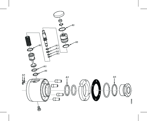
Split gear
Total amount of lubrication: 15 ml.

Pos | Description |
|---|---|
A1 | Ensure that the radial seals are filled with lubricant A before assembly, also lubricate the outside and sliding surfaces. |
A2 | Ensure that needle bearings are completely filled with lubricant A. |
Indexer 4141 0912 90
Pos | Description |
|---|---|
A1 | Apply a thin layer of lubricant A. |
A2 | Ensure that the O-rings are well greased with lubricant A. |
A3 | Ensure that all cog gaps are well filled with lubricant A. |
Range gear
Total amount of lubrication: 27 ml.
Turn gear while lubricating at least two turns.
Ensure that gear is running normally without hacking.

Pos | Description |
|---|---|
A1 | Ensure that the outside and sliding surface of the radial seals are lubricate with lubricant A before assembly. |
A2 | Ensure that needle bearings are completely filled with lubricant A. |
A3 | Ensure that the O-rings are well greased with lubricant A. |
Range gear
Total amount of lubrication: 15 ml.
Turn gear while lubricating at least two turns.
Ensure that gear is running normally without hacking.

Pos | Description |
|---|---|
A1 | Ensure that the outside and sliding surface of the radial seals are lubricate with lubricant A before assembly. |
A2 | Ensure that needle bearings are completely filled with lubricant A. |
A3 | Ensure that the O-rings are well greased with lubricant A. |
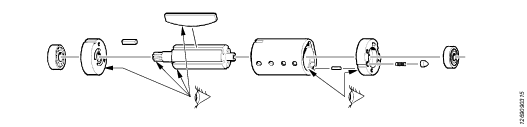
Motor
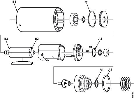
Pos | Description |
|---|---|
A1 | Ensure that the O-rings are well greased with lubricant A. |
B2 | Apply a thin layer of lubricant B on end plates (shall cover rotor diameter). |
B3 | Inside cylinder (complete motor, add two drops of lubricant B through entrance hole at back end plate, turn rotor so the oil will spread in motor). |
Indexer 4141 0306 91

Pos | Description |
|---|---|
A1 | Apply a thin layer of lubricant A. |
A2 | Ensure that the O-rings are well greased with lubricant A. |
A3 | Ensure that all cog gaps are well filled with lubricant A. |
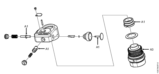
Motor valve
Pos | Description |
|---|---|
A1 | Apply a thin layer of lubricant A. |
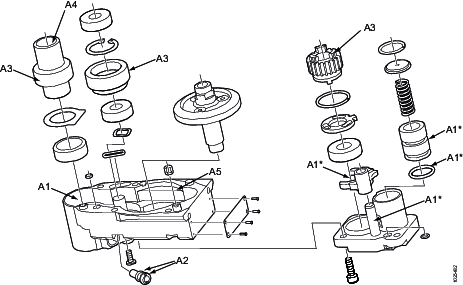
Head

Total amount of lubrication: 28 ml.
Pos | Description |
|---|---|
A1 | Apply a thin layer of lubricant A. |
A2 | Ensure that the O-rings are greased with lubricant A. |
A3 | Ensure that all cog gaps are well filled with lubricant A. |
A4 | Fill inner trapezoidal thread with lubricant A. |
A5 | Ensure that all cog gaps are well filled with lubricant A (5 ml per part). |
Pos | Description |
|---|---|
A1 | Apply a thin layer of lubricant A. |
A2 | Ensure that the O-rings are well greased with lubricant A. |
A3 | Ensure that all cog gaps are well filled with lubricant A. |
A4 | Apply a thin layer of lubricant A inside. |
A5 | Apply minimum 10 ml of lubricant A. |
* Only for models with rapid advance.

Pos | Description |
|---|---|
A1 | Ensure that all cog gaps are well filled with lubricant A (5 ml per part). |
A2 | Ensure that the O-rings are well greased with lubricant A. |
Repair Instructions
Release the spindle
Required tools
-
Vise
-
Torx wrench
-
Allen key
-
Pin spanner
-
Wrench
-
Fork-shaped tool
-
Fasten the drill in a vise with rubber pads, with the air logic unit upward and the drill handle to the right. Remove the spindle guard.
-
Note the position of the feed cassette. The markings, on the cassette end closest to the spindle, indicate the actual feed rate.
-
Remove the cassette lock, the cassette, the five screws and two washers. Use a Torx wrench on the screw of the cassette lock and allen key on the other four screws.
-
Pull out the clutch.
-
Put the pin spanner in the original position of the clutch, with the four pin facing down. Turn the spanner until the pin locks into position.
-
Note the position of the spindle:
-
If the spindle is in starting position – Turn the pin spanner counterclockwise with a wrench until the spindle is released.
-
If the spindle is in finishing drilling position – Turn the pin spanner clockwise with a wrench until the spindle is released.
-
-
Pull out the pin spanner.
-
Install the clutch in the original position.
-
Put the feed cassette in the original position making sure that the markings on the cassette end closest to the spindle indicate the required feed rate.
-
If you cannot install the cassette easily, turn its splines with the fork-shaped tool to align them.
-
Install the washers and the four screws in the original position. Tighten the screws. Install the lock and the lock screw. Tighten the screw.
-
Put the spindle guard back in the original position and secure it.
-
Connect the air hose to the nipple. Do a functional test of the emergency stop button:
-
Push the start button.
-
Push the emergency stop button so that it locks in position. The spindle must stop immediately.
-
Pull the emergency stop button to reset it. The motor must not restart.
-
Disconnect the air hose.
-
Before using the tool, test the starting position valve and the depth valve to ensure previous malfunction.
Step 1 – Make a visible test. Remove the valves from the tool. Turn the valves clockwise with the fork-shaped tool. Compress the valves and see if the spring is OK.
Step 2 – See section “Leak test”.

Dismantling/Assembling Instructions
Instructions for vane motor
Dismantling
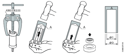
Service tools are also included in the Basic Service Tools set. For further information see ordering No. 9835 5485 00
Dismantling tool Mandrel A
Ordering No. | Ø D | Ø C |
|---|---|---|
4080 0182 01 | 7 | 3.5 |
4080 0182 02 | 8 | 4.5 |
4080 0182 03 | 9 | 5.5 |
4080 0182 04 | 10 | 6.5 |
4080 0182 05 | 13 | 8.5 |
4080 0182 06 | 16 | 10.5 |
4080 0182 07 | 19 | 12.5 |
4080 0182 08 | 22 | 15.5 |
4080 0182 09 | 24 | 17.5 |
4080 0182 10 | 26 | 20.5 |
4080 0182 11 | 30 | 25.5 |
4080 0182 12 | 35 | 30.5 |
4080 0182 13 | 40 | 35.5 |
4080 0182 14 | 47 | 40.5 |
Inspection of motor parts
Assembling - According to Bäckströms method
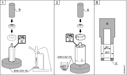
Service tools are also included in the Basic Service Tools set. For further information see ordering No. 9835 5485 00
Dismantling tool Mandrel B
Ordering No. | Ø D | Ø C |
|---|---|---|
4080 0567 04 | 12.5 | 5.2 |
4080 0567 11 | 14.5 | 6.5 |
4080 0567 01 | 15.5 | 5.2 |
4080 0567 05 | 18.5 | 6.2 |
4080 0567 02 | 18.5 | 8.2 |
4080 0567 06 | 21.5 | 7.5 |
4080 0567 03 | 21.5 | 8.2 |
4080 0567 07 | 25.5 | 10.5 |
4080 0567 08 | 27.5 | 12.5 |
4080 0567 09 | 31.5 | 15.5 |
4080 0567 10 | 34.5 | 18.5 |
Instructions for vane motor
Dismantling
Service tools are also included in the Basic Service Tools set. For further information see ordering No. 9835 5485 00
Dismantling tool Mandrel A
Ordering No. | Ø D | Ø C |
|---|---|---|
4080 0182 01 | 7 | 3.5 |
4080 0182 02 | 8 | 4.5 |
4080 0182 03 | 9 | 5.5 |
4080 0182 04 | 10 | 6.5 |
4080 0182 05 | 13 | 8.5 |
4080 0182 06 | 16 | 10.5 |
4080 0182 07 | 19 | 12.5 |
4080 0182 08 | 22 | 15.5 |
4080 0182 09 | 24 | 17.5 |
4080 0182 10 | 26 | 20.5 |
4080 0182 11 | 30 | 25.5 |
4080 0182 12 | 35 | 30.5 |
4080 0182 13 | 40 | 35.5 |
4080 0182 14 | 47 | 40.5 |
Inspection of motor parts
Assembling - According to Bäckströms method
Service tools are also included in the Basic Service Tools set. For further information see ordering No. 9835 5485 00
Dismantling tool Mandrel B
Ordering No. | Ø D | Ø C |
|---|---|---|
4080 0567 04 | 12.5 | 5.2 |
4080 0567 11 | 14.5 | 6.5 |
4080 0567 01 | 15.5 | 5.2 |
4080 0567 05 | 18.5 | 6.2 |
4080 0567 02 | 18.5 | 8.2 |
4080 0567 06 | 21.5 | 7.5 |
4080 0567 03 | 21.5 | 8.2 |
4080 0567 07 | 25.5 | 10.5 |
4080 0567 08 | 27.5 | 12.5 |
4080 0567 09 | 31.5 | 15.5 |
4080 0567 10 | 34.5 | 18.5 |
Assembling Indexer
Perform the following steps to assemble the indexer or moving it to another tool:
Loosen the nut that connects the indexer to the tool's head.
Clean the thread of the nut from glue.
Check the splines on the lower part that is attached to the front part of the indexer for damage. Clean off any glue.
Check the splines on the lock pin on the indexer's upper housing for damage and clean off any glue. As the indexer is parted, push the button to ensure that the lock pin on the indexer runs smoothly in and out of the housing.
Replace the part or complete indexer if there is any damage to the indexer's part.
Troubleshooting
Troubleshooting overview
Problems can be related to malfunctioning of valves and clutches, see the figure below.

Pos | Module |
|---|---|
1 | Starting position valve |
2 | Overload protection valve |
3 | Depth valve |
4 | Overload clutch |
The table below describes the most common problems, possible reasons and actions to troubleshoot them.
Problems | Possible reasons | Actions |
|---|---|---|
The motor stops after the release of the start button. The rapid advance* button functions properly. | Starting position valve leaks. | 1. Remove the starting position valve. 2. Do a leak test of the valve, see the section “Leak test”. 3. If the results of the test are unsatisfactory, replace the valve. Otherwise, contact Atlas Copco service center. |
The spindle retracts before the drilling cycle is completed. The rapid advance* button functions properly. | Depth valve leaks. | 1. Remove the drilling depth valve. 2. Do a leak test of the valve, see the section “Leak test”. 3. If the results of the test are unsatisfactory, replace the valve and complete the procedure. If the test shows no fault, continue the procedure. |
Overload protection valve leaks. | 4. Remove the overload protection valve. 5. Do a leak test of the valve, see the section “Leak test”. 6. If the results of the test are unsatisfactory, replace the valve and complete the procedure. If the test shows no fault, continue the procedure. | |
Overload protection activates due to excessive feed force. | 7. Test the drill without load. 8. If the drill functions correctly when unloaded, optimize the load by reducing the feed rate or changing the drill bit. Then complete the procedure. If the test without load shows no improvement, continue the procedure. | |
Overload clutch is stuck in the open position. | 9. Remove the feed cassette. 10. Remove the overload clutch. If the clutch makes a loud click, it has been released. Install the clutch in the original position and test the drill. If the drill performance improves, complete the procedure. 11. Do a test of the clutch according to the section “Test of overload clutch”. 12. If the results of the test are unsatisfactory, replace the clutch and complete the procedure. If the test shows no fault, continue the procedure. 13. Install the clutch in the original position. 14. Install the feed cassette in the original position. Complete the procedure. |
* Optional feature.
Test of overload clutch
-
Fasten the test tool in a vise.
-
Attach the clutch to the connector (3) and put the hexagonal tool on the clutch. See the figure below.
-
Tighten the clutch counterclockwise to 10 Nm ±2 Nm. If the clutch operates correctly, it releases with a loud click within the specified torque range.

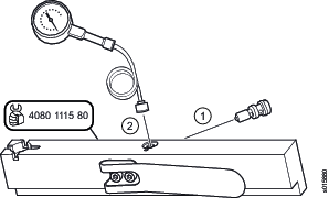
Leak test
If the valve is attached to the tool, remove it . Use the fork-shaped tool (4080 1114 00) and turn it clockwise.
Insert the valve in the connector (1) of the test tool and tighten it to 0.7 Nm. See the figure below.
Connect an air hose to the connector (2).
Press the tool lever two to three times to supply the air pressure of 6.3 bar (90 psi).
Measure the leakage with a leakage meter. Air leakage during 10 seconds must be less than 0.3 l/min.
If the result of the test is unsatisfactory, replace the valve. If the test shows no fault, continue the procedure.
Install the valve in the original position and tighten it with the fork-shaped tool to 0.7 Nm.
Recycling
Environmental Regulations
When a product has served its purpose it has to be recycled properly. Dismantle the product and recycle the components in accordance with local legislation.
Batteries shall be taken care of by your national battery recovery organization.