LBV11 S029-S90
Angle drill
Product Information
General Information
Safety Signal Words
The safety signal words Danger, Warning, Caution, and Notice have the following meanings:
DANGER | DANGER indicates a hazardous situation which, if not avoided, will result in death or serious injury. |
WARNING | WARNING indicates a hazardous situation which, if not avoided, could result in death or serious injury. |
CAUTION | CAUTION, used with the safety alert symbol, indicates a hazardous situation which, if not avoided, could result in minor or moderate injury. |
NOTICE | NOTICE is used to address practices not related to personal injury. |
Warranty
Product warranty will expire in 12+1 months after dispatch from Atlas Copco's Distribution Center.
Normal wear and tear on parts is not included within the warranty.
Normal wear and tear is that which requires a part change or other adjustment/overhaul during standard tool maintenance typical for that period (expressed in time, operation hours or otherwise).
The product warranty relies on the correct use, maintenance, and repair of the tool and its component parts.
Damage to parts that occurs as a result of inadequate maintenance or performed by parties other than Atlas Copco or their Certified Service Partners during the warranty period is not covered by the warranty.
To avoid damage or destruction of tool parts, service the tool according to the recommended maintenance schedules and follow the correct instructions.
Warranty repairs are performed only in Atlas Copco workshops or by Certified Service Partners.
Atlas Copco offers extended warranty and state-of-the-art preventive maintenance through its ToolCover contracts. For further information, contact your local Service representative.
For electrical motors:
Warranty will apply, only when the electric motor has not been opened.
Website
Information concerning our Products, Accessories, Spare Parts and Published Matters can be found on the Atlas Copco website.
Please visit: www.atlascopco.com.
ServAid
ServAid is a portal that is continuously updated and contains Technical Information, such as:
Regulatory and Safety Information
Technical Data
Installation, Operation and Service Instructions
Spare Parts Lists
Accessories
Dimensional Drawings
Please visit: https://servaid.atlascopco.com.
For further Technical Information, please contact your local Atlas Copco representative.
Safety Data Sheets MSDS/SDS
The Safety Data Sheets describe the chemical products sold by Atlas Copco.
Please consult the Atlas Copco website for more information www.atlascopco.com/sds.
PTFE
Country of Origin
For the Country of Origin, please refer to the information on the product label.
Dimensional Drawings
Dimensional Drawings can be found either in the Dimensional Drawings Archive, or on ServAid.
Please visit: https://webbox.atlascopco.com/webbox/dimdrw or https://servaid.atlascopco.com.
Overview
Applications
This is a drill used for all applications and industry segments.
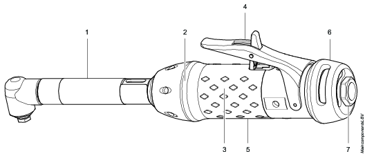
Main components and functions
This product, its attachments and accessories are intended to be used for drilling, reaming, and countersinking.
|
Pos |
Component |
Function |
|---|---|---|
|
1 |
Angle head complete |
Transfers the rotation from the air motor to the drill spindle. |
|
2 |
Gear unit |
Gears up the torque from the air motor. |
|
3 |
Lubrication free air motor |
Gives a cleaner working environment. |
|
4 |
Trigger |
Starts the drill with slow start function. |
|
5 |
Handle |
Gives a comfortable rubber grip. |
|
6 |
Adjustable air exhaust |
Guides the cool air away from the operator. |
|
7 |
Inlet adapter |
Connects the drill to the air preparation unit (pressurized air). |
Technical Product Data
Technical Product Data can be found on either ServAid, or the Atlas Copco website.
Please visit: https://servaid.atlascopco.com or www.atlascopco.com.
If the Technical Product Data is not available on either website, please contact the local Atlas Copco Customer Center for assistance.
Accessories
Required Accessories
Safety Lever Kit
Use the safety lever kit if the tool is not provided with an inbuilt safety lever.
The safety lever comes as a spare part. (Ordering number - 4110 1787 81)
For further information contact your local Atlas Copco representative.
Service Overview
Preventive maintenance
Make sure to do a preventive maintenance every 6 months. If it is used in heavy duty conditions or not running correctly, it should be removed from operation for inspection more often.
Use detergents containing isopropanol or acetone for cleaning tool surfaces of rubber, for example the handle. Do not use MPK (Methyl Propyl Ketone) solvent.
Installation
Installation Requirements
Air Quality
For optimum performance and maximum product life we recommend the use of compressed air with a maximum dew point of +10°C (50°F). We also recommend to install an Atlas Copco refrigeration type air dryer.
Use a separate air filter which removes solid particles larger than 30 microns and more than 90% of liquid water. Install the filter as close as possible to the product and prior to any other air preparation units to avoid pressure drop.
For impulse/impact tools make sure to use lubricators adjusted for these tools. Regular lubricators will add too much oil and therefore decrease the tool performance due to too much oil in the motor.
Make sure that the hose and couplings are clean and free from dust before connecting to the tool.
Both lubricated and lubrication free products will benefit from a small quantity of oil supplied from a lubricator.
Air Lubrication Guide
Recommended air lubricators:
Atlas Copco Optimizer (1 liter) 9090 0000 04
Q8 Chopin 46
Q8 Chopin 32
Shell Air Tool Oil S2 A 320
Mobil SHC Cibus 32
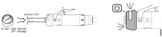
Compressed Air Connection
For correct air pressure and hose size, see the Technical Product Data on - https://servaid.atlascopco.com or www.atlascopco.com.
Make sure that the hose and couplings are clean and free from dust before connecting to the tool.
Installation Instructions
Installing the drill

Position the support handle for either right- or left handed operation.
Drain the hose of air pressure before connecting to air supply.
Tighten the drill bit in place with a chuck. A keyed chuck uses a rotary key to tighten and loosen the chuck. A keyless chuck is operated by hand.

Never drill a hole that is larger than the rated capacity for the drill.
The motor requires no additional lubrication during operation.
Connect the tool to the air supply.
Use the appropriate drilling speed for the application.
To start the tool, press the trigger.
When lubrication is recommended - only use lubricants recommended by Atlas Copco.
Operation
Ergonomic Guidelines
Consider your workstation as you read through this list of general ergonomic guidelines to identify areas for improvement in posture, component placement, or work environment.
Take frequent breaks and change work positions frequently.
Adapt the workstation area to your needs and the work task.
Adjust for a convenient reach range by determining where parts and tools need to be located to avoid static load.
Use workstation equipment such as tables and chairs appropriate for the work task.
Avoid work positions above shoulder level or with static holding during assembly operations.
When working above shoulder level, reduce the load on the static muscles by lowering the weight of the tool, using for example torque arms, hose reels or weight balancers. You can also reduce the load on the static muscles by holding the tool close to the body.
Take frequent breaks.
Avoid extreme arm or wrist postures, particularly during operations requiring a degree of force.
Adjust for a convenient field of vision that requires minimal eye and head movements.
Use appropriate lighting for the work task.
Select the appropriate tool for the work task.
In noisy environments, use ear protection equipment.
Use high-quality inserted tools and consumables to minimize exposure to excessive levels of vibration.
Minimize exposure to reaction forces.
When cutting:
A cut-off wheel can get stuck if the cut-off wheel is bent or not guided properly. Always use the correct flange for the cut-off wheel and avoid bending the cut-off wheel during operation.
When drilling:
The drill might stall when the drill bit breaks through. Use support handles if the stall torque is high. The safety standard ISO11148 part 3 recommends using a device to absorb a reaction torque above 10 Nm for pistol grip tools and 4 Nm for straight tools.
When using direct-driven screwdrivers or nutrunners:
Reaction forces depend on the tool settings and joint characteristics. Strength and posture determine the amount of reaction force that an operator can tolerate. Adapt the torque setting to the operator's strength and posture and use a torque arm or reaction bar if the torque is too high.
In dusty environments, use a dust extraction system or wear a mouth protection mask.
Operating Instructions
Throttle Lever with Safety Trigger
The purpose of a throttle lever with safety trigger is to avoid unintentional start of the tool.
Flip the safety trigger to lock/unlock the safety function. Always put the throttle lever in locked position before putting away the tool.
Make sure that the safety trigger works correctly.
Replace the throttle lever if it does not work correctly.
Never remove the safety trigger or lock it with tape.
Operating the drill
-
Use the approriate drill for the application.
-
Tighten the drill bit in place with a chuck. A keyed chuck uses a rotary key to tighten and loosen the chuck. A keyless chuck is operated by hand.
-
Remove the rotary key before starting the tool.
-
Make sure the workpiece is securely fixed.
-
Always have a firm footing when drilling. Brace and position yourself carefully when drilling.
-
Always make sure there are no electrical wires or water lines behind the surface you are drilling into.
Never drill a hole that is larger than the rated capacity for the drill.
-
Use the appropriate drilling speed for the application.
-
Start the tool by pressing the trigger.
-
Do not force the drill. If the drill slows down, change to a drill with more power, so that the drill bit can continue cutting smoothly.
-
If the drill gets caught in the material, release the trigger immediately, unplug the drill and remove the bit from the material.
When lubrication is recommended - only use lubricants recommended by Atlas Copco.
Service
Maintenance Instructions
Installation
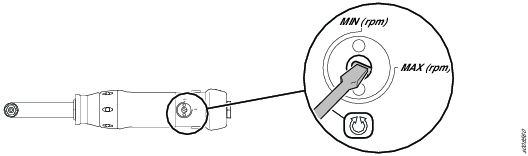
Adjustable exhaust
Service Recommendations
Preventive maintenance is recommended at regular intervals. See the detailed information on preventive maintenance. If the product is not working properly, take it out of service and inspect it.
If no detailed information about preventive maintenance is included, follow these general guidelines:
Clean appropriate parts accurately
Replace any defective or worn parts
Preventive maintenance
Make sure to do a preventive maintenance every 6 months. If it is used in heavy duty conditions or not running correctly, it should be removed from operation for inspection more often.
Use detergents containing isopropanol or acetone for cleaning tool surfaces of rubber, for example the handle. Do not use MPK (Methyl Propyl Ketone) solvent.
Overhaul and lubrication
The tool should be checked regularly at six-monthly intervals. If it is in heavy duty service or not running properly, it should be taken out of service more often for inspection.
Regarding instruction for dismantling and assembly, see separate Service Manual.
The throttle valve, planetary gears, needle bearings and ball bearings must be lubricated with grease when the tool is dismantled for the regular overhauls. Molykote BR2 Plus gives long intervals between lubrications.
Clean the motor parts and apply a thin layer of air lubrication
oil onto the vanes and inner surface of cylinder and end plates.
Assemble
the motor and check that it is running free. Add two drops of oil
through the air inlet and run the motor (machine) at idling speed
for 5-10 seconds.
The strainer in the adapter should be cleaned regularly to prevent choking with resultant decrease in capacity
Free speed
Modell | Max speed (r/min, rpm) |
LBV11 S029-S90 | 2900 |
Lubrication Instructions
Rust Protection and Cleaning
Water in the compressed air can cause rust. To prevent rust we strongly recommend to install an air dryer.
Water and particles can cause sticking of vanes and valves. This can be prevented by installing an air filter close to the product to avoid pressure drop.
Before longer standstills always protect your tool by adding a few drops of oil into the air inlet. Run the tool for 5–10 seconds and absorb any access oil at the air outlet in a cloth.
Lubrication Guide
|
Brand |
General purpose, Bearings and Gears* |
|---|---|
|
BP |
Energrease LS-EP2 |
|
Castrol |
OBEEn UF 1 |
|
Esso |
Beacon EP2 |
|
Q8 |
Rembrandt EP2 |
|
Mobil |
Mobilegrease XHP 222 NLG 2 |
|
Klüber Lub. |
Klübersynth UH 1 14-151 |
|
Texaco |
Multifak EP2 |
|
Molykote |
BR2 Plus |
* Not for angle gears.
|
Brand |
Angle gears |
|---|---|
|
Molykote |
Longterm 2 Plus |
Maintenance and lubrication
The throttle valve, planetary gears, needle bearings and ball bearings must be lubricated with grease when the tool is dismantled at the regular maintenance. Molycote BR2 Plus gives long intervals between lubrications.
-
Dismantle the motor, see the Dismantling and assembly section.
-
Clean the motor parts and apply a thin layer of air lubrication oil onto the vanes and inner surface of cylinder and end plates.
-
Assemble the motor and make sure that it is running free. Add two drops of oil through the air inlet and run the motor at idling speed for 5-10 seconds.
The strainer in the adapter should be cleaned regularly to prevent choking which will lead to a loss in capacity.
Dismantling/Assembling Instructions
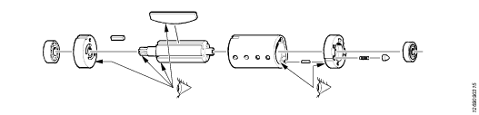
Instructions for Vane Motors
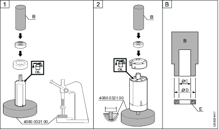
Dismantling
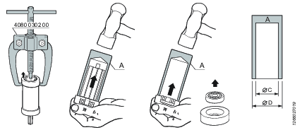
Service tools are also included in the Basic Service Tools set. For further information see ordering No. 9835 5485 00
Dismantling tool Mandrel A
Ordering No. | Ø D | Ø C |
|---|---|---|
4080 0182 01 | 7 | 3.5 |
4080 0182 02 | 8 | 4.5 |
4080 0182 03 | 9 | 5.5 |
4080 0182 04 | 10 | 6.5 |
4080 0182 05 | 13 | 8.5 |
4080 0182 06 | 16 | 10.5 |
4080 0182 07 | 19 | 12.5 |
4080 0182 08 | 22 | 15.5 |
4080 0182 09 | 24 | 17.5 |
4080 0182 10 | 26 | 20.5 |
4080 0182 11 | 30 | 25.5 |
4080 0182 12 | 35 | 30.5 |
4080 0182 13 | 40 | 35.5 |
4080 0182 14 | 47 | 40.5 |
Inspection of motor parts
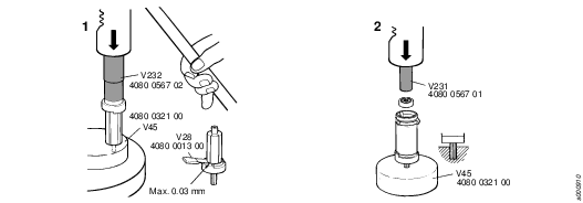
Assembling
Service tools are also included in the Basic Service Tools set. For further information see ordering No. 9835 5485 00
Dismantling tool Mandrel B
Ordering No. | Ø D | Ø C |
|---|---|---|
4080 0567 04 | 12.5 | 5.2 |
4080 0567 11 | 14.5 | 6.5 |
4080 0567 01 | 15.5 | 5.2 |
4080 0567 05 | 18.5 | 6.2 |
4080 0567 02 | 18.5 | 8.2 |
4080 0567 06 | 21.5 | 7.5 |
4080 0567 03 | 21.5 | 8.2 |
4080 0567 07 | 25.5 | 10.5 |
4080 0567 08 | 27.5 | 12.5 |
4080 0567 09 | 31.5 | 15.5 |
4080 0567 10 | 34.5 | 18.5 |
Assembly of vane motor according to Bäckströms method
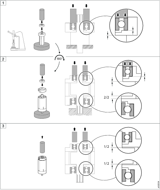
Assembly of motor
Troubleshooting
Troubleshooting
The table describes the most common problems, possible reasons and how to fix them. Note that some actions must be carried out by authorized workshops or qualified service technicians.
Problem | Possible reason | Action |
|---|---|---|
Free speed is too slow, pressure never reaches the target. | Too low air flow in the pressurized air system. | Shorter hose to the FRL unit and/or larger diameter is needed. See Installation proposal for more information. |
The tool has been in contact with water. | The pressurized air system contains condensed water. | See Service recommendations for specific environments. |
The tool does not start. | No air flow to the tool. | Make sure that the air connection is correctly set. |
| Motor jammed. | * |
Inconsistent idling speed. | Unstable air pressure. | Make sure that the air pressure regulator is working correctly. |
| Worn governor (LBB45). | * |
Low power | Low air pressure. | Make sure that the air pressure is correctly set. |
| Wrong lenght or dimension of air supply hose. | Make sure that the air connection is correctly set. |
| Blocked filters. | Clean or change the corse and fine filter |
| The humidity in the air is high. | Make sure that the compressor is working correctly. |
| Too much grease in the gear box. | Make sure that the amount of grease is correct. |
| Worn throttle valve | * |
| Worn vanes/motor? | * |
| Worn governor (LBB45) | * |
Tool starts unexpectedly | Damaged throttle valve | * |
| Valve pin jammed in start position. | Change pin and guide |
Vibrations | Worn or damage drill bit. | Change drill bit |
The motor housing istoo hot. | Too much grease in the gear box. | Make sure that the amount of grease is correct. |
Abnormal sound | Not enough grease in gear housing. | Make sure that the amount of grease is correct. |
| Damaged gear. | * |
| Worn motor bearings. | * |
*) This service must only be carried out by authorized workshop or qualified service technician.
Recycling
Environmental Regulations
When a product has served its purpose it has to be recycled properly. Dismantle the product and recycle the components in accordance with local legislation.
Batteries shall be taken care of by your national battery recovery organization.
Recycling information
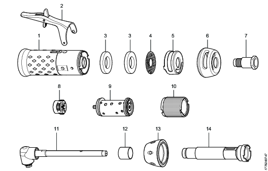
| Part: | Recycle as: |
|---|---|---|
1 | Handle | Metal, Aluminum |
2 | Trigger | Metal, Steel |
3 | Silencer | Viledon |
4 | Silencer | Metal, Steel |
5 | Deflector | Plastics, PA GF30 |
6 | Air distributor | Plastics, PA GF30 |
7 | Adapter | Metal, Steel |
8 | Gear | Metal, Steel |
9 | Vane motor | Metal, Steel* |
10 | Gear rim | Metal, Steel |
11 | Angle head | Metal, Steel |
12 | Code ring | Plastics, PPCO |
13 | Nut | Metal, Aluminum |
14 | Extension | Metal, Steel |
*The rotor blades (vanes) in the tool contains PTFE, the normal health and safety recommendations concerning PTFE must be observed.