Product Information
General Information
Safety Signal Words
The safety signal words Danger, Warning, Caution, and Notice have the following meanings:
DANGER | DANGER indicates a hazardous situation which, if not avoided, will result in death or serious injury. |
WARNING | WARNING indicates a hazardous situation which, if not avoided, could result in death or serious injury. |
CAUTION | CAUTION, used with the safety alert symbol, indicates a hazardous situation which, if not avoided, could result in minor or moderate injury. |
NOTICE | NOTICE is used to address practices not related to personal injury. |
Warranty
Product warranty will expire 12 months after the product is first taken into use, but will in any case expire at the latest 13 months after delivery.
Normal wear and tear on parts is not included within the warranty.
Normal wear and tear is that which requires a part change or other adjustment/overhaul during standard tools maintenance typical for that period (expressed in time, operation hours or otherwise).
The product warranty relies on the correct use, maintenance, and repair of the tool and its component parts.
Damage to parts that occurs as a result of inadequate maintenance or performed by parties other than Atlas Copco or their Certified Service Partners during the warranty period is not covered by the warranty.
To avoid damage or destruction of tool parts, service the tool according to the recommended maintenance schedules and follow the correct instructions.
Warranty repairs are only performed in Atlas Copco workshops or by Certified Service Partners.
Atlas Copco offers extended warranty and state of the art preventive maintenance through its ToolCover contracts. For further information contact your local Service representative.
For electrical motors:
Warranty will only apply when the electric motor has not been opened.
Website
Information concerning our Products, Accessories, Spare Parts and Published Matters can be found on the Atlas Copco website.
Please visit: www.atlascopco.com.
ServAid
ServAid is a portal that is continuously updated and contains Technical Information, such as:
Regulatory and Safety Information
Technical Data
Installation, Operation and Service Instructions
Spare Parts Lists
Accessories
Dimensional Drawings
Please visit: https://servaid.atlascopco.com.
For further Technical Information, please contact your local Atlas Copco representative.
Safety Data Sheets MSDS/SDS
The Safety Data Sheets describe the chemical products sold by Atlas Copco.
Please consult the Atlas Copco website for more information www.atlascopco.com/sds.
Country of Origin
For the Country of Origin, please refer to the information on the product label.
Dimensional Drawings
Dimensional Drawings can be found either in the Dimensional Drawings Archive, or on ServAid.
Please visit: http://webbox.atlascopco.com/webbox/dimdrw or https://servaid.atlascopco.com.
Overview
Applications
This high-quality, easy-to-handle pneumatic Positive Feed Drill (PFD) can be used for drilling holes in various metals and composites.
Main components and functions
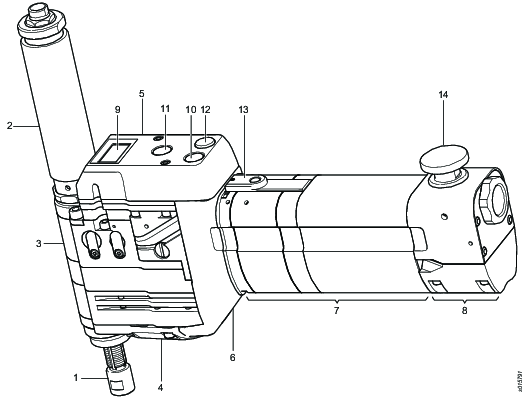
Pos | Component | Function |
|---|---|---|
1 | Spindle | Main rotating part of the drill. |
2 | Spindle guard | Protects the operator from the rotating spindle. Provides the drill bit with coolant. |
3 | Head | Transfers rotational torque and feed from the motor to the spindle. |
4 | Feed cassette | Defines spindle feed rate. Measured in inches per revolution (IPR) or millimeters per revolution (mm/rev). |
5 | Air logic | Operates the drill. |
6 | Split gear | Defines rotational speed. Measured in revolutions per minute (RPM). |
7 | Motor housing | Supplies power and rotation to the spindle. Defines PRM range. |
8 | Motor valve | Supplies airflow to the turbine motor. |
9 | Counter | Counts number of drilled holes (optional). |
10 | Start button | Starts the motor and activates the drill feed and rotation mechanism. The motor continues to run after the button is released. When the spindle reaches the pre-defined drilling depth, it returns automatically to the starting position and the motor switches off. |
11 | Retract button | Returns the spindle to the starting position at any time during the drilling cycle. The motor switches off automatically after retract. |
12 | Release button | Releases the concentric collet foot or the indexer (air-powered front part). Applicable only if the front part is installed. |
13 | Pause button | Stops the drill momentarily. The drill cycle continues after pressing the start button. The pause button is also used when setting up the drill and the drill depth. |
14 | Emergency stop button | Switches off air supply to the motor and stops the spindle at any time during drilling cycle. Once pressed, the emergency stop button locks in position. Disconnects the drill from the air supply before you manually resets the emergency stop button. Connects the drill to the air supply and restarts the drill. |
Technical Product Data
Technical Product Data can be found on either ServAid, or the Atlas Copco website.
Please visit: https://servaid.atlascopco.com or www.atlascopco.com.
Accessories
Overview accessories
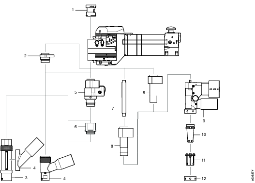
Pos | Component |
|---|---|
1 | ChipLet |
2 | Adapter |
3 | Front part |
4 | Vacuum |
5 | Indexer |
6 | Extension |
7 | Guide |
8 | Guide bushing |
9 | Concentric collet foot |
10 | Mandrel |
11 | Collet |
12 | Lock nut |
For detailed information of accessories, refer to ServAid.
Speed
A split gear can be set in two different positions in relation to the motor housing of the drill. By turning the split gear 180 degrees you can change the speed, as shown in the figure below. For further information, please see section “Changing the speed”.

Markings on the split gear housing indicate ratios. The markings, on the split gear housing closest to the motor housing of the drill, indicate the actual ratio. See the figure below.

The combination of motor housing, split gear and head determines the speed of the drill spindle. Select from the available combinations of motor housings, split gears and heads in the table below to get the desired RPM.
Motor housing | Split gear | Head | |
|---|---|---|---|
RPM | Ordering No. | Ordering No. | Ordering No. |
220 | 4141 0888 90 | 4141 0432 94 | 4141 0401 92 |
350 | 4141 0452 93 | 4141 0432 94 | 4141 0401 92 |
430 | 4141 0452 93 | 4141 0432 95 | 4141 0401 92 |
520 | 4141 0452 93 | 4141 0432 91 | 4141 0401 92 |
700 | 4141 0452 93 | 4141 0432 92 | 4141 0401 92 |
930 | 4141 0452 93 | 4141 0432 93 | 4141 0401 92 |
1200 | 4141 0452 93 | 4141 0432 93 | 4141 0401 92 |
1600 | 4141 0452 93 | 4141 0432 92 | 4141 0401 92 |
2200 | 4141 0452 93 | 4141 0432 91 | 4141 0401 92 |
2600 | 4141 0452 93 | 4141 0432 95 | 4141 0401 92 |
3200 | 4141 0452 93 | 4141 0432 94 | 4141 0401 92 |
4200 | 4141 0452 94 | 4141 0432 92 | 4141 0401 93 |
5500 | 4141 0452 94 | 4141 0432 93 | 4141 0401 93 |
7300 | 4141 0452 94 | 4141 0432 93 | 4141 0401 93 |
Starting position and drilling depth
Using stop rings, you can define the following parameters:
Starting position of the drill bit
Drilling depth

Pos | Part | Function |
|---|---|---|
1 | Starting position ring | Defines the starting position for drilling. This allows for quick positioning of the drill bit at the pre-defined safe distance to the surface. The starting position can be adjusted. |
2 | Starting position | Controls the starting position for drilling. Once the starting position ring reaches the disc spring at home position, the motor switches off. NOTE: If the starting position ring is not used, the motor switches off when the lowest part of the spindle reaches the disc spring at home position. |
3 | Depth ring | Defines the drilling depth. |
4 | Depth position | Controls the drilling depth. Once the depth ring reaches the stop surface, the spindle retracts into the starting position. The motor automatically switches off after retract. |
Calculate the drilling depth

You can calculate the distance between the depth ring and the drill head (dimension L in the figure) for the desired stroke D according to the following formula:
L (mm) =D (mm) + 24.95 mm
L (in) = D (in) + 0.98 in
Counter
Overview

Pos | Part | Function |
|---|---|---|
A | Display | Displays values and settings. |
B | Switch left (SW-L) | Sets values or settings. Shows the information on the display and is also used with the button SW-R to change values or settings. |
C | Red-yellow LED | Shows alarms. |
D | Magnetic switch right (SW-R) | Changes values or settings. Activates with a magnet and is used with the button SW-L. |
E | Green LED | Shows alarms. |
Battery
Use battery CR2450N.
User mode
The following information displays when you press the button SW-L. To change between the information, press the button while showing the previous information.
Code | Information |
|---|---|
CNT TOOL | Numbers of drilled holes with the drill bit. It is counting down from a set value. |
CNT SERV | Numbers of drilled holes with the PFD. It is counting down from a set value. |
DRL DLAY | Seconds for the drill to move before the counter detects it as a drilled hole. Delays the PFD if it has a rapid advance function, otherwise the counter will count the rapid advance move as a drilled hole. |
CNT GLOB | Total drilled holes with the PFD. Counting up. |
CNT TIME | Number of hours of drilling with the PFD. |
VAL TOOL MX | Programmed values of maximum drilled holes with the drill bit. It is from this value the CNT TOOL is counting down. |
VAL SERV MX | Programmed values of maximum drilled holes with ADU before maintenance. It is from this value the CNT SERV is counting down. |
ALM TOOL | Alarm value, 6% of the numbers programmed for tool. The value where the counter sets off an alarm that it is time to change the drill bit. |
ALM SERV | Alarm value, 6% of the numbers programmed for ADU maintenance. The value where the counter sets off an alarm that it is time to change ADU. |
BATTERY VOLTAGE | The percentage of the battery that is left. Minimum 1.9 V. |
Changing setting and value
To change settings and values for the counter both the buttons SW-L and SW-R are to be used.
To enter the settings mode press the button SW-L and simultaneously hold a magnet over the button SW-R . After that use the button SW-L to go through the values that can be changed and to modify digits. The button SW-R is used as an OK and next button (it has to be made within a few seconds). This is also seen at the bottom of the display.
Code used to modify values | Being modified |
|---|---|
RST TOOL | Resets the counter CNT TOOL and clears alarms. |
RST SERV | Resets the counter CNT SERV and clears alarms. |
PRG TOOL | Programs value VAL TOOL MX for CNT TOOL. |
PRG SERV | Programs value VAL TOOL MX for CNT SERV. |
PRG DLY | Programs DRL DLAY. |
REPL BAT | Safeguards the counter before battery replacement. |

Alarm
The following alarms can be seen on the counter LEDs, red-yellow and green.
Green LED | Yellow LED | Red | Signification of alarms |
|---|---|---|---|
Flash | Drilling detected. | ||
Flash | Flash | Warning concerning a less than 6% for ALM TOOL or ALM SERV during a drilling. | |
Flash | Warning concerning a less than 6% for ALM TOOL or ALM SERV. | ||
Flash | Flash | The limits of CNT TOOL or CNT SERV are exceeded during a drilling. | |
Flash | The limits of CNT TOOL or CNT SERV are exceeded. | ||
Flash | Flash | Flash | Low battery during a drilling. |
Flash | Flash | Low battery. | |
Fast flash | Replacement battery needed. |
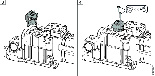
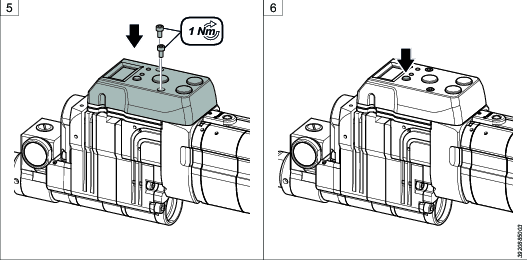
Installing the counter
Required tools
Torx key
Remove the screws that fasten the air logic cover using an Allen key.
Remove the cover.
Connect the cable to the contact on the back of the counter.
Put the distances between the counter and the air logic. Install the counter and tighten it with the screws using a Torx key.

Make sure the cable is not squeezed.
Put the air logic cover back into original position and tighten the cover with the screws using an Allen key.
Press the button SW-L to begin using the counter.

Feed rate
Normally a feed cassette can define two different feed rates. By turning the feed cassette 180 degrees you can change the feed rates, as shown in the figure below. The feed rate of the drill must be balanced with the spindle speed. Select from the available combinations of feed rates in the table below to get the desired feed rate.


|
Feed cassette | ||
|---|---|---|
|
IPR |
mm/rev |
Ordering No. |
|
0.0007 |
0.017 |
4141 0428 95 |
|
0.0011 |
0.028 |
4141 0428 91 |
|
0.0015 |
0.038 |
4141 0428 96 |
|
0.0021 |
0.054 |
4141 0428 97 |
|
0.0028 |
0.071 |
4141 0428 93 |
|
0.0037 |
0.093 |
4141 0428 94 |
|
0.0045 |
0.115 |
4141 0428 93 |
|
0.0052 |
0.13 |
4141 0428 97 |
|
0.0059 |
0.15 |
4141 0428 96 |
|
0.0064 |
0.16 |
4141 0428 91 |
|
0.0068 |
0.17 |
4141 0428 95 |
Service Overview
Service Recommendations
Preventive maintenance is recommended at regular intervals. See the detailed information on preventive maintenance. If the product is not working properly, take it out of service and inspect it.
If no detailed information about preventive maintenance is included, follow these general guidelines:
Clean appropriate parts accurately
Replace any defective or worn parts
Maintenance intervals
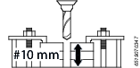
One cycle is calculated on a standard stack of 10 mm.
Heavy Usage | Medium Usage | Light Usage | |||||
|---|---|---|---|---|---|---|---|
Cycles | Total drilling length (meter) | Action | Spare part | Use kit, | Use kit, | Use kit, | |
a Independent from the drilling thickness | |||||||
10,000 | 100 | Replace | Bevel gear | 4141 0410 91 | |||
20,000 | 200 | Replace | Chiplet | 4141 0713 9X | |||
Ratcheta | 4141 0713 9X | ||||||
25,000 | 250 | Replace | Ratcheta | 4141 0713 9X | 4141 0713 9X | ||
50,000 | 500 | Replace | Bevel gear | 4141 0410 91 | |||
Thrust bearing | 4141 0509 91 | ||||||
Chiplet | 4141 0713 9X | ||||||
Piston | 4081 0496 90 | 4081 0496 90 | 4081 0496 90 | ||||
Re-grease | Planetary shaft | Grease (Type A) | Grease (Type A) | N/A | |||
Overload clutcha | Grease (Type A) | Grease (Type A) | Grease (Type A) | ||||
100,000 | 1000 | Replace | Bevel gear | 4141 0410 91 | |||
Thrust bearing | 4141 0509 91 | 4141 0509 91 | |||||
Chiplet | 4141 0713 9X | ||||||
Planetary shaft | 4141 0444 90 | ||||||
Overload clutcha | 4141 0498 92 | 4141 0498 92 | 4141 0498 92 | ||||
200,000 | 2000 | Replace | Planetary shaft | 4141 0444 90 | |||
The drilling operation may produce different efforts (torque, thrust) than the estimated value due to different cutting tools geometry, material properties or lubrication. Therefore, the same operation can be categorized differently.
Heavy Usage | Medium Usage | Light Usage | |
|---|---|---|---|
Rotational speed and Drilling efforts | Speed 350-1200 rpm
| Speed 1600-3200 rpm | Speed 3200-7300 rpm |
Example of operations |
|
|
|
Installation
Installation Requirements
Air quality
Poor air quality may cause damage to the tool and reduce the performance.
For optimum performance and maximum product life we recommend the use of compressed air with a maximum dew point of -5°C (23°F). We also recommend to install an Atlas Copco refrigeration type air dryer.
Use a separate air filter which removes solid particles larger than 30 microns and more than 90% of liquid water. Install the filter as close as possible to the tool and prior to any other air preparation units to avoid pressure drop.
Lubrication free tools are a better choice from an environmental perspective.
We recommend to use the tool with oil-free air. In case you need to use lubricated air, we strongly recommend that you install an Atlas Copco oil-fog lubricator (DIM). This should be set with maximum of 20 drops per min (1 drop = 15 mm3). A single point lubricator type Atlas Copco Dosol can also be used for tools with short running cycles. Information about Dosol settings may be found under Air Line Accessories in our main catalogue.
For maximum product life, once the tool has been operated with air containing oil, it is not recommended to switch to oil-free air again.
Air Lubrication Guide
Brand | Air lubrication |
|---|---|
Atlas Copco | Optimizer (1 liter) 9090 0000 04 |
Q8 | Chopin 46 |
Shell | Shell Air Tool Oil S2 A 320 |
Compressed Air Connection
For correct air pressure and hose size, see the Technical Product Data on - https://servaid.atlascopco.com or www.atlascopco.com.
Make sure that the hose and couplings are clean and free from dust before connecting to the tool.
Installation Instructions
Installing the drill
Required tools
-
Vise
-
Open-end spanners
-
Allen key
-
Fasten the drill in a vise with rubber pads, with the air logic unit downward and the drill handle to the right.
-
If applicable, install the starting position ring onto the spindle and move it into position. Tighten the starting position ring using an Allen key.
-
Install the spindle in the spindle socket from above. Turn the spindle counterclockwise to feed the spindle using an open-end spanner.
-
Put the drill bit in the spindle. Place open-end spanners on the spindle socket and the drill bit base to keep them from rotating. Tighten the connection. Put the front part over the drill bit. Turn the front part counterclockwise to secure it onto the connector.
-
Loosen the drill and turn it over. Fasten the drill in the vise.
-
Install the depth ring onto the spindle and move it into position. Tighten the depth ring using two open-end spanners.
-
Put the spindle guard over the spindle. Secure the spindle guard using an open-end spanner.
-
Attach a nipple for an air hose to the connector on the side of the motor valve. Connect the air hose to the nipple. Do a functional test of the emergency stop button:
-
Push the start button.
-
Push the emergency stop button so that it locks in position. The air supply to the motor switches off and the spindle stops.
-
Disconnect the air hose.
-
Pull the emergency stop button to reset it.
-


Changing the spindle
Required tools
-
Vise
-
Open-end spanners
-
Allen key
-
Fasten the drill in a vise with rubber pads, with the spindle guard upward and the drill handle to the right. Remove the spindle guard using an open-end spanner.
-
Remove the depth ring from the spindle using two open-end spanners.
-
Loosen the drill and turn it over. Fasten the drill in the vise.
-
Remove the front part and the drill bit using open-end spanners.
-
Turn the spindle clockwise to remove it using an open-end spanner.
-
If applicable, remove the starting position ring using an Allen key.
-
Do steps 2 to 8 in the section “Installing the drill”.


Installing the indexing stop nut
With the indexing stop nut, the product is adapted for drilling and countersinking a hole with high precision in a single operation.
Required tools
-
Vise
-
Open-end spanner
-
Fasten the drill in a vise with rubber pads.
-
Remove the spindle guard from the spindle.
-
Remove the depth ring from the spindle using an open-end spanner.
-
Install the indexing stop nut onto the spindle by hand.
Note that there are 4 metal lugs inside the nut. These lugs need to be eased into the 4 corresponding grooves on the spindle when attaching the nut.

Installing the ChipLet
Required tools
-
Vise
-
Open-end spanners
-
Allen key
-
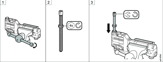
Fasten the drill in a vise with rubber pads, with the spindle guard upward and the drill handle to the right. Remove the spindle guard using an open-end spanner.
-
Remove the depth ring from the spindle using two open-end spanners.
-
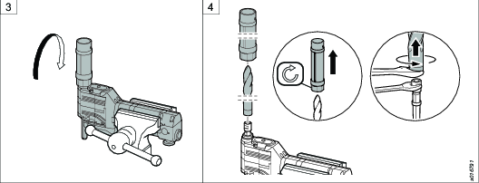
Remove the cover in front of the ratchet using an Allen key. Fasten a screw in the ratchet and pull the ratchet out.
-
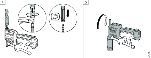
Remove the thrust bearing from the drill using an Allen key.
-
Replace the thrust bearing with a ChipLet. Tighten the ChipLet using an Allen key.
-
Put the ratchet back in original position. Put the cover in front of the ratchet and tighten the cover with the screw.
-
Do steps 6 to 8 in the section “Installing the drill”.


Installing the concentric collet
Required tools
-
Vise
-
Open-end spanners
-
Hook wrench
-
Allen key
-
Fasten the drill in a vise with rubber pads, with the spindle guard upward and the drill handle to the right. Remove the spindle guard using an open-end spanner.
-
Remove the depth ring from the spindle using two open-end spanners.
-
Remove the screws that secure the connector.
-
If applicable, remove the connector and the front part.
Do not loose the disc springs.
-
Turn the spindle clockwise to feed out the spindle using an open-end spanner.
-
Replace the old spindle with a spindle for concentric collet. Turn the spindle counterclockwise to feed the spindle using an open-end spanner.
-
Put the drill guide on the spindle. Tighten the drill guide using an open-end spanner.
-
Put the drill bit in the drill guide. Tighten the drill bit using an open-end spanner.
-
Put the guide bushing over the drill guide. Tighten it with screws using an Allen key.
Make sure the disc springs are put in correct position.
-
Install the depth ring onto the spindle and move it into position. Tighten the depth ring using two open-end spanners.
-
Loosen the drill and turn it over. Fasten the drill in the vise.
-
Remove the cap nut from the concentric collet using a hook wrench. Put the concentric collet over the guide bushing. Tighten the concentric collet to the guide bushing using an Allen key.
-
Put the mandrel over the drill bit. Tighten it on the concentric collet using a socket.
-
Put the collet over the mandrel. If the collet is put in correct position, the flanges on the collet will now fit into the slots on the mandrel and prevent it from turning.
Install the cap nut on the concentric collet. Tighten it using a hook wrench.


Calibrating the position of the indexing stop nut
Required tools
-
Vise
-
Open-end spanner
-
Place the indexing stop nut roughly in position, and perform drill test holes to decide a more exact position.
Always tighten the upper nut before a test hole is drilled.
-
Make the final adjustments to the position by turning the lower part of the nut.
When making the final adjustments, the upper nut should be tightened lightly by hand. For each adjustment of 0.02 mm, a "click" is felt when turning the lower nut.
-
When the position is correct, tighten the upper locking nut.

Installing the indexer
Required tools
-
Allen key
Make sure the following components are removed from the drill:
-
Spindle cover
-
Front part
-
Drill bit
-
Remove the connector using an Allen key.
-
Replace the connector with the indexer and put it in position. Tighten the index with an Allen key.
Put the above components back after finishing the installation.

Assembling swiveling front part
Required tools
Opening plier
Open-end spanner
Hook wrench
For the parts that use regular indexer:
Remove the locking washer from the front part.
Slide the vacuum attachment onto the front part.
Attach the locking washer back to the groove on the front part.

For the parts that use HD indexer:
Slide the vacuum attachment onto the front part.
Attach the extension to the front part through thread connection.

Assembling HD indexer kit
Required tools
Open-end spanner
Indexer installing tool kit
Position the indexer housing onto the block.
Put the nut into the indexer housing, with the threads downwards. Tighten the nut with the indexer installing tool.
Put the waved washer and the shaft. With the splines downwards, into the indexer housing.
Push the button on the indexer housing, so the nut easily moves down to the bottom. Tighten the front nut on the shaft onto the indexer housing with an open-end spanner.

Operation
Ergonomic Guidelines
Consider your workstation as you read through this list of general ergonomic guidelines and see if you can identify areas for improvement in posture, component placement, or work environment.
Take frequent breaks and change work positions frequently.
Adapt the work area to your needs and the work task.
Adjust for convenient reach range by determining where parts or tools should be located to avoid static load.
Use workstation equipment such as tables and chairs appropriate for the work task.
Avoid work positions above shoulder level or with static holding during assembly operations.
When working above shoulder level, reduce the load on the static muscles by reducing the weight of the load. You can also reduce the load on the static muscles by holding the load close to the body.
Make sure to take frequent breaks.
Avoid extreme arm or wrist postures, particularly for operations requiring a degree of force.
Adjust for convenient field of vision by minimizing movement of the eyes and head during the work task.
Use the appropriate lighting for the work task.
Use ear protection equipment in noisy environments.
Use dust extraction system or mouth protection mask in dusty environments.
Configuration Instructions
Replacing components

Pos | Component |
|---|---|
1 | Head |
2 | Feed cassette |
3 | Air logic |
4 | Split gear |
5 | Motor housing |
6 | Motor valve |
Changing the speed
Required tools
-
Vise
-
Allen key
-
Fasten the drill in a vise with rubber pads, with the drill handle upward and the air logic unit to the left.
-
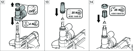
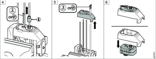
Remove the motor valve using an Allen key.
-
Pull up the motor housing and remove it.
Make sure that the motor does not fall out of the housing.
-
Loosen the gear wheel using an Allen key.
Only for a high-speed drill: Remove the spline connection.
-
Remove the cover with the split gear inside using an Allen key.
-
Gently push the split gear forward and remove it from the cover.
-
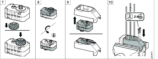
Change position of the bevel gear to the shaft on the opposite side of the split gear.
-
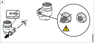
Turn the split gear in a suitable position.
The markings closest to the motor housing indicate the actual speed.
-
Put the split gear back into the cover.
-
Put the cover with the split gear back into original position and tighten the cover with screws using an Allen key.
-
Tighten the gear wheel with screw using an Allen key. If you cannot install the screw easily, turn the spindle to align the splines.
Only for a high-speed drill: Put the spline connection back into position.
-
Put the motor housing back into original position.
-
Put the motor valve back into original position and secure it with screws using an Allen key.


-
Push the start button.
-
Push the emergency stop button so that it locks in position. The air supply to the motor switches off and the spindle stops.
-
Disconnect the air hose.
-
Pull the emergency stop button to reset it.
-
Reconnect the air hose.
Changing the feed rate
By turning the feed cassette 180 degrees you can change the cassette feed rates. If you desire a different feed rate, select the appropriate cassette from the table feed rates in the section “Overview”.
Remove the old cassette.
Put the new cassette in position. Before you secure the cassette, read the marking on the cassette end closest to the spindle to make sure that the orientation of the cassette is correct.
Before operating the drill, do a functional test of the emergency stop button:
Push the start button.
Push the emergency stop button so that it locks in position. The air supply to the motor switches off and the spindle stops.
Disconnect the air hose.
Pull the emergency stop button to reset it.
Reconnect the air hose.
Operating Instructions
Before drilling operation

Following conditions apply prior to operating the drill:
Air hose connected to the drill
Front part locked in the fixture
Push the start button.
Push the emergency stop button so that it locks in position. The air supply to the motor switches off and the spindle stops.
Disconnect the air hose.
Pull the emergency stop button to reset it.
Reconnect the air hose.
Lock the tool in the jig.
Press the button (A or B) to release the indexer and adjust the position of the tool.
Release the button to lock in position.
Check that the lock pin on the indexer is level to the nut surface.
Rock the tool from side to side to confirm the tool being locked in position.


Releasing concentric collet without air pressure
-
Remove the screw.
-
Put the release tool in position and fasten it.
-
Turn the knob clockwise until the concentric collet releases.
-
Remove the drill from the fixture.
-
Remove the release tool and install the screw.


Unlocking and locking indexer
To unlock indexer, press and hold the button (A) or the Release button (B) and rotate the indexer shaft.

To lock indexer, rotate the indexer shaft until a "click" is felt and the safety button retracts.

Operating the drill
To start drilling... | push the start button. |
To stop drilling and retract the spindle into the start position... | push the retract button. |
To switch off the motor in case of emergency... | push the emergency stop button. |
To reset the emergency stop and restore normal operation... | disconnect the air hose. Pull the emergency stop button, reconnect the air hose to reset the air logic. |
Service
Maintenance Instructions
Service Recommendations
Preventive maintenance is recommended at regular intervals. See the detailed information on preventive maintenance. If the product is not working properly, take it out of service and inspect it.
If no detailed information about preventive maintenance is included, follow these general guidelines:
Clean appropriate parts accurately
Replace any defective or worn parts
Preventive Maintenance
Maintenance recommendations
Daily maintenance: test of emergency stop button.
Maintenance recommendations in the table below are for drilling holes in aluminum, titanium and CFRP.
For content of each kit, see spare parts list.
Maintenance intervals
One cycle is calculated on a standard stack of 10 mm.
Heavy Usage | Medium Usage | Light Usage | |||||
|---|---|---|---|---|---|---|---|
Cycles | Total drilling length (meter) | Action | Spare part | Use kit, | Use kit, | Use kit, | |
a Independent from the drilling thickness | |||||||
10,000 | 100 | Replace | Bevel gear | 4141 0410 91 | |||
20,000 | 200 | Replace | Chiplet | 4141 0713 9X | |||
Ratcheta | 4141 0713 9X | ||||||
25,000 | 250 | Replace | Ratcheta | 4141 0713 9X | 4141 0713 9X | ||
50,000 | 500 | Replace | Bevel gear | 4141 0410 91 | |||
Thrust bearing | 4141 0509 91 | ||||||
Chiplet | 4141 0713 9X | ||||||
Piston | 4081 0496 90 | 4081 0496 90 | 4081 0496 90 | ||||
Re-grease | Planetary shaft | Grease (Type A) | Grease (Type A) | N/A | |||
Overload clutcha | Grease (Type A) | Grease (Type A) | Grease (Type A) | ||||
100,000 | 1000 | Replace | Bevel gear | 4141 0410 91 | |||
Thrust bearing | 4141 0509 91 | 4141 0509 91 | |||||
Chiplet | 4141 0713 9X | ||||||
Planetary shaft | 4141 0444 90 | ||||||
Overload clutcha | 4141 0498 92 | 4141 0498 92 | 4141 0498 92 | ||||
200,000 | 2000 | Replace | Planetary shaft | 4141 0444 90 | |||
The drilling operation may produce different efforts (torque, thrust) than the estimated value due to different cutting tools geometry, material properties or lubrication. Therefore, the same operation can be categorized differently.
Heavy Usage | Medium Usage | Light Usage | |
|---|---|---|---|
Rotational speed and Drilling efforts | Speed 350-1200 rpm
| Speed 1600-3200 rpm | Speed 3200-7300 rpm |
Example of operations |
|
|
|
Lubrication Instructions
Rust protection and cleaning
Water in the compressed air can cause rust. To prevent rust we strongly recommend to install an air dryer.
Water and particles can cause sticking of vanes and valves. This can be prevented by installing an air filter close to the product to avoid pressure drop.
Lubrication guide
Valid lubricants:
|
Lubricant |
Description |
|---|---|
|
A |
Klübersynth PEG 46-121 (Ordering No. 4081 0487 90). |
|
B |
Rehnus LKR 03 (Ordering No. 4081 0487 91). |
O-rings should be greased before assembly with lubricant A or B (thin layer). Otherwise, it is specified in the table for each module.
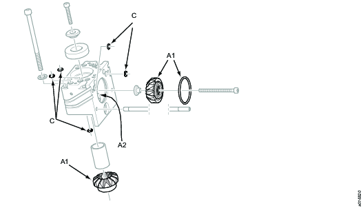
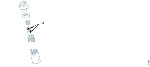
Motor valve
Total amount of lubricant: Approximately 2 ml.

Pos | Description |
|---|---|
A1 | Apply a thin layer of lubricant A or B. |
C | Do not apply lubricant. |
Motor housing
Total amount of lubricant: Approximately 12 ml.

Pos | Description |
|---|---|
A1 | Apply a thin layer of lubricant A or B. |
A2 | Apply 3 ml of lubricant A to cover cogs. |
A3 | Apply a thin layer of lubricant A. |
A4 | Fill lubricant A between needle bearings. |
B4 | Fill gap with 7 ml of lubricant B. |
C | Do not apply lubricant. |
Housing bevel gear
Total amount of lubrication: Approximately 9 ml.
Pos | Description |
|---|---|
A1 | Apply a thin layer of lubricant A or B. |
A2 | Fill gap with 6 ml of lubricant A. |
C | Do not apply lubricant. |
Housing, overview

|
Pos |
Description |
|---|---|
|
1 |
Housing bevel gear, for further information about lubrication please see housing bevel gear |
|
2 |
Housing upper, for further information about lubrication please see housing upper |
|
3 |
Housing lower, for further information about lubrication please see housing lower |
Spindle
Total amount of lubricant A: Approximately 0.5 ml.
Pos | Description |
|---|---|
A1 | Apply a thin layer of lubricant A. |
Split gear
Total amount of lubricant B: Approximately 10 ml.

Pos | Description |
|---|---|
A1 | Apply a thin layer of lubricant A or B. |
A4 | Fill lubricant A between needle bearings. |
B2 | Fill gap completely with lubricant B. |
Feed cassette
Total amount of lubricant A: Approximately 3 ml.

Pos | Description |
|---|---|
A2 | Ensure that all cog gaps are filled with lubricant A. |
C | Do not apply lubricant. |
Housing, lower
Total amount of lubricant: Approximately 5 ml.

Pos | Description |
|---|---|
A1 | Apply a thin layer of lubricant A or B. |
A2 | Fill gap with 3 ml of lubricant A. |
A3 | Apply a thin layer of lubricant A. |
A4 | Fill lubricant A between needle bearings. |
C | Do not apply lubricant. |
Housing, upper
Total amount of lubricant: Approximately 6 ml.

Pos | Description |
|---|---|
A1 | Apply a thin layer of lubricant A or B. |
A2 | Fill gap with 3 ml of lubricant A. |
A3 | Apply a thin layer of lubricant A. |
A4 | Fill lubricant A between needle bearings. |
C | Do not apply lubricant. |
Test after service
-
Push the start button.
Make sure that:
-
Motor is running.
-
Spindle is feeding forward.
-
No abnormal noises occur.
-
-
Push the emergency button.
Make sure that:
-
Air supply to the motor switches off immediately.
-
Emergency button stops in closed position.
-
-
Disconnect the air hose from the tool. Release the emergency button and connect the air hose to the tool. Push the start button to make sure that the tool starts.
-
Push the retract button.
Make sure that:
-
Spindle retracts in reverse direction (still rotating).
-
Motor turns off immediately (max 0.2 s) after the spindle reaches home position.
-
Spindle moves a short distance forward just before it stops rotating (can be difficult to see at low speed and small feeds).
-
-
Push the start button again and let the spindle move to drill finished position.
Make sure that:
-
Spindle starts retract in reverse direction immediately (still rotating).
-
Spindle returns to home position and the motor turns off.
-
-
Push the release button, hold it down, put the collet in a suitable bushing and release the release button.
Make sure that:
-
Collet is locked in bushing.
-
-
Push the start button, then push and hold down the release button.
Make sure that:
-
Tool is still locked in position.
-
-
Push the retract button, wait for the tool to stop in home position and push the release button and hold it down.
Make sure that:
-
Remove the collet from bushing.
-
Test after service is now finished.
Troubleshooting
Troubleshooting overview
The table below describes common problems, possible reasons and requiered actions.
Start any kind of troubleshooting by checking supply pressure. Reference value: 5-7 bar.
Problems | Possible reasons | Actions |
|---|---|---|
Tool starts immediately when air hose is connected. | Motor valve defective / stuck in open position.
| Replace the motor valve. |
Air logic unit defective. | Replace the air logic unit. | |
|
|
|
Motor runs, but spindle does not rotate. | Split gear, planetary gear, bevel gear or gear wheel in motor housing defective. | Preparation: Remove the motor valve and motor from the head. Spin the input shaft of the gear. |
|
| If the spindle rotates and the gears runs smooth: 1) Make sure the gear wheel in motor housing is OK. 2) Remove the motor from housing and make sure outgoing gear is OK. 3) Low speed unit: If the primary gear is OK, make sure the planetary gear is OK. 4) High speed unit: Make sure the splines adapter and gear / splines are OK. |
|
| If the spindle does not rotate and the gears hacks and sheaves: 1) Remove the split gear. 2) Rotate one axle and hold against the other.
If the split gears condition are OK: 3) Remove the bevel gears from bevel gear housing. 4) Make sure the bevel gears condition are OK. |
|
| If the bevel gears are OK, the gear wheels in the head are broken. |
|
|
|
Spindle rotates, but does not feed forward. | Air logic unit defective. | If clicking noise from the spindle: The spindle is probably stuck in home position, if not make sure feed gear is OK. Remove the spindle, see section Changing the spindle. Perform a test. Service is needed if the spindle stucks again. Test that spindle rotates. |
| Feed gear problem. | Make sure the declutching moment is correct, pls contact your Atlas Copco representative for instruction. |
| Air logic unit defective. | Replace the air logic unit. |
|
|
|
Spindle stops or feed back before drilling cycle is completed. | Drill bit defective. | Replace the drill bit. |
| Too low declutching moment in overload clutch. | Make sure the declutching moment is correct, pls contact your Atlas Copco representative for instruction. |
| Too high drill force. Too large drill size. | Verify rpm / feed / drill size according to specifications. |
|
|
|
Motor stops before end position. | Air leak in valve pin in upper housing. | Replace the valve pin. |
| O-ring missing or defective. | Make sure all o-rings in upper housing are OK. Replace if necessary. |
| Motor valve defective in upper housing. | Replace the motor valve. |
|
|
|
Spindle does not feed back when drilled finished. | Valve pin defective. | Replace the valve pin. |
| Valve pin blocked. | Verify that the valve pin are free and not blocked from grease and dirt. |
| Air logic unit defective. | Replace the air logic unit. |
| Rocker valve defective. | Replace the rocker valve. |
|
|
|
Spindle does not feed back when rettract-button is activated. | Air logic unit defective. | Replace the air logic unit. |
|
|
|
Tool does not start when start button is activated. | Too low supply pressure. | Make sure the supply pressure is correct, see section Technical data. |
| Emergency stop activated. | Pull the emergency stop button to reset it. |
| Air leak in valve pins in upper housing. | Make sure no air leaks exists. |
| Motor valve defective. | Replace the motor valve. |
| Air logic unit defective. | Replace the air logic unit. |
| Air leak in joints, caused of defective or missing o-rings. | Make sure the o-rings condition are OK. |
| Motor valve blocked. | Verify that the valve is free. |
| Rocker valve defective. | Replace the rocker valve. |
|
|
|
Tool starts slowly when start button is activated. | O-ring in motor valve are not lubricated. | For instruction, see section Lubrication. |
|
|
|
Motor starts, but stops immediately when start button is released. | Overload clutch stuck in open position. | Make sure the overload clutch functions properly. |
| Air leak in valve pins. | Replace the overload clutch. |
| Air logic unit defective. | Replace the air logic unit. |
|
|
|
Motor does not stop in home position or runs “unnecessary long time” before stoping. | Rocker valve defective.
| Replace the rocker valve. |
| Valve pin defective. | Replace the valve pin in upper housing. |
| Motor valve closing too slow. | Replace the motor valve. |
| Stop in valve pin. | Verify that valve pin in upper housing is free and not blocked. |
|
|
|
Incorrect spindle speed. Reference value: +/- 10% from rated speed. | Motor defective. | Replace the motor. |
| Split gear reversed. | Make sure the split gears spec. are correct and that right side is up. |
| Wrong split gear. | Verify that correct split gear is selected. |
|
|
|
Tool starts and feeds forward when start button is pushed down, but retract when start button is released. | Air leak in overload clutch valve pin. | Make sure that all o-rings are in good condition. Replace the overload clutch. |
|
|
|
Tool starts but retract when start button is released. | Air leak in overload clutch. | Replace the overload clutch. |
Recycling
Environmental Regulations
When a product has served its purpose it has to be recycled properly. Dismantle the product and recycle the components in accordance with local legislation.
Batteries shall be taken care of by your national battery recovery organization.
Recycling information for PFD1100RA (without inboard pump)

Pos | Part | Remark | Recycle as |
|---|---|---|---|
1 | Spindle guard | Remove transparent PC plastic before recycling | Metal, Aluminum |
2 | Air logic cover | Metal, Aluminum | |
3 | Motor | Metal, Aluminum | |
4 | Motor valve | Metal, Aluminum | |
5 | Counter | Electronic | |
6 | Spindle | Metal, Steel | |
7 | Head | Metal, Aluminum | |
8 | Split gear | Metal, Steel | |
9 | Cover | Metal, Aluminum | |
10 | Motor housing | Metal, Aluminum |