DISTRIBUTION BOX
Power supply
Product Information
General Information
Safety Signal Words
The safety signal words Danger, Warning, Caution, and Notice have the following meanings:
DANGER | DANGER indicates a hazardous situation which, if not avoided, will result in death or serious injury. |
WARNING | WARNING indicates a hazardous situation which, if not avoided, could result in death or serious injury. |
CAUTION | CAUTION, used with the safety alert symbol, indicates a hazardous situation which, if not avoided, could result in minor or moderate injury. |
NOTICE | NOTICE is used to address practices not related to personal injury. |
Warranty
Product warranty will expire in 12+1 months after dispatch from Atlas Copco's Distribution Center.
Normal wear and tear on parts is not included within the warranty.
Normal wear and tear is that which requires a part change or other adjustment/overhaul during standard tool maintenance typical for that period (expressed in time, operation hours or otherwise).
The product warranty relies on the correct use, maintenance, and repair of the tool and its component parts.
Damage to parts that occurs as a result of inadequate maintenance or performed by parties other than Atlas Copco or their Certified Service Partners during the warranty period is not covered by the warranty.
To avoid damage or destruction of tool parts, service the tool according to the recommended maintenance schedules and follow the correct instructions.
Warranty repairs are performed only in Atlas Copco workshops or by Certified Service Partners.
Atlas Copco offers extended warranty and state-of-the-art preventive maintenance through its ToolCover contracts. For further information, contact your local Service representative.
For electrical motors:
Warranty will apply, only when the electric motor has not been opened.
Website
Information concerning our Products, Accessories, Spare Parts and Published Matters can be found on the Atlas Copco website.
Please visit: www.atlascopco.com.
ServAid
ServAid is a portal that is continuously updated and contains Technical Information, such as:
Regulatory and Safety Information
Technical Data
Installation, Operation and Service Instructions
Spare Parts Lists
Accessories
Dimensional Drawings
Please visit: https://servaid.atlascopco.com.
For further Technical Information, please contact your local Atlas Copco representative.
Safety Data Sheets MSDS/SDS
The Safety Data Sheets describe the chemical products sold by Atlas Copco.
Please consult the Atlas Copco website for more information www.atlascopco.com/sds.
Country of Origin
For the Country of Origin, please refer to the information on the product label.
Dimensional Drawings
Dimensional Drawings can be found either in the Dimensional Drawings Archive, or on ServAid.
Please visit: http://webbox.atlascopco.com/webbox/dimdrw or https://servaid.atlascopco.com.
Overview
Applications
The DISTRIBUTION BOX is a power distribution unit for the following Atlas Copco controllers:
PowerMACS 4000
Power Focus 8 HV
Power Focus S HV
PF6 FlexSystem
Main Components and Functions
The DISTRIBUTION BOX has the following main components and functions:
One main switch.
One over-current protection.
Up to six units can be connected.
Fuses and Power Consumption
The DISTRIBUTION BOX contain two 10A automatic fuses with slow characteristics, one for each side of three connectors. Up to three controllerss are connected to each fuse.
The maximum input fuse is 63 A.
Use the table below to calculate the power and current consumption. As the average currents depends on the tightening cycles in a specific installation, the values below must be seen only as typical examples.
Motor size | Average Power(W) | Peak current (A)1 | Number of Spindles on each fuse | Number of spindles on one Main Switch Box 2 | Controller power loss (W) |
QST 34 | 100 | 1.1 | 3 | 60 | 45 |
QST 42 | 110 | 1,3 | 3 | 50 | 50 |
QST 50 | 120 | 2,0 | 3 | 36 | 55 |
QST 62 | 150 | 2,7 | 3 | 24 | 60 |
QST 80/90 | 200 | 3,4 | 3 | 18 | 70 |
1 Average of the max 2s during a tightening.
2 These numbers are based on a Main Switch Box connected to a 63 A input fuse with slow characteristics.
Technical Product Data
Technical Product Data can be found on either ServAid, or the Atlas Copco website.
Please visit: https://servaid.atlascopco.com or www.atlascopco.com.
Detailed Function Descriptions
DIN rails
The DISTRIBUTION BOX has some spare space on standard 35 mm DIN rails for customer specific additions, for example safety relay or power supply.
Principal Schematics
The Distribution Box is similar to a Main Switch Box, but it is not provided with a Main Switch. The principal schematics of the Distribution Box are as below:
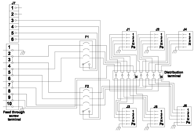
The Distribution Box contains six 3-phase outlets, divided into two groups, where one group consists of J1, J2 and J4, and the other group consists of J3, J5 and J6. Each group of outlets are fused with 10A miniature circuit breakers (F1 and F2).
Connectors in the User Area
The DISTRIBUTION BOX has a user area and a service area.
Installations in the user area of the DISTRIBUTION BOX must be performed by skilled personnel.
The user area is reached by opening the front of the DISTRIBUTION BOX. When opening the front, all the connectors for the cabling to Atlas Copco units and status indication is accessible. The cabling is led out through the bottom of the DISTRIBUTION BOX.
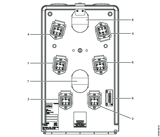
1 | J1 outlet, group 1 |
2 | J2 outlet, group 1 |
3 | J3 outlet, group 1 |
4 | J4 outlet, group 2 |
5 | J5 outlet, group 2 |
6 | J6 outlet, group 2 |
7 | Circuit breaker group 1 |
8 | Circuit breaker group 2 |
9 | X1: Connector for indication |
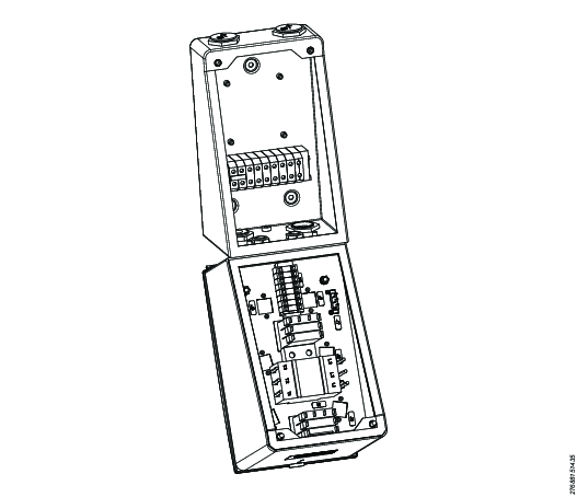
Connectors in the Service Area
The DISTRIBUTION BOX has a user area and a service area.
The power cable between the DISTRIBUTION BOX and a controller must not be connected or disconnected when the power is switched on.
The service area of the DISTRIBUTION BOX can be opened to be able to connect the cables. This must only be done by authorized personnel and is done by loosing a number of screws at the front of the box.
The incoming cable, as well as cables connecting the DISTRIBUTION BOX to other units, is connected to screw terminals. The cables are fed through strain relief cord connectors.
Connector for Status Indication
The connector for status indication (X1) is located in the user area. The connector is of the type Phoenix MC 1.5/6-ST-3.81.
Installations in the user area of the DISTRIBUTION BOX must be performed by skilled personnel.
Pin | Description |
|---|---|
1-2 | Not used. |
3-4 | Miniature circuit breaker position. The potential free contact is open when the circuit breaker (F2) is open/tripped. |
5-6 | Miniature circuit breaker position. The potential free contact is open when the circuit breaker (F1) is open/tripped. |
Outlets
The DISTRIBUTION BOX contains six 3-phase outlets; J1, J2, J3, J4, J5 and J6. The outlets are located in the user area.
Installations in the user area of the DISTRIBUTION BOX must be performed by skilled personnel.
Pin | Description |
|---|---|
1 | Phase L1. |
2 | Phase L2. |
3 | Phase L3. |
4 | Neutral. |
5 | Not used. |
6 | Ground. |
Power supply
The Atlas Copco high voltage controllers are designed to be used together with the Main Switch Box or Main Switch Box II and the Distribution box or Distribution Box II units. If the controllers are not connected to a Main Switch Box or aMain Switch Box II, with the option of also connecting a Distribution Box or aDistribution Box II, the following configuration must be used:
Install an external certified mains switch that disconnects all poles.
Install a certified mains fuse for all poles or other certified overcurrent protection device.
The incoming power must have the maximum fuse 10 A.
Main supply voltage: 3-phase 380–480 VAC ±10%, 50/60 Hz maximum 10 A.
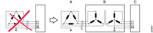
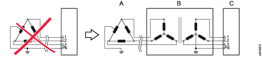
Generally, the Atlas Copco High Voltage controllers should only be connected to 3-phase, grounded industrial mains. A PHASE/GROUND voltage of 300 VAC must not be exceeded. In general, theses requirements are met in TN (Terra/Neutral) or TT (Terra/Terra) mains.
An isolation transformer with gounded star point o the secondary winding should be connected to ungrounded mains (IT (Isolated/Terra) mains) or asymmetrically grounded mains with PHASE/GROUND voltage exceeding 300 VAC.
Connection example:
TN or TT mains are to be preferred.

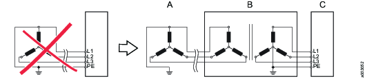
The examples below show some additional power supply system types using up to 480 VAC (phase to phase) where an isolation transformer is required.
Examples
Part | Description |
|---|---|
A | Factory power supply system |
B | Transformer |
C | Main Switch Box |
Example 1

Example 2
Example 3

Example 4
Example 5
Installation
Installation Instructions
Mounting
The DISTRIBUTION BOX can be mounted in any normal industrial environment without any extra enclosure, if local regulations do not prescribe otherwise.
When mounting the DISTRIBUTION BOX, consider the following:
Mount the DISTRIBUTION BOX in a convenient place where it is easily accessible.
It must be possible to open the DISTRIBUTION BOX when mounted.
Make sure the is enough space for the cables.
The ambient temperature must not exceed 50°C.
All units must be grounded using the potential equalization terminal. Connect an individual grounding wire (area minimum 2.5 mm2) from the units dedicated connection point to the equalization terminal. The grounding point should be the same as for the tool fixture. The purpose with the wires is to equalize potential deviations between different units in the system.
Installation Layouts
Standard cables come in lengths suitable for installations with rows of one DISTRIBUTION BOX plus one to six units in up to three rows. The number of units should be reduced in systems with large spindles that run high torque. Contact an Atlas Copco service technician for guidance.
Cabling
The incoming cable, as well as cables connecting the DISTRIBUTION BOX to other units, is connected to screw terminals inside the service area.
Cable requirements:
Maximum cable area for the connections is 10 mm2.
The gauge of the cable connecting the DISTRIBUTION BOX to another unit must be at least the same as the incoming cable gauge.
If the DISTRIBUTION BOX is connected to another unit, an external fuse is needed before the DISTRIBUTION BOX.
Grounding
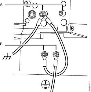
Each DISTRIBUTION BOX and controller must be grounded. On the US market, a 5.26 mm2 (10 AWG) ground wire must be used, and in all other markets a 6 mm2 must be used.
Grounding of the units:
Attach a ground wire from one of the threaded studs (A) at the bottom of the housing, to the mounting plate (B).
Attach a second grounding wire from the mounting plate (B), to the factory central grounding point.
The ground resistance between all system parts shall be < 0.1 Ohm. Depending upon the tool cable length and the number of spindles and how they are connected, there are two different alternatives how to meet this requirement. The QST tool cable ground resistance is <3 mOhm/m.
Alternative 1:
From the mounting plate to the spindle plate a 16 mm2 ground wire is used. In the US a 13.29 mm2 (6 AWG, equals 1.4 mOhm/m) wire is used. This will ensure proper grounding in all applications, independently of tool cable length and number of spindles.
Example 1:
One spindle with 60 m tool cable:
RTOOL CABLE < 3 mOhm x 60 m = 180 mOhm
RGND WIRE < 1.4 mOhm x 60 m = 84 mOhm
The resistance between mounting plate and spindle plate are these resistance in parallel:
RTOTAL = RTOOL CABLE // RGND WIRE = 180 m Ohm // 84 mOhm = 57 mOhm
This is < 100 mOhm, which is OK.
Alternative 2:
The extra ground wire between the mounting plate and the spindle plate can be omitted in certain applications:
If the tool cable is maximum 30m.
If two or more spindles are used, and grounded together at the spindle side, the tool cable ground resistance is connected in parallel. In that case the resistance will be reduced to a safe level. The resistance between the different spindle plates must be added to this value. If the spindles are connected to the same metal fixture this value may be neglected as it will be very low. If ground wires are used between the spindle plates to connect the spindles together, this resistance must be added. (A 6 mm2 wire = 3 mOhm/m).
This is illustrated in the following two examples:
Example 2:
One spindle with 30 m tool cable:
RTOOL CABLE < 3 mOhm x 30 m = 90 mOhm
This is < 100 mOhm. There is no need for the extra ground wire.
Example 3
Two spindles connected with 1 m of 6 mm2 ground wire between the two spindle plates and 60 m tool cable each:
RTOOL CABLE < 3 mOhm x 60 m / 2 = 90 m Ohm (Two tool cables in parallel).
RSPINDLE PLATES = 3 mOhm/m x 1 m = 3 mOhm
RTOTAL = 90 + 3 m Ohm = 93 mOhm
This is < 100 mOhm. There is no need for the extra ground wire.
Operation
Ergonomic Guidelines
Consider your workstation as you read through this list of general ergonomic guidelines to identify areas for improvement in posture, component placement, or work environment.
Take frequent breaks and change work positions frequently.
Adapt the workstation area to your needs and the work task.
Adjust for a convenient reach range by determining where parts and tools need to be located to avoid static load.
Use workstation equipment such as tables and chairs appropriate for the work task.
Avoid work positions above shoulder level or with static holding during assembly operations.
When working above shoulder level, reduce the load on the static muscles by lowering the weight of the tool, using for example torque arms, hose reels or weight balancers. You can also reduce the load on the static muscles by holding the tool close to the body.
Take frequent breaks.
Avoid extreme arm or wrist postures, particularly during operations requiring a degree of force.
Adjust for a convenient field of vision that requires minimal eye and head movements.
Use appropriate lighting for the work task.
Select the appropriate tool for the work task.
In noisy environments, use ear protection equipment.
Use high-quality inserted tools and consumables to minimize exposure to excessive levels of vibration.
Minimize exposure to reaction forces.
When cutting:
A cut-off wheel can get stuck if the cut-off wheel is bent or not guided properly. Use the correct flange for the cut-off wheel and avoid bending the cut-off wheel during operation.
When drilling:
The drill might stall when the drill bit breaks through. Use support handles if the stall torque is high. The safety standard ISO11148 part 3 recommends using a device to absorb a reaction torque above 10 Nm for pistol grip tools and 4 Nm for straight tools.
When using direct-driven screwdrivers or nutrunners:
Reaction forces depend on the tool settings and joint characteristics. Strength and posture determine the amount of reaction force that an operator can tolerate. Adapt the torque setting to the operator's strength and posture and use a torque arm or reaction bar if the torque is too high.
In dusty environments, use a dust extraction system or wear a mouth protection mask.
Service
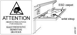
Preventing ESD Problems
The components inside the product and controller are sensitive to electrostatic discharge. To avoid future malfunction, make sure that service and maintenance is carried out in an ESD approved work environment. The figure below shows an example of an appropriate service work station.
Maintenance Instructions
Service Recommendations
Preventive maintenance is recommended at regular intervals. See the detailed information on preventive maintenance. If the product is not working properly, take it out of service and inspect it.
If no detailed information about preventive maintenance is included, follow these general guidelines:
Replace any defective or worn parts
Recycling
Environmental Regulations
When a product has served its purpose it has to be recycled properly. Dismantle the product and recycle the components in accordance with local legislation.
Batteries shall be taken care of by your national battery recovery organization.
Recycling Information
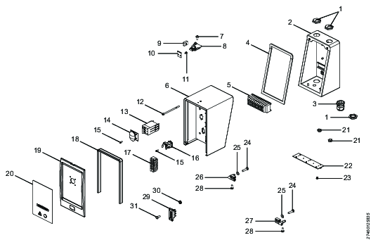
Position | Part | Recycle as |
|---|---|---|
1 | Blind plug | Steel |
2 | Wall mount | Steel |
3 | Strain relief | Polyamide |
4 | Gasket, Main box | Cellular rubber |
5 | Connecting terminal | Electronics |
6 | Main box | Steel |
7 | Screw | Steel |
8 | Rotary draw latch | Steel |
9 | Locking detail | Steel |
10 | Locking detail | Steel |
11 | Screw | Steel |
12 | Screw | Steel |
13 | Circuit breaker | Electronics |
14 | Splash cover | Electronics |
15 | Screw | Steel |
16 | Power connector, female | Electronics |
17 | Distribution terminal | Electronics |
18 | Front gasket | Cellular rubber |
19 | Cover front | Steel |
20 | Front panel | Electronics |
21 | Blind nut | Plastic, PA |
22 | Hinge | Steel |
23 | Screw | Steel |
24 | Screw | Steel |
25 | Washer | Steel |
26 | Hinge left | Steel |
27 | Hinge right | Steel |
28 | Screw | Steel |
29 | Signal connector | Electronics |
30 | Nut | Steel |
31 | Screw | Steel |