Introduction
In this section, you can find the basic information about the product and also the formatting conventions used in the topics.
General Data Protection Regulation (GDPR)
This product offers the possibility to process personal identifiable information such as system user name, role and IP-address. The purpose of this processing capability could be to enhance quality control through traceability and proper access management.
If you decide to process personal data you need to be aware of and comply with relevant personal data protection rules, including, in the EU the GDPR as well as other applicable laws, directives and regulations. Atlas Copco can in no way be held liable for any use made by you of the product.
Liabilities and Warnings
Liability
Many events in the operating environment may affect the tightening process and shall require a validation of results. In compliance with applicable standards and/or regulations, we hereby require you to check the installed torque and rotational direction after any event that can influence the tightening result. Examples of such events include but are not limited to:
initial installation of the tooling system
change of part batch, bolt, screw batch, tool, software, configuration or environment
change of air- or electrical connections
change in line ergonomics, process, quality procedures or practices
changing of operator
any other change that influences the result of the tightening process
The check should:
Ensure that the joint conditions have not changed due to events of influence.
Be done after initial installation, maintenance or repair of the equipment.
Occur at least once per shift or at another suitable frequency.
Warnings
About the User Guide
This user guide describes how to set up and configure an IxB tool using the IxB Software.
Revision History
Document Revision | IxB Software Version | Changes |
|---|---|---|
1.0 | 3.3 | First edition |
2.0 | 3.4 | Open end tuning function added: Open End Tuning Tightening program selection function added: General Settings Software update troubleshooting section added: Software Update Troubleshooting Maximum number of steps in a tightening program updated: Adding a Tightening Program Trace Settings function added: Step Parameters |
3.0 | 3.5 | Function for configuration of WLAN channels added: Configuring Channels Function for Statistical Process Control (SPC) added: SPC - Statistical Process Control Function for configuration of result presentation added: Configuring Result Presentation Settings Function for configuration of user permissions added: Configuring the PIN Settings Function for viewing server connection status added: Viewing Protocol Status Function for synchronizing traces added: Viewing Synchronized Traces Function for clearing results added: Performing Factory Reset and Clearing Results |
Target Group
This user guide is intended for anyone configuring or operating an IxB tool using the IxB Software.
Prerequisites
Anyone interested in learning more about the IxB Software can benefit from reading this user guide.
For a complete understanding of the technical aspects in the user guide the following is recommended:
Knowledge about tightening techniques
Experience of working with Power Focus 6000
For more information about Power Focus 6000, refer to the Power Focus 6000 User Guide.
Conventions
To enhance user understanding, certain formatting conventions are used throughout this document. The formatting conventions used are listed below.
Element | Notation | Description | Output |
|---|---|---|---|
General emphasis | In the Program workspace. | To make certain text elements stand out, or to highlight. | Text in Bold |
Graphical User Interface (GUI) items | Select the Function button. | Any reference to items found on screen in the GUI (for example, command buttons, icon names and field names). | Text in Bold |
Graphical User Interface (GUI) Path > | Generally, on the top of the GUI. | Navigation aid which keeps track of the location in the GUI. | For example: Controller > Program > Edit |
User input | Enter a Description for the program. | Any text input by the user. | Text in Bold |
File names | Enter a File Name for the export. | Files either exported from, or imported into the system. | Text in Bold Italic |
Variable and parameter names | Enter a Name for the export. | Variable and parameter names (not values). | Text in Italic |
Variable and parameter values | Enter a VALUE for the export. | Variable and parameter values. | Text in BOLD CAPS |
System output | Client.Domain.Models.ExportImportConfiguration | Any text output by the system. | Text in Monospace |
External links | Links to external sites that have information connected to the document or subject content. These could include:
| Selectable text to external sites | |
Internal documentation links |
If available, these links will be presented below the text. | Selectable text to internal content |
System Overview
A manufacturing system may consist of the functional blocks in the figure:
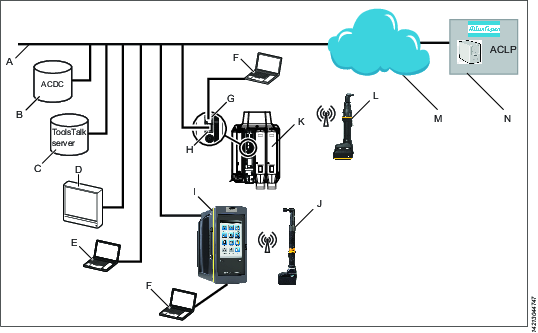
A | Factory network. | H | Controller factory port: connected to the factory network. |
B | ACDC: for storing tightening results and for statistical analysis. | I | Power Focus 6000 controller: used with handheld tools. |
C | ToolsTalk 2 server: for configuration and parameter settings for controllers and IxB tools. | J | Handheld battery tool: uses a wireless connection to the controller. |
D | Industrial PC (IPC): can be used as client terminal to the ToolsTalk 2 and ToolsNet servers. | K | PF6 Flex controller: used with fixtured tools. |
E | Portable computer connected to the factory network: can be used as client terminal to the ToolsTalk 2 and ToolsNet servers. | L | IxB handheld battery tool: uses a wireless connection to the factory network. |
F | Service computer: can be connected to the service port of a controller or an IxB tool. | M | The internet cloud. |
G | Controller service port: can be used to connect a service computer. | N | Atlas Copco Licensing Portal (ACLP): located at Atlas Copco and provides support to licensed functionality in the Functional Management System (FMS). |
The User Interface
Home Menu
The home menu contains the following items:
Menu Item | Description |
|---|---|
 | Tightening The Tightening menu shows a list of existing tightening programs stored in the tool. Selecting an individual program opens the different menus to configure and set parameters for the selected tightening program. |
 | Batch Sequence A batch sequence is one or more repetitive tightening programs in various combinations. Batch sequences are created and configured in the Batch sequence menu. |
 | Sources The Sources menu lists available options for controlling the selection of a tightening program, or a batch sequence, via digital input from different hardware. |
 | Configurations In this menu the following can be configured:
|
 | Integrated Controller Tool This menu includes items such as:
This menu also includes functions for software update and export/import of configuration parameters. |
 | Reports Displays the latest tightening results, events and NOK ratio. |
 | Settings This menu is used to set up specific settings such as:
|
 | License Assignment This menu gives an overview of the current license status and license sources. |
 | Help The Help menu contains the IxB Software user guide. |
Icons
The following table gives an overview of the icons and buttons available in the user interface:
Icon | Name | Description |
|---|---|---|
 | Back | Return to previous view. |
 | Home | Go to the Home screen. |
 | Go to Results | Go to the live results screen. |
 | Padlock | Opens a dialog box for PIN code. |
 | Events | Displays the latest tightening events. Define what events to display in the event configurations in the Settings menu. |
 | Validate | Validates tightening parameters against tool values. |
 | Add | Adds an item. |
 | Delete | Deletes an item. |
 | Protocol Status | Displays the Status Protocol pop-up window, which shows open protocol information and server connection status. |
 | Notice | Sign showing that a parameter is configured incorrectly. |
Installation and Upgrade
In this section, you can find information to help with the initial installation of the product, or upgrading from one version to another.
Installation Restrictions
Web Browser Requirements
The following web browsers are recommended for the IxB Software user interface:
Firefox
Google Chrome
Microsoft Edge
Licenses
Feature licenses are managed through the Functionality Management System (FMS). This allows customers to tailor tool functions to their specific needs through a dynamic licensing scheme.
Licenses can be obtained for individual features or collections of features and can be deployed across multiple virtual stations. The licenses can be returned to the pool when they are no longer required.
Licenses can be downloaded from the Atlas Copco License Portal (ACLP) and managed/distributed through ToolsTalk, or can be stored on a FMS Portable (USB drive) to be inserted into the tool.
Note that the creation and management of a customer account in the ACLP is not covered in this documentation. Contact the local Atlas Copco representative for more information.
There are three types of licenses:
Virtual Station Type
A fixed collection of features bundled together in a single package. The Virtual Station Type license determines, among other things, how many programs and sequences can be used, which tightening strategies are available, and the type of reporting that can be done. The features contained in each Virtual Station Type are features that often are used in conjunction with each other, or which have internal dependencies that require the presence of other features in the package. Virtual Station Types licenses are assigned in their entirety to a virtual station. The virtual station can then make use of all features contained in the Virtual Station Type. In order to be able to perform tightenings, a Virtual Station has to be assigned a Virtual Station Type license. Depending on the license type, various tightening options will be enabled or blocked.
Virtual Station Feature
Individual features can be purchased as a single licenses to complement the virtual station type licenses.
Controller Feature
In order to perform a tightening the Integrated Controller License must be stored on the tool.
License Sources
Licenses used on a tool can be pulled from several different sources. The number of simultaneous sources is limited to 10 (either 10 FMS Portable sources, or one License Server (TT2) in addition to nine FMS Portable sources). If a license is to be added from a source when the source limit (10) has been reached, all licenses from one source need to be removed from the tool to make room for licenses from the other source.
The Source Overview tab (License assignment > Source Overview) provides an overview of the licenses installed on the tool, as well as where they were installed from. A maximum number of 10 different sources can be displayed here, and each will be designated with FMS P (for FMS Portable, or dongle), or License Server (TT2).
Selecting any license source will present that source's detailed license source information. It lists the source name and type, as well as the number and type of licenses in each category (Virtual Station Type, Virtual Station Feature and Controller Feature).
Configuration of features governed by licenses can be done even in the absence of an installed license, for example, configuration of tightening programs. Assigning these features to a tool or virtual station is also possible. However, running the feature without a valid license will require the installation of the appropriate license.
License enforcement is performed at two stages: assignment and runtime (trigger pressed). If a feature for which no license is installed is assigned to a virtual station, a red exclamation mark will appear in the tool or task section of the user interface (depending on what is missing). If a feature, for which no license is installed, is started, an event will be presented informing which license is missing. It will not be possible to proceed without a correct license installed. Running an unlicensed feature will, in most cases, result in a locked tool.
Installing Licenses on the Tool
Note that license sources are limited to one (1) License Server (TT2) and nine FMS Portables (USB dongles) simultaneously. Licenses are either installed via the server (ToolsTalk2) or via FMS Portable. If the license source limit is reached, all licenses from one source need to be removed from the tool in order to add licenses from another source.
Existing licenses are checked against the license server every two hours. If no response from the license server is obtained within a period of 14 days, the affected licenses will be revoked. The user will also be warned when licenses are about to expire. When a license is within 7 days of expiration, the user will be presented with a warning once every two hours. If licenses are not renewed, they will expire and the affected functions will no longer be available.
Installing Licenses from the Server
Server based licenses are distributed through ToolsTalk2. For instructions on how to install server licenses, refer to ToolsTalk2 User Guide.
To enable license installation using ToolsTalk2, the correct license server settings must be configured in the tool.
Go to Settings in the home menu ans select Server connections in the left pane.
In the Atlas Copco License Manager field, set the switch to On.
Insert the correct Server port and Server host IP address (usually the same as the IP address for ToolsTalk2).
Select Apply.
Installing Licenses from FMS Portable (USB Dongle)
The Functionality Management System (FMS) uses a special FMS Portable device to transfer functionality to and from a tool. The USB flash drive contains both a general purpose memory area and a trusted storage area that is only accessible by the License Manager in a tool. The purchased feature items are downloaded from Atlas Copco to the general purpose area. The first time the FMS Portable is inserted into a tool with a License Manager, the file is detected and decoded and the feature items are transferred to the trusted storage area that is only accessible from a License Manager.
Connect the USB dongle to the tool via a USB adapter cable.

Prior to the license installation, make sure that the tool has a wireless connection set up to the factory network.
The USB License Management window will appear. The Pool column will show the total license count on the tool from all sources. The Available on FMS P column shows the licenses available on this dongle, while the From this FMS P column shows the number of licenses that have been moved to this tool from this particular FMS P.
Select the left-pointing arrow next to the license you want to install on the tool.
The number in the Available on FMS P column will decrease by 1 and the number in the From this FMS P column will increase by 1.
Removing Licenses from the Tool
Removing Licenses Installed on the Server
For instructions on removing server-installed licenses, refer to the ToolsTalk2 User Guide.
Removing FMS Portable-installed Licenses
Connect the USB dongle to the tool via a USB adapter cable.
Prior to the license removal, make sure that the tool has a wireless connection set up to the factory network.
If the USB License Manager window is not visible, go to License Assignment in the home menu.
Select the USB icon in the top right of the window. The USB License Manager dialog box appears.
Select the right-pointing arrow next to the license that is to be removed from the tool.
Licenses that are assigned to the virtual station can be removed from the tool. However, as a result the virtual station cannot be used.
Upgrading
Software Versions
Two software versions can be installed in the tool simultaneously. Installing a second version of the software is useful when performing upgrades on multiple tools. When production is ready for switching to the upgraded software, activation of the new software version is done from the IxB Software user interface, or with ToolsTalk 2.
Changing software versions does not transfer the tool configurations or tightening programs.
Software Activation
The tool can store two installed software versions. By using the Software activation, it is possible to choose which software version to use.
Make sure to keep the battery connected to the tool throughout the procedure.
Go to Integrated Controller Tool in the home menu and select Software in the left pane.
Select Current or Stored in the Software Activation window.
The tool is automatically restarted for the activation to take effect.
Update Software Version
Make sure to keep the battery connected to the tool throughout the procedure.
Go to the Integrated Controller Tool menu and select Software in the left pane.
Go to the Software Update field and select BROWSE.
Browse and choose the zip file with the applicable software and follow the instructions to finish installation.
Software Update Troubleshooting
An error during the software update will be indicated by the LED ring as follows:
Tightening direction LEDs are flashing eight times, followed by steady light for half a second. This flash pattern will be repeated until the tool automatically performs a restart. To view the error message, connect the tool to the IxB Software web user interface. As the IxB Software is loading, the error message will be displayed.
Possible error messages with corresponding resolve actions are listed below:
Error message | Resolve action |
|---|---|
Board hardware information not valid | Contact Market Support |
Device hardware information not valid | Contact Market Support |
File contents corrupt | Replace IAM (SD card) |
File incompatible with hardware | Replace IAM (SD card) |
File not found | Replace IAM (SD card) |
File read error | Replace IAM (SD card) |
Target communication timeout | Replace part defined as target |
Target reception error | Replace part defined as target |
Target unexpected reply | Replace part defined as target |
Target unreachable | Replace part defined as target |
Target transmission error | Replace part defined as target |
The target, that is the sub system where the error occurred, can be one of the following:
Target | Description |
|---|---|
BHMI | LED ring |
FTS | Front Transducer |
MCB | Motor Control Board |
MRT | Main board Real Time |
Rescue Mode
After three unsuccessful restarts the tool will enter Rescue Mode. In this mode it is possible to update the software and/or perform disk management.
Connect the tool to the USB port of the PC. Open a web browser and type in the address 169.254.1.1.
In the Rescue Mode user interface, go to the Software Update tab.
Select the file system to be updated and browse for the correct file.
Select the Update button.
Go to the Power tab and reboot the system.
Connect the tool to the USB port of the PC. Open a web browser and type in the address 169.254.1.1.
In the Rescue Mode user interface, go to the Disk Management tab.
Choose to repair file system or clean data, as appropriate.
Select the Submit button.
Go to the Power tab and reboot the system.
Configuration
In this section, you can find detailed information about how to create, modify, and verify product settings.
Configuration Options
The configuration and setting up of the tool can be done in the following ways:
IxB Software:The tool can be directly connected to a PC via a USB cable. If the tool is connected to a wireless network and its IP address is known, it can be accessed from a computer anywhere on the network.
ToolsTalk 2: If the tool is connected to a ToolsTalk 2 server, a ToolsTalk 2 client (PC) can access all connected tools and controllers through ToolsTalk 2. IxB tools, as well as Power Focus 6000 controllers and Flex controllers can be accessed.
ToolsTalk 2 in Station Setup mode: Provides a ToolsTalk 2 interface on a PC without a server installation. The PC is connected to the controller service port and provides access to one controller at a time.
Controller: This is applicable to Power Focus 6000 controllers which have a touchscreen. A controller can be configured regardless whether it is connected to the network or not.
This user guide covers the IxB Software. For information about ToolsTalk 2 and Power Focus 6000, refer to ToolsTalk 2 User Guide and Power Focus 6000 User Guide.
Getting Started
To create a better overview of the system, this section provides a quick guide covering the basic steps required to get started with the Tensor IxB tool and IxB Software. The section does not explain every feature of the system, but instead focuses on the most basic ones.
Connect the tool to a PC and access the user interface. Set up a wireless connection between the tool and the network.
Define a tightening program containing all relevant parameters of a tightening, for example target angle and target torque.
If applicable, create a batch sequence. One or several tightening programs can be added to a batch sequence which works as a series of tightening programs. A batch sequence can for example be a certain number of tightenings with a tightening program, or a sequence of different tightening programs.
Assign a task to the virtual station of the tool. The task can be either a tightening program, a batch sequence, or a specified digital input (from for example a barcode scanner).
Accessing the IxB Software User Interface
Remove the cover of the tool's USB connection port.
Connect the tool to the USB-port of the PC.
Open a web browser and type in the address of the IxB Software user interface: 169.254.1.1.
To access the user interface wirelessly, refer to the instructions in the section Configure a Wireless Client.
Creating a Tightening Program
Go to Tightening in the home menu.
Select the plus icon.
In the Choose Operation Mode window, select Tightening.
Open the Properties window and type in a valid Maximum Torque Limit for the specific tool. Type Enter. Close the Properties window.
Open the Steps pane on the right and drag and drop the steps to create a tightening program.
Set Monitors and Restrictions for each step as applicable and press the Enter key.
The tightening program must have a loosening program configured.
Go to Tightening in the home menu.
Select the plus icon.
In the Choose Operation Mode window, select Loosening.
Open the Properties window and type in a valid Maximum Torque Limit for the specific tool. Type Enter. Close the Properties window.
Open the Steps pane on the right and drag and drop the steps to create a loosening program.
Set Monitors and Restrictions for each step as applicable and type Enter.
Go to Tightening in the home menu and select a tightening program from the list.
Expand Properties by selecting the arrow.
Under General settings, select Loosening Program and choose a loosening program in the list. Type Enter.
Assigning a Task to the Virtual Station
Go to Integrated Controller Tool in the home menu.
Under Virtual Station > Task select Choose task.
Choose a Tightening program from the list.
Working with the Tightening Tab
This section describes the multistep tightening strategy and how to create a tightening program.
Some features require licenses distributed through the Functionality Management System (FMS). Whereas configuration of features is possible without specific licenses, the assignment and use of those features will require the correct license to be installed on the tool.
Multistep Tightening Strategy
A multistep tightening is a tightening done in several steps. The number of steps and the type of the steps vary depending on the tightening to be done. A multistep tightening program is highly configurable, including monitoring functions and restrictions. A total of 16 steps can be added to a multistep program.
Restrictions are used to make sure the tightening stops if something unexpected occurs. These restrictions could, for example, test that a maximum set torque is not reached or that a part of the multistep tightening does not take too long to run. Every step can have up to four restrictions each. Each step has mandatory step restrictions and optional step restrictions. The mandatory restrictions are included when dragging a new step to the multistep program.
Monitors are used to verify that the tightening was made according to the specification. This can be, for example, angle limits or torque limits. Every step can have up to eight monitors each. Each step has mandatory step monitors and optional step monitors. The mandatory monitors are included when dragging a new step to the multistep program.
Multistep Configuration User Interface
The user interface for configuring a multistep program can be divided into three main areas:
In the top there is a drop-down menu containing the Properties of the multistep tightening program. Here general properties such as program name, overall program monitor and validation can be set.
To the right there are three tabs containing the Steps, Monitors and Restrictions that can be used to build the multistep program. To use any of the items, select the appropriate tab, and drag the item in the list to the tightening area. Depending on its function, either drop the item between the beginning and the end of the program (for steps), or on top of a particular step (for monitors and restrictions).
The main area of the user interface is made up of the tightening area. This is the area that includes all the steps in the tightening program.
Step Parameters
The following step parameters are common for many of the step types. The parameters are set in the step properties window which is displayed when selecting a step in the tightening program.
Parameter | Description |
|---|---|
Name | Name of the step. |
Rotational direction | Each of the tightening steps can run either forward, that is to make a tightening, or reverse, to loosen the screw slightly. The arrows indicate this direction. Many of the tightening steps have a direction hard-coded to forward, for example Tighten to Angle, or Tighten to Torque. Steps such as Loosen to Angle or Loosen to Torque have their direction automatically set to reverse. The reverse setting is not allowed for tools configured with Gear Front Attachment (GFA) of type open end. The tightening direction of the tightening program must be the same as the tightening direction of the open end tool for a tightening to be allowed to be run. It is possible to assign a loosening program to a tightening program for an open end tool, but if the direction switch is set to run the loosening program, the tool will be locked. |
Step category | For each step, there is an option to choose a step category. By selecting step category, the NOK tightenings will be listed in the event result view with related detailed status together with the corresponding multistep error information. If no selection is made, the detailed status will be set to "uncategorized multistep error". The related detailed status can be customized. |
Angle window | A joint is considered Hard if the screw is tightened to its full torque and it rotates 30 degrees (or less) after it has been tightened to its snug point. A Soft joint rotates 720 degrees or more after it has been tightened to its snug point. The hardness parameter defines the Angle Window for the gradient calculation. The harder the joint - the smaller the angle window. |
Speed Ramp / Acceleration (only available in ToolsTalk 2) | For most of the steps it is possible to specify how the acceleration to the target speed should be achieved. Three different settings are possible; Hard, Soft and Manual. The acceleration defined will be used whenever a step is started. Regardless whether the tool is already running with speed at the beginning of the step, the ramp will be used to accelerate to the target speed of the step. This will be the case even if the speed at the start of the step is higher, or lower than the target speed. |
Speed ramp - Hard and Soft mode |
|
Speed ramp - Manual mode |
|
Using speed shifts | 1−5 angle triggers or torque triggers can be defined during a step, where the speed will shift. Within one step, all the speed shift triggers are based on the same property, that is either torque or angle. They cannot be mixed within one step. The Torque triggers and Angle triggers must be less than the step target, depending on the type of the step and the trigger type. The Torque trigger and Torque speed also validate against the Max torque and Max speed of the tool. A warning or error indicator occurs whenever the Speed Shift settings exceed either the tool max values, or step max values. The Torque triggers and Angle triggers must be less than the step target, depending on the type of the step and the trigger type. The Torque trigger and Torque speed also validate against the Max torque and Max speed of the tool. A warning or error indicator occurs whenever the Speed Shift settings exceed either the tool max values, or step max values. It is possible to push the settings to the tool when a tightening program has a warning, but not when a tightening program has an error (fault) indicator. |
Brake type | The braking behavior of a multistep tightening program can be controlled at two possible locations in the program: in a step preceding a reversal of direction of the tightening, and/or at the final step of the tightening program. At other locations in the tightening program, the braking parameters will not be available in the step's general settings. Braking can be set to either Ergo stop or Inertia. Inertia will brake the tool completely, while Ergo stop will allow for a more ergonomic slowing down of the tightening. Inertia has no additional parameters. Ergo stop parameters:
|
Trace Setting
When the trace configuration is enabled on the program level, the trace resolution can be configured on step level. The setting for Trace Setting defines how the sampling should be done on each specific step.
Parameter | Description |
|---|---|
Trace Setting |
|
Sample Time | Choose the sample time from the drop-down list (0.25 - 1000 ms) |
Sample Angle | Choose the sample angle from the drop-down list (0.25 - 20 degree) |
With this trace recording the sample rates will not be the same in all the steps, instead the sample rate depends on the configuration in each step. This means the trace is divided into one trace for each step.
The maximum number of samples in a trace is 4096.
If a tightening produce more than 4096 values a down-sampling will take place. This is done by removing every second trace sample from the whole tightening and when continue the recording with half the resolution. This process will be repeated every time the 4096 sample limit is reached.
If more than 2048 in total was recorded, this process will result in a trace between 2048 and 4096 samples.
If the limit if 4096 samples is reached the configured trace sample times will no longer be followed. Instead the sample times will be doubled or quadrupled etc., depending on how many times the down sampling has taken place. Since all steps are down sampled the relation between the steps will still be the same though. If a step was configured with double sample time compared to another step, this will still be the case in the final trace regardless how many times a down-sampling has occurred.
If more than 4096 samples is recorded, the configured trace sample times will no longer be followed. Instead the sample times will be doubled or quadrupled, etc., depending on how many times the down sampling has taken place. Since all steps are down sampled the relation between the steps will still be the same though. If a step was configured with double sample time compared to another step, this will still be the case in the final trace regardless how many times a down-sampling has occurred.
Trace channel | Note |
|---|---|
Torque | Available for all tools equipped with a torque transducer |
Angle | Available for all tools |
Torque Second | Only available for tools with two torque transducers |
Angle Second | Only available for tools with two angle transducers |
Current | Available for all tools |
Gradient | Available if some step/restriction/monitor produces the gradient values |
Overview of Available Steps
The steps described in this section are available for creation of multistep tightening programs.
The following tightening steps are not supported for tools configured with Gear Front Attachment (GFA) of type open end:
Loosen to Angle
Loosen to Trigger Release
Loosen to Torque
Engage
Socket Release
Tighten to DynaTork
W – Wait
In this step the tool waits the specified amount of time. The tool does not rotate while waiting.
The tool waits the specified time. If the hold position is set to On the tool holds the position during the Wait time.
SR - Socket Release
This step runs the tool with speed n in the backward direction until the target angle is reached. The target angle is measured from the start of the step.
This step is only allowed to use as the last step in the tightening path of a multistep tightening program. However, it is possible to add a sync point after this step.
Parameter | Description |
|---|---|
Target angle | The angle target. Default: 3º , must be > 0 |
Speed ramp type | Hard, soft, or manual. Default: Hard. If you select Manual, the Speed ramp field opens. |
Speed ramp | If Speed ramp type is Manual, this field opens. Default: 500 rpm/s. |
Speed | Default: 60 rpm. |
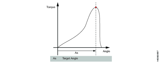
A – Tighten to Angle / Loosen to Angle
A – Tighten to Angle
This step runs the tool until the target angle is reached. The target angle is measured from the start of the step.
A – Loosen to Angle
This step runs the tool with the speed n in the backward direction until the angle target is reached. The target angle is measured from the start of the step.
Parameters
Parameter | Description |
|---|---|
Target angle | The angle target. Must be > 0. |
Speed | Default: 60 rpm. |
Speed ramp type | Hard, soft, or manual. Default: Hard. If you select Manual, the Speed ramp field opens. |
Speed ramp | If Speed ramp type is Manual, this field opens. Default: 500 rpm/s. |
Brake (Only valid for PF6 Flex and PF6 Stepsync controllers). | If On the tool will be stopped when the target is reached. If Off the program goes directly to the next step without stopping the tool. |
TrR – Loosen to Trigger Release
This step runs in the backward direction until the tool trigger is released (loosen). It can only be used as a last step in a program.
Parameter | Description |
|---|---|
Speed | Numerical value for rotation speed; in rpm. |
Speed Ramp Type | List of options where speed ramp can be chosen [Hard, Soft, Manual] |
TTTR – Tighten to Trigger Release
This step runs until the tool trigger is released (tighten). It can only be used as a last step in a tightening program.
Parameter | Description |
|---|---|
Speed | Numerical value for rotation speed; in rpm. |
Speed Ramp Type | List of options where speed ramp can be chosen [Hard, Soft, Manual] |
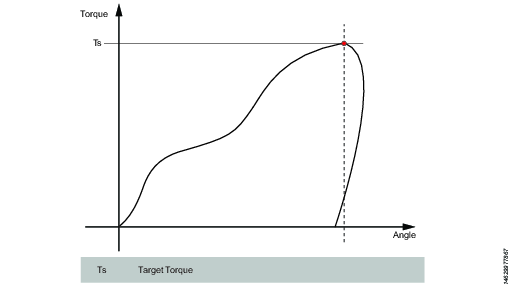
T - Tighten to Torque / Loosen to Torque
T – Tighten to Torque
This step runs the tool with the programmed speed in forward direction until the target torque is reached.
Parameter | Description |
|---|---|
Target torque | The torque target. Must be > 0. |
Speed ramp type | Hard, soft, or manual. Default: Hard. If you select Manual, the Speed ramp field opens. |
Speed | Default: 60 rpm. Must be > 0. |
Speed ramp | If Speed ramp type is Manual, this field opens. Default: 500 rpm/s. |
Brake (Only valid for PF6 Flex and PF6 Stepsync controllers). | If On the tool will be stopped when the target is reached. If Off the program goes directly to the next step without stopping the tool. |
T – Loosen to Torque
This step runs the tool with the speed in the backward direction. For the step to be active, the torque must first exceed 110 % of the Target torque. The Target torque should be set to a positive value. After reaching the target torque, the step runs until the torque drops below the target torque.
Parameter | Description |
|---|---|
Target torque | The torque target. Must be > 0. |
Speed ramp type | Hard, soft, or manual. Default: Hard. If you select Manual, the Speed ramp field opens. |
Speed | Default: 60 rpm. Must be > 0. |
Speed ramp | If Speed ramp type is Manual, this field opens. Default: 500 rpm/s. |
Brake (Only valid for PF6 Flex and PF6 Stepsync controllers). | If On the tool will be stopped when the target is reached. If Off the program goes directly to the next step without stopping the tool. |
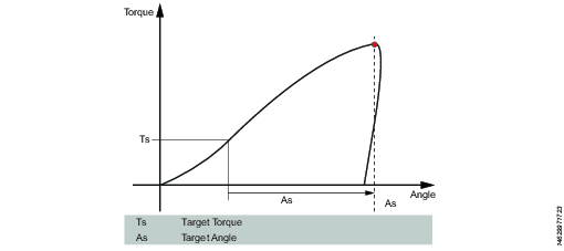
T+A – Tighten to Torque Plus Angle
This step runs the tool until the target torque is reached. From this point it continues to run an additional target angle.
Parameter | Description |
|---|---|
Target torque | The torque target. Must be > 0. |
Target angle | The angle target. Must be > 0. |
Speed ramp type | Hard, soft, or manual. Default: Hard. If you select Manual, the Speed ramp field opens. |
Speed ramp | If Speed ramp type is Manual, this field opens. Default: 500 rpm/s. |
Speed | Default: 60 rpm. |
Brake (Only valid for PF6 Flex and PF6 Stepsync controllers). | If On the tool will be stopped when the target is reached. If Off the program goes directly to the next step without stopping the tool. |
T|A – Tighten to Torque or Angle
This step runs the tool with the speed n in the forward direction until the first of either torque target or angle target is reached. The torque and angle measurements start at the beginning of the step.
Parameter | Description |
|---|---|
Target torque | Must be > 0. |
Target angle | Must be > 0. |
Speed | Default: 60 rpm. Must be > 0. |
Speed ramp type | Hard, soft, or manual. Default: Hard. If you select Manual, the Speed ramp field opens. |
Speed ramp | If Speed ramp type is Manual, this field opens. Default: 500 rpm/s. |
Brake (Only valid for PF6 Flex and PF6 Stepsync controllers). | If On the tool will be stopped when the target is reached. If Off the program goes directly to the next step without stopping the tool. |
T&A – Tighten to Torque and Angle
The tool runs until with the specified speed in the forward direction until both target torque and target angle are reached. The target torque and the target angle must be set to > 0.
Parameter | Description |
|---|---|
Target torque | Must be > 0. |
Target angle | Default: 0. Must be > 0. |
Speed | Default: 60 rpm. Must be > 0. |
Speed ramp type | Hard, soft, or manual. Default: Hard. If you select Manual, the Speed ramp field opens. |
Brake (Only valid for PF6 Flex and PF6 Stepsync controllers). | If On the tool will be stopped when the target is reached. If Off the program goes directly to the next step without stopping the tool. |
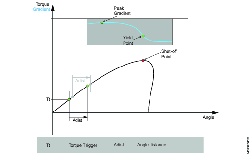
Y – Tighten to Yield
This strategy runs the tool with the speed in the forward direction until the yield point is detected. The yield point is found by monitoring the torque gradient from the point where the torque goes above the Trigger Torque level, calculated based on Torque and Angle distance measurements. The Angle distance parameter is set according to the specified hardness of the joint.
Set the Gradient angle window (for hard joint, for soft joint or for manually setting of the Angle window). If Manual is selected, the Angle Window must be set. A joint is considered Hard if the screw is tightened to its full torque and it rotates 30 degrees or less after it has been tightened to its snug point. A Soft joint rotates 720 degrees or more after it has been tightened to its snug point. The hardness parameter defines the Angle Window for the gradient calculation. The harder the joint - the smaller the angle window.
Parameter | Description |
|---|---|
Gradient Angle Window | Specifies Angle Window:
|
Angle Window | Available when Gradient Angle Window is set to Manual. Must be > 0 and <= 100. |
Trigger Torque | The angle measurement starts at this trigger. Must be >= 0 and < Tool MaxTorque. |
Damping | Frequency in which the gradient is being calculated. Must be > 0 and < 100 and < Angle window. |
Yield Point Percentage | Must be >= 20 % |
Speed | Default: 60 rpm. Must be > 0. |
Speed ramp type | Hard, soft, or manual. Default: Hard. If you select Manual, the Speed ramp field opens. |
Torque Filter Type | The type of the filter:
|
Cut-off Frequency | Needs to be specified when Torque Filter Type is set to Low pass:
|
Number of Samples | Needs to be specified when Torque Filter Type is set to Sliding Average:
|
Brake (Only valid for PF6 Flex and PF6 Stepsync controllers). | If On the tool will be stopped when the target is reached. If Off the program goes directly to the next step without stopping the tool. |
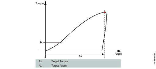
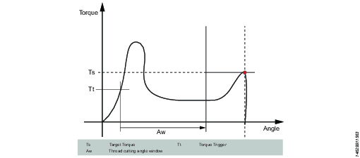
ThCT – Thread Cutting to Torque
The Thread Cutting to Torque function enables tightening where the Rundown torque required is greater than the Rundown complete torque, for example when tightening thin layers of metal using self-threading (or selftapping) screws. The tool runs in forward direction until the Thread Cutting Angle (Aw) is reached. The thread cutting angle window is measured from when the torque passes Thread Cut Trigger Torque (Ttc) for the first time. From the point where Thread cutting angle is reached, the step continues to run until the Target Torque (Tt) is reached.
Parameter | Description |
|---|---|
Target torque | Must be > 0. |
Thread Cutting Angle Window | Default: 0. Must be > 0. |
Trigger Torque | The angle measurement starts at this trigger. |
Speed | Default: 60 rpm. Must be > 0. |
Speed ramp type | Hard, soft, or manual. Default: Hard. If you select Manual, the Speed ramp field opens. |
Brake (Only valid for PF6 Flex and PF6 Stepsync controllers). | If On the tool will be stopped when the target is reached. If Off the program goes directly to the next step without stopping the tool. |
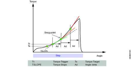
RD – Rundown
Rundown step is the part of the tightening from when the screw enters the thread until just before the screw head touches the underlying surface and snug point is reached. The torque required during rundown does not contribute to any clamping force.
This step runs the tool with the speed in the forward direction, and depending on the Rundown Type, Torque or Snug the step behavior is as follows:
Rundown Type: To Torque: The step stops when the specified target torque is found.
Rundown Type: To Snug: The snug gradient calculation starts at the specified torque trigger level Tt. If no torque trigger is set the gradient calculation is started at the start of the step.
The slope calculation is made between two angle points Ad degrees apart and is calculated as: (Tn – Tn-1) / (An – An-1) and as soon as two slopes after each other are larger than TSLOPE the snug point is found.
Parameter | Description |
|---|---|
Rundown type | To Torque or To Snug. |
Target torque | Default: "not set". Must be > 0. |
Speed | Default: 60 rpm. Must be > 0. |
Speed ramp type | Hard, soft, or manual. Default: Hard. If you select Manual, the Speed ramp field opens. |
Speed ramp | If Speed ramp type is Manual, this field opens. Default: 500 rpm/s. |
Trigger Torque | If Rundown type is To Snug, the Trigger torque field is displayed. Default: "not set". Must be > 0. |
Delta Angle | If Rundown type is To Snug, the Delta angle field is displayed. Default: "0". Must be > 0. |
Torque Rate | If Rundown type is To Snug, the Torque rate field is displayed. Default: "0". Must be > 0. |
Brake (Only valid for PF6 Flex and PF6 Stepsync controllers). | If On the tool will be stopped when the target is reached. If Off the program goes directly to the next step without stopping the tool. |
Engage (E)
This step runs the tool in both directions until the socket engages the screw. The step continues until Target torque or Target angle is reached, provided that Continue if not Engaged is set to Yes. If Target Angle is reached in any direction, the direction is reversed. Limit the search iterations by entering Max Engage Attempts. If Target Torque is reached in any direction the step will finish with OK status.
Ext - External Result
External result is a strategy used when an OK tightening is indicated by an external digital signal (and not by torque or angle values measured during tightening). This external signal can be provided through any means that can provide a digital signal to the tool.
When the signal is sent, the result view (logged data) will show the value of the Target parameter provided in the tightening program (specified torque value, angle value, or text string). These (torque and angle) values do not represent actual measured values, but only inserted text.
Parameter | Description |
|---|---|
Torque <Target torque> | Numerical value for desired displayed target torque value. A signal could for example come from a Click Wrench and display <Target torque>. |
Angle <Target angle> | Numerical value for desired displayed target angle value. A signal could for example come from a Click Wrench and display <Target angle>. |
Text | Alphanumerical string for desired displayed text. For example: "Oil has been changed". |
The following steps are not supported:
Step Label | Name |
|---|---|
DI | Run until Digital Input - N/A |
DT | Tighten to DynaTork - N/A |
MWR | Mechatronic Wrench - N/A |
WP | Wrench Production - N/A |
WQ | Wrench Quality - N/A |
C | Clutch - N/A |
CL | Clutch Loosening - N/A |
TM | Manual Tighten to Torque - N/A |
Overview of Available Step Monitors
Step monitors are used to verify that the tightening was achieved according to the specification, for example, angle limits or torque. Each step has mandatory step monitors and optional step monitors. The mandatory monitors are included when dragging a new step to the multistep program. The optional monitors are flexible and can be added as needed in the multistep program. Each step can have up to eight monitors.
The Angle and Peak Torque monitors are automatically added by default to every step in a multistep tightening program.
A – Angle
This step monitor measures the maximum angle reached during the monitor and checks that it is between High limit and Low limit. The angle measurement starts at the start of the monitor or, if specified, at the point where the torque passes Trigger torque for the first time during the monitor.
Parameter | Description |
|---|---|
Type | Four angle types are available: Peak angle (default), Angle at peak torque, Shut off angle, and Angle at end. |
Trigger torque | The angle measurement starts at this trigger. |
Low Limit | Lowest acceptable angle. |
High Limit | Highest acceptable angle. |
YA – Angle from Yield
This monitor measures the peak angle reached from the yield point and checks that the peak angle is within the limit.
Parameter | Description |
|---|---|
Gradient Angle Window | Specifies Angle Window:
|
Angle Window | Available when Gradient Angle Window is set to Manual. Must be > 0 and <= 100. |
Yield Point Percentage | Must be >= 20 % |
Trigger Torque | The angle measurement starts at this trigger. Must be > 0 and < Tool MaxTorque. |
Damping | Frequency in which the gradient is being calculated. Must be > 0 and < 100 and < Angle window. |
Low Limit | Lowest acceptable angle. Must be >= 0 |
High Limit | Highest acceptable angle. Must be > 0 |
Torque Filter Type | The type of the filter:
|
Cut-off Frequency | Needs to be specified when Torque Filter Type is set to Low pass:
|
Number of Samples | Needs to be specified when Torque Filter Type is set to Sliding Average:
|
MT – Mean Torque
This monitor measures the average torque during the monitor and checks the calculated value is within the limits.
Parameter | Description |
|---|---|
Type | Specifies start condition:
|
Torque Trigger | Available when Type is set to Trigger Torque, Angle Trigger or Angle Window. Must be >= 0 and < Tool Max Torque. |
Angle Trigger | Available when Type is set to Angle Trigger or Angle Window. Must be > 0. |
Angle Window | Available when Type is set to Angle Window. Must be > 0.
|
Time Interval | Available when Type is set to Time Interval. Must be > 0. |
Low Limit | Lowest acceptable torque. |
High Limit | Highest acceptable torque. |
PT – Peak Torque
This step monitor measures the maximum torque reached during the monitor, including any over shoot, and checks that it is between High limit and Low limit.
Parameter | Description |
|---|---|
Low Limit | Lowest acceptable torque. |
High Limit | Highest acceptable torque. |
PTCA – Post Thread Cut Angle
Measures the angle achieved during the monitoring and checks that it is between the specified angle limits. The Trigger Torque level is ignored until the end of the Thread cut angle window is reached. After that, the angle measuring starts as soon as the measured torque is above Trigger Torque. The parameter Stop Condition specifies where the angle measurement should end.
Parameter | Description |
|---|---|
Trigger torque | Must be >= 0 |
Thread cutting angle window | Must be > 0 |
Angle measurement type | Peak angle Angle at peak torque Shut off angle Angle at end |
Thread cut trigger torque | Must be >= 0 |
Low Limit | Must be >= 0 |
High Limit | Must be > 0 Must be > Low limit |
PTCPT – Post Thread Cut Peak Torque
Measures the maximum torque achieved during the monitoring, including any over-shoot, and checks that it is between the Torque limits. All torque values are ignored until the end of the Thread cut angle window has been reached.
Parameter | Description |
|---|---|
Thread cut trigger torque | Must be >= 0 |
Thread cutting angle window | Must be > 0 |
Low Limit | Must be >= 0 |
High Limit | Must be > 0 Must be > Low limit |
PVTH – Post View Torque High
This monitor checks that all torque values in the angle window are below the limit.
All torque values in the Angle Window Length should be below the High limit. The Angle Window starts at the angle degrees set in Start Angle in reverse direction from the shut-off point. This then spans for the angle degrees set in Angle Window Length in reverse direction. If Start Angle is left blank the Angle Window starts at the shut-off point. The torque values used in the monitor are based on the mean torque value, calculated over Number of Samples. If the total angle of the step is less than Start Angle plus Angle Window Length the monitor will report NOK.
Parameter | Description |
|---|---|
Start Angle | Must be >= 0 |
Window length | Must be <= 0 |
Number of samples | 1 |
High Limit | Highest acceptable torque. |
PVTL – Post View Torque Low
Same as monitor Post View Torque High but this monitor checks that all torque values in the Angle Window Length are above Low Limit instead.
Parameter | Description |
|---|---|
Start Angle | Must be >= 0 |
Window length | Must be <= 0 |
Number of samples | 1 |
Low Limit | Lowest acceptable torque. |
PrT – Prevailing Torque
The monitor calculates the prevailing torque value in the Window Length and checks that it is between the Torque limits. The Angle Window starts at the angle degrees set in Start Angle in reverse direction from the shut-off point. This then spans for the angle degrees set in Angle Window Length in reverse direction. If Start Angle is left blank the angle window starts at the shut-off point. The calculated prevailing torque value is the mean or peak torque value (depending on the parameter set by the user) during the Window Length. The calculated value is saved as result data Prevailing Torque Measured. If Torque compensation is set to On, the Prevailing Torque Measured will be subtracted from all torque result values in consecutive steps. Any previously calculated prevailing torque compensation values will no longer be subtracted from torque result values. If Torque compensation is set to No, no subtraction will be made in consecutive steps.
If the total angle of the step is less than the Start Angle plus Window Length, then the monitor will report NOK.
Prevailing torque can be measured as an average of measured values, or at peak torque. To choose between these two modes, set the Use Value parameter to either Mean torque (for average values), or Peak torque (for peak value).
Parameter | Description |
|---|---|
Torque Compensation | On or off. |
Start Angle | Must be > 0 |
Window length | Must be >= 0 |
Low Limit | Must be > 0 |
High Limit | Must be >= 0 |
Use value | Mean torque (for average values), or Peak torque (for peak value). |
SOT – Shut Off Torque
The shut off point is the point where the step reaches its target. The torque is measured at the shut off point and checked to be between High limit and Low limit.
Parameter | Description |
|---|---|
Low Limit | Lowest acceptable torque. |
High Limit | Highest acceptable torque. |
SOC – Shut Off Current
The shut off point is the point where the step reaches its target. The current is measured at the shut off point and checked to be between High limit and Low limit .
Parameter | Description |
|---|---|
Low Limit | Lowest acceptable current. |
High Limit | Highest acceptable current. |
SSD - Stick Slip Detection
This step monitor detects and reports stick slip effects during a step. The detection is done by counting the number of times the torque falls below the Trigger Level. If the number of times is larger than Maximum Number of Oscillations then the stick slip error is reported. The monitor operates in two different modes, Dynamic or Fixed. The difference between the modes is the way that the Trigger level is calculated.
Dynamic Torque: Trigger Level is dynamically calculated as Peak Torque Percentage of the current max torque, which has been achieved so far during the monitoring. The monitoring is started as soon as the torque passes the Trigger Torque.
Fixed Torque: Trigger Level is the fixed Trigger Torque specified by the user. In this mode the percentage is not needed.
If the torque never reaches the Trigger Torque then the monitoring is not started, this will result in status NOK.
Parameter | Description |
|---|---|
Type | Specifies what type of Stick slip detection that will be done in the monitor Stick Slip detection. Default: Dynamic torque. |
Peak Torque Percentage | Default: 80%, Must be >=10 and < 100. |
Trigger Torque | Default: 5, Must be >= 0 and < Tool max torque. |
Maximum Number of Oscillations | Default: 5, Must be >= 3 and <20. |
Ti – Time
Measures the elapsed time during the monitor and checks that it is between the time limits. The time measurement starts at the start of the monitor and, if the Trigger Torque is specified, at the point where the torque passes Trigger Torque for the first time during the monitor.
Parameter | Description |
|---|---|
Trigger Torque | Must be >= 0 and < Tool max torque. |
Low Limit | Must be >= 0 |
High Limit | Must be > 0 Must be > Low limit |
TG – Torque Gradient
This monitor checks the gradient is within the limit.
Parameter | Description |
|---|---|
Gradient Angle Window | Specifies Angle Window:
|
Angle Window | Available when Gradient Angle Window is set to Manual. Must be > 0 and <= 100. |
End Point Check | If set to Yes, only the gradient measured at the shut off point of the step is checked to be within the limits. |
Trigger Torque | The angle measurement starts at this trigger. Must be > 0 and < Tool MaxTorque. |
Damping | Frequency in which the gradient is being calculated. Must be > 0 and < 100 and < Angle window. |
Low Limit | Lowest acceptable torque gradient. Must be >= -100. |
High Limit | Highest acceptable torque gradient. Must be > -100 and > Low limit. |
Torque Filter Type | The type of the filter:
|
Cut-off Frequency | Needs to be specified when Torque Filter Type is set to Low pass:
|
Number of Samples | Needs to be specified when Torque Filter Type is set to Sliding Average:
|
Angle Offset | Available when End Point Check is set to No. Specifies the degrees that the calculation of the gradient start after the trigger torque is passed for the first time. |
TAW – Torque in Angle Window
This monitor checks that all torque values in the angle window are within the torque limits.
Parameter | Description |
|---|---|
Trigger Torque | Must be >= 0 |
Start Angle | Must be > 0 |
Window Length | Must be <= 0 |
Low Limit | Must be >= 0 |
High Limit | Must be > 0 Must be > Low limit |
NOK if window is passed | If set to Yes, status of this monitor is NOK if the end of angle window is not reached. |
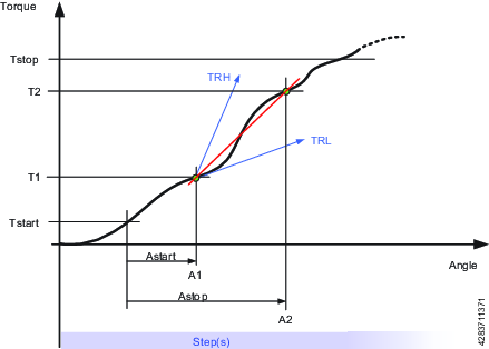
TRD – Torque Rate and Deviation
This step monitor measures and checks the torque rate, i.e. the ratio of torque vs. angle. The calculated torque rate is checked if it is within the torque rate limits defined by High Limit and Low Limit.
Parameter | Description |
|---|---|
Trigger Torque | Torque of the angle start point. |
Start Point Angle | When Start point angle has been measured from Trigger torque the measuring of the torque starts. |
End Point Angle | Angle point where the measuring of the torque is stopped. |
End Point Torque | Torque where the measuring of the torque is stopped. |
Low Limit | Lowest acceptable torque. |
High Limit | Highest acceptable torque. |
Limit | Must be > 0 |
Tstart = Torque from where AngleStart starts
Tstop = Torque where the measuring of the torque is stopped.
Astart = When AngleStart has been measured from TorqueStart the torque starts to be measured.
Astop = Angle point where the measuring of the torque is stopped.
TRL = Low Limit
TRH = High Limit
The following monitors are not supported:
Monitor | Description |
|---|---|
CL | Click - N/A |
LD | Loosening Detection - N/A |
Overview of Available Step Restrictions
To make sure the tightening stops if something unexpected happens, it is possible to add restrictions to the multistep tightening program. These restrictions could, for example, test that a maximum torque is not reached or that a part of the multistep tightening does not take too long to run. Each step has its own set of mandatory step restrictions and optional step restrictions. The mandatory restrictions are included when dragging a new step to the multistep program. All steps can have up to four restrictions each.
The following restrictions are automatically added to every step that is added to the multistep tightening program:
Step Restriction | Applicable Steps |
|---|---|
Maximum Time | All |
Maximum Torque |
|
Maximum Angle |
|
CTh – Cross Thread
This restriction checks the angle from the point where torque passes Start torque (T1) to the point where the torque passes End torque (T2). If the angle measured from Start torque (T1) is higher than Maximum limit (Amax), the tool is stopped immediately.
When the torque passes End torque (T2), the measured angle is checked against the limit Minimum limit (Amin). If the angle is lower than this limit, the tool is stopped immediately.
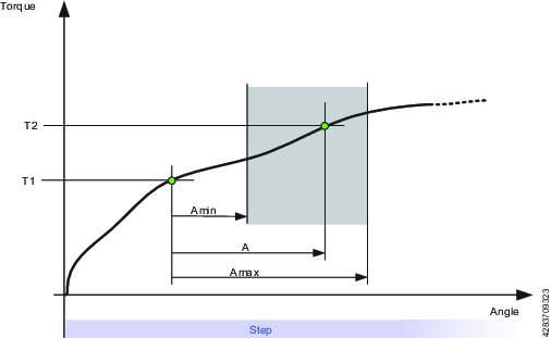
Parameter | Description | In illustration |
|---|---|---|
Start Torque | Must be <=0. | T1 |
End Torque | Must be <=0. | T2 |
Minimum Limit | The low angle limit. | Amin |
Maximum Limit | The high angle limit. | Amax |
A – Maximum Angle
This restriction measures the angle. If the measured angle reaches the Maximum Limit, the tool is stopped immediately. The angle is measured from the start of the restriction or, if specified, from the point where the torque passes Trigger Torque for the first time during the restriction.
Parameter | Description |
|---|---|
Trigger Torque | If specified, this is the torque from where the angle is measured. |
Maximum Limit | If this limit is reached the tool is stopped immediately. |
T – Maximum Torque
This restriction checks the torque. If the measured torque exceeds the Maximum limit, the tool is stopped immediately.
Parameter | Description |
|---|---|
Maximum Limit | If the torque reaches this specified limit the tool is stopped immediately. |
Ti – Maximum Time
This restriction checks the time. If Maximum Limit is reached, the tool is stopped immediately.
Parameter | Description |
|---|---|
Maximum Limit | If this time is elapsed, the tool is stopped immediately. |
Rh – Rehit
This restriction checks the torque. If the measured torque exceeds the Detection Torque, the tool is stopped immediately and the program jumps to the end of the program. It is only possible to add step Rehit restriction to the first step of the multistep tightening program. Once the Rehit restriction has been added to the first step it shall not be possible to move the step to any other position within the tightening program. The Rehit restriction has to be deleted from the first step in order to move it to other position in the tightening program.
Parameter | Description |
|---|---|
Detection Torque | If the measured torque exceeds the Detection Torque, the tool is stopped immediately and the program jumps to the end of the program. Must be greater than zero. |
RT – Rescinding Torque
This restriction checks the torque and if the measured torque drops below the condition of the restriction the tool is stopped immediately and the program jumps to end of the program. There are two methods of Rescinding Torque Restrictions for Torque and Angle control processes
Parameter | Description |
|---|---|
Type | Torque control processes or Angle control processes. Torque control processes: Torque control processes checks the torque. If the measured torque drops below the Rescinding Torque Limit the tool is stopped immediately and the program jumps to the end of the program. For the restriction to be active the torque must first exceed 110 % of the Rescinding Torque Limit Angle control processes: This restriction checks the maximum torque reached during the restriction. For the restriction to be active the torque must first exceed the Trigger Torque. If the measured torque drops below the maximum torque for longer time than Rescinding Torque Time the tool is stopped immediately and the program jumps to the end of the program. |
Rescinding Torque Limit | Default: 10 Nm. Must be > 0. |
TG – Torque Gradient
This restriction checks the gradient and if it is outside the limits the tool is stopped immediately and the program jumps to the end of the program.
Parameter | Description |
|---|---|
Gradient Angle Window | Specifies Angle Window:
|
Angle Window | Available when Gradient Angle Window is set to Manual. Must be > 0 and <= 100. |
Trigger Torque | Must be > 0 and < Tool MaxTorque. |
Damping | Frequency in which the gradient is being calculated. Must be > 0 and < 100 and < Angle window. |
Minimum Limit | Must be >= -100. |
Maximum Limit | Must be > -100 and > Low limit. |
Torque Filter Type | The type of the filter:
|
Cut-off Frequency | Needs to be specified when Torque Filter Type is set to Low pass:
|
Number of Samples | Needs to be specified when Torque Filter Type is set to Sliding Average:
|
TAW – Torque in Angle Window
This restriction checks that the measured torque in the Angle Window Length is between the Torque limits. If the measured torque is outside the limits the tool is stopped immediately and the program jumps to the end. The Angle Window Length starts at the Start Angle from the point that the torque first passed the Trigger Torque. If Trigger Torque is not set, then the Start Angle begins at the start of the restriction.
If the end of the Angle Window Length is not reached, the status of the restriction is NOK.
Parameter | Description |
|---|---|
Trigger Torque | Must be >= 0 |
Start Angle | Must be >= 0 |
Window Length | Must be >0 |
Minimum Limit | Must be >= 0 |
Maximum Limit | Must be <= Minimum limit |
TCD - Torque vs Current Deviation
This restriction verifies that all current measurements converted to the corresponding torque are, at most, the Maximum deviation away from the actual torque measured with the torque transducer. The restriction starts when the torque reaches Trigger Torque for the first time during the step and is active until the step reaches its target.
If Trigger Torque is never reached, the monitor will report OK.
Parameter | Description |
|---|---|
Trigger Torque | Must be >= 0 |
Maximum Deviation | Default: 1, Must be > 0 |
Tightening Program Properties
General settings
Parameter | Description |
|---|---|
Name | A user-defined name for the multistep program. |
Thread Direction | Direction of the threads, either clockwise or counterclockwise |
Loosening Program | Indicate if a loosening program is available. Choose from the list of available loosening programs in the software. |
Type | Type of program, either Tightening or Loosening |
Program Start | Sets the torque level for generating a result. If left blank, the result is generated every time the tool is started; otherwise result is only generated from the set torque level. |
True Angle Compensation | Tools equipped with a gyro can measure the tool rotation during tightening. If the tool is rotated during tightening, the angle measurement may be corrupted. This leads to faulty tightening if made to angle references. With True Angle Compensation the tool can compensate for these rotations and make a correct tightening. Only tools equipped with a gyro have the capability to measure the tool rotation. True Angle Compensation is not supported for ICB tools. True Angle Compensation is not supported for tools with a crowfoot (Gear Front Attachment) installed. |
Program Monitor
Parameter | Description |
|---|---|
Angle | Turn angle monitoring On or Off for the entire program. If Active in steps and Trigger Torque are left blank, angle monitoring will start at program start. |
Active in steps | Sets a range of steps the angle monitoring is valid for. If no end step is specified, angle monitoring will stop at the last step of the program that is not a Socket Release step. |
Type | Type of angle monitoring. Choose between:
|
Trigger torque | Sets the value of the trigger torque for angle monitoring. |
Low limit | Sets angle monitoring (program) lower limit |
High limit | Sets angle monitoring (program) higher limit |
Program Restrictions
Parameter | Description |
|---|---|
Maximum Time Limit | Set amount in seconds. This restriction checks the total time for the tightening and if it exceeds the Time High limit the tool is stopped immediately. The time is measured from the start of the program. |
Maximum Torque Limit | This restriction checks the torque and if the measured torque exceeds the Torque High limit the tool is stopped immediately. |
Validation
During the configuration of tightening programs, the entered values are compared with the tool capability values to prevent parameters being outside the selected limits. User-defined maximum values are useful if many different tools are being used.
Parameter | Description |
|---|---|
Validate against tool values | On: entered values are compared with the tool capability values Off: no validation performed |
Tool | Shows the tool to compare the values with. |
Attachment Tuning
Attachment tuning gives the possibility to compensate for front attachments on the tool. The compensation can be made for each tightening program.
An operator can hot swap attachments and then select a tightening program tuned for that specific attachment.
Parameter | Description |
|---|---|
Use Attachment Tuning | Yes or No |
Gear Ratio | The Attachment gear ratio is needed to compensate the angle. Minimum: 0.5 Maximum: 3.6 Socket rotation speed = Tool speed / gear ratio |
Efficiency Tuning | Attachment gear ratio combined with the Efficiency tuning is needed to compensate the torque. Minimum: 0.5 Maximum: 1.0 For example 0.9 means 10% efficiency loss. |
Configuring a Tightening Program
Adding a Tightening Program
Go to Tightening in the home menu and select Multistep program library in the left pane.
Select the plus icon and choose the appropriate type of program in the dialog box (Tightening or Loosening).
Continue with adding steps, monitors, and restrictions to the program in the tightening area.
A maximum of 16 steps can be added to a tightening program.
Deleting a Tightening Program
Go to Tightening in the home menu and select Multistep program library in the left pane.
Select the multistep tightening program that is to be deleted.
In the program itself, at the bottom left, select Delete.
Confirm by selecting Yes in the dialog box.
Creating a Multistep Program
To create a multistep program, drag and drop steps, monitors and restrictions in the tightening area.
Steps can only be placed between the start and end points of the program, whilst monitors and restrictions can only be placed on steps.
Function | Description | |
|---|---|---|
Start and end points |  | Start and end points of the multistep program. All steps must be placed between these two points. |
Adding a step |  | Drag a step from the list and drop it in the desired position between the start and end points. |
Moving a step |  | Click and hold a step and move it to the desired position |
Showing step properties |  | Click on the step to reveal the properties |
Closing step properties |  | Click anywhere in the tightening area to close the properties menu |
Deleting a step |  | Open the step properties and click Delete at the bottom of the menu |
Adding a restriction/monitor |  | Drag a restriction/monitor from the list and drop it on the appropriate step. |
Moving a restriction/monitor |  | Click and hold the icon (checkmark for monitor, stop sign for restriction) and drag and drop it on the appropriate step |
Showing restriction/monitor properties |  | Click on the restriction/monitor icon to reveal the properties menu |
Closing restriction/monitor properties |  | Click anywhere in the tightening area to close the properties menu |
Deleting a restriction/monitor |  | Open the restriction/monitor properties and click on Delete at the bottom of the menu |
Step error |  | When a validation error occurs in a step, that step will be marked. Note that when the step properties are opened, the parameter causing the error will also be marked. |
Monitor/Restriction error |  | When a validation error occurs in a monitor or restriction, that monitor or restriction will be marked. Note that when the monitor/restriction properties are opened, the parameter causing the error will also be marked. |
Forbidden placement |  | When a particular placement (of a step, monitor or restriction) is not allowed, the placeholder icon will not be shown. |
Working with the Batch Sequence Tab
Batch sequences are used to perform a specified number of tightenings in a specific order.
The tightening order can either follow a fixed scheme, or be left to the operator to decide in a free-order scheme. In either case, the sockets or signals can be used to communicate between the tool and the operator.
A Batch is set up to perform a specified number of consecutive tightenings using the same tightening program. Batches must have tightening program and batch size specified in order to run.
A Batch Sequence is an ordered set of batches, when the operation requires a combination of batches/tightening programs.
A batch sequence can consist of up to 99 batches, with a batch size of up to 250 tightenings. The batches in a batch sequence are carried out in the order listed, or by using a socket selector to choose which batch to run.
A batch sequence is completed (and the tool may be locked) when either:
All tightenings have been completed with an OK or NOK result.
The Sequence Abort Timer signal terminates the task. Unperformed tightenings are reported with NOK result.
Batch Sequence Settings
The Batch Sequence menu shows the details of a single batch sequence with the following configuration items:
Name: Sequence name and index number.
Settings: Parameters for controlling the flow and order of tightenings.
Batch Configuration: Function for creating the batch sequence from individual tightening programs. A batch consists of one single tightening program that is repeated a number of times.
Parameter | Description |
|---|---|
Name | The batch sequence name consists of an index number combined with optional characters. The index position cannot be changed. A new configuration is given lowest possible available index number. The index number is important when using sources and identifier numbers to be part of the task selection process. |
Parameter | Description | Default Value |
|---|---|---|
Lock tool on Batch sequence compl. | A batch sequence is completed when the batch sequence counter is equal to the batch sequence size. On: The tool is locked and a tightening program or batch sequence must be selected to continue performing tightenings. Off: After completion, the batch sequence is ready to be repeated. | On |
Free order | No: The configured batches will be executed in the order listed, provided they have been configured to perform tightenings. If socket has been specified, the system will prompt for the socket when the batch is to be performed. Yes: The configured batches can be executed in any order. The operator must indicate to the system which batch is to be executed by using a Socket selector. A batch is regarded as complete when all joints have been completed. | No |
Increment on NOK | Makes it possible to increment the batch counter value even though the tightening is reported as NOK. For Max consecutive NOK to work (the maximum number of times a single bolt can be tightenened), Increment on NOK must be set to No. Setting this parameter to Yes, will allow the sequence to move on to the next tightening. | No |
Max consecutive NOK | Maximum consecutive not OK (NOK) tightenings are a defined maximum allowed number of NOK consecutive tightenings in a batch. If the Max consecutive NOK number is reached, the event Too many NOK tightenings (4020) is displayed. | 0 |
Decrement on OK loosening | Decrements the counter within the currently active batch. Completed batch cannot be decremented. Never: The setting is off. Counter is not decremented when loosening is performed in the active batch. Always: decrements the counter in the active batch when loosening, if the last tightening was OK. When last tightening is OK: decrements the counter when performing a loosening in the active batch, regardless of the previous tightening result. | Never |
Sequence abort timer | On: The selected batch sequence can be aborted within a specified time limit Off: The selected batch sequence cannot be aborted. | Off |
Abort time | Time in seconds. | 10 s |
Parameter | Description |
|---|---|
Tightening program | The tightening program to use with the batch. |
Batch size | Number of tightenings the batch will perform. Max. number of tightenings in one batch is 99. Batch size 0 will give the batch an infinite number of tightenings. |
Identifier number | When using a socket selector, this is the socket position used to activate the batch. |
Adding a New Batch to a Batch Sequence
Go to Batch Sequence in the home menu. The workspace displays a list of batch sequences.
Select the plus icon in the top right corner.
Issue the batch sequence with a name.
Select the relevant parameters in the settings.
Select Batch Configuration > Edit.
Select a Tightening Program for the batch.
Enter the Batch Size, that is, the number of tightenings the batch will consist of.
Enter an optional Identifier Number.
The new batch sequence will be issued the first free position in the sequence list. If there are no free slots it will be placed at the bottom of the list and assigned the lowest available index number. It is not possible to change the index number to rearrange the batch tightening order.
Deleting a Batch from a Batch Sequence
Go to Batch Sequence in the home menu. The workspace displays a list of batch sequences.
Select the Batch Sequence to be deleted.
In the bottom of the workspace, select the Delete button.
When a batch is deleted from the batch sequence, the index sequence is compressed and updated, leaving no gaps. The index number of the deleted batch sequence will be assigned automatically to the next sequence that is created.
Working with the Sources Tab
External signals used as tasks for tightenings are configured in the Sources menu. Sources are accessories or similar connected to a virtual station. Two types of source tasks are available:
Source Tightening task: used to select a single tightening program.
Source Batch task: used to select a batch sequence, that is, a series of tightening programs.
Source Tightening
Source tightenings link a specific tightening program to an identifier number. When the identifier number is sent to the tool (either by external digital signal, or, in cases where a socket selector is used, by lifting the corresponding socket in the selector) the linked program will run over and over until a different signal is sent (or socket is picked up). There is no batch counting.
To link separate lists to the virtual station, a source task must be assigned to the virtual station. Go to Integrated Controller Tool > Virtual Station in the home menu and select Task > Change task.
Source Tightening Properties
Parameter | Description |
|---|---|
Name | The name issued to the source tightening. |
Selector mode | Control mode: An external source selects a tightening program by requesting an identifier number. The identifier number is linked to a corresponding socket in the socket selector, and by lifting the socket the tightening program is selected Confirm mode: The socket selector cannot be used as a controlling source. In this mode identifier numbers are linked to both a tightening program and a specific socket (indicated in an additional column in the list). When an identifier number is requested (by an external signal), the corresponding socket is prompted in the socket selector and the tightening program is activated when the operator lifts the socket (other sockets are disabled). If no socket is specified (that is, set to 0 in the Socket column), the tightening program is activated directly and the socket status is ignored. |
Max consecutive NOK per program | On: The batch will advance even if a NOK tightening is performed. Off: Set Max consecutive NOK for the tightening. The batch will only advance if a successful tightening is performed. |
Max consecutive NOK | Set the number of consecutive NOK results to be allowed. If the value is set to 0, there is no check performed for NOK tightenings. When reaching max consecutive NOK, the tool locks and the sequence execution is halted. |
Batch control | Select how the source tightening is to be executed. Internal: Configure how many times a source tightening is to be repeated. External: Configure how many times a source tightening should be executed by using Open protocol or an external protocol. Any configuration change clears the source tightening to start over from a clean and known state (the batch count in the batch will be reset to 0). Ongoing tightenings are able to finish before the changes take effect. |
Configuring a Source Tightening
Go to Sources in the home menu, and select Tightening in the left pane.
Select the plus icon in the top right.
Issue the source tightening with a Name and select the correct Selector mode (Control or Confirm, depending on what is required).
Max consecutive NOK can be set per source tightening or per individual program included in the source tightening. Set Max consecutive NOK per program parameter to Yes or No, depending on what is required:
To set the max consecutive NOK per source tightening, set Max consecutive NOK per program to No. Set the value in the Max consecutive NOK field.
To set the max consecutive NOK per program, set Max consecutive NOK per program to Yes. For every program in the Identifier selector configuration section, set the value in the Max NOK column.
By default, only one editable identifier number will be available when creating a new source tightening. At the bottom of the screen, select the plus icon to add more.
Give every item an identifier number.
If a socket selector is used, the identifier numbers will correspond to the positions in the socket selector, that is, identifier number 1 corresponds to socket number 1 in the socket selector.
Choose a tightening program to link to each identifier number by selecting a row and choosing from the list of tightening programs.
Source Batch
Configuring a Source Batch
Go to Sources in the home menu and select Batch Sequence in the left pane.
Select the plus icon in the top right.
Issue the source batch with a Name.
Set the Abort on new identifier to Yes if scanning a new identifier string should abort the previous scan.
Select the Identifier method (Strings for text, or Number for numerical values)
If the Identifier method is set to Strings, continue with the following steps:
Set Free order to On if the strings should be able to be scanned in any order.
Identifier strings can be made up of up to four different strings. When free order is set to Off, the strings must be scanned in a specific order for the system to recognize the string.
If required, add an identifier string by selecting the plus icon in the Identifier string configuration section.
Select the Name label for the identifier string that is to be changed. In the dialog box, the following properties can be indicated per string:
Name - the name of the string
Length - the length of the string. See Combining Identifier Strings for more information on concatenating strings.
Significant positions - the relevant positions in the string. See Significant Positions to Read in Barcode String for more information on significant positions.
Saved positions - which positions are to be logged by the system. See Saved Positions for more information about Saved positions.
The ID number (1−4) in the string properties window cannot be altered, but can only be used to navigate between the different strings.
An error may occur when Free order is set to On, and the lengths of the different strings are duplicated. The scanned sequence will then not activate a tightening program. To remedy this error, set Free order to Off, or adjust the string lengths.
Select Edit in the bottom of the Identifier String Configuration field.
In the Edit window, indicate which strings (in the String contains column) that are to be linked to which batch sequence (in the Activates column). Select the plus icon at the bottom to add more strings.
Wildcards can be used when typing the "string contains". The wildcard(s) can be used at any position in the string. No batch sequence is activated in case of an ambiguous matching result.
The wildcard is a . (period)
Significant Positions
Significant positions are used to specify which characters in the barcode string to read when putting together the string to match with your pre-defined string. The number of significant positions must match the number of characters in the pre-defined strings.
Significant Positions to Read in Barcode String
The positions in the barcode string are associated with a number between 1 and 1024. The first position of the string is 1 and the last is 1024.
The significant positions must be specified following the rules described in the table below.
Description | Significant positions | Valid configuration | Barcode string to match with pre-defined string |
|---|---|---|---|
Significant positions in order | 1,2,3,7,8 | Ok | ABCGH |
Significant positions in optional order | 7,1,2,3,8 | Ok | GABCH |
Range of numbers | 1–3,7-8 | Ok | ABCGH |
Combining Identifier Strings
The identifier string is used for matching a combination of up to four strings from a factory management system or up to four scanner inputs that need to be combined into one string.
The plus and minus buttons manage how many strings that are combined. The following parameters are available:
Parameter | Description |
|---|---|
Name | The string must be given a name. |
Length | The length of the string must be known and must be entered. This is important to be able to combine the correct string identifier. |
Significant positions | The comma-separated positions or ranges (separated by hyphen) in the combined string that are used for matching. |
Saved positions | The comma-separated positions or ranges in the strings that will be saved in the result. |
The start and end parameters in each row define the individual string positions in the combined string identifier, that is used in the next step of the matching process.
The first part in the task selection process when using an identifier string as an input, is to define which positions in the string that are to be activated:
Enter the significant positions, to define which positions in the identifier string that will be used for matching. The positions must be either comma-separated, or by range.
Saved Positions
Saved positions is a field where the user can indicate which parts of each string used in the Source Batch will be saved, and how they will be represented in the log. In this field, indicate the positions in the string that need to be saved. Positions can constitute only parts of the entire string. If the field is left empty, the entire (concatenated) string will be saved. The table below shows some examples of saved position combinations.
Saved position values are comma-separated (without spaces), and ranges are indicated using a hyphen.
Identifier string | Positions |
|---|---|
String 1: 1234567 | 1-7 |
String 2: abcdef | 8-13 |
String 3: GHIJKL | 14-19 |
String 4: 890 | 20-22 |
Saved positions | Saved results |
|---|---|
(empty) | 1234567abcdefGHIJKL890 |
1-3,9,11,15,20-22 | 123bdH890 |
8-12,1-7,19,20-21 will be changed automatically to: 1-12,19-21 | 1234567abcdeL89 |
Working with the Configurations Tab
Configurations of the tool and its accessories are made in the Configurations menu.
Tool Configuration
The following section describes how different tool functions, such as LEDs and buttons, can be configured.
1. Function Button
The function button on the tool can be configured to control up to six available input signals. The button’s three possible condition states are combined with the two possible states of the direction switch.
The function button is not available for ICB tools.
Go to Configurations in the home menu and select Tool Configurations > Edit.
Select 1. Function Button > Edit.
Set the parameters as applicable:
Function Button States
Direction Switch State
Pressed
CW
Single push
CW
Double push
CW
Pressed
CCW
Single push
CCW
Double push
CCW
Each of the six input signal combinations can be assigned one of the following items:
Item
Abort sequence
Acknowledge events
Activate tool scanner
Batch decrement
Batch increment
Bypass tightening program
Master unlock
Reset batch
Reset batch sequence
Reset too many NOK
Select next identifier number
Select previous identifier number
Unlock tool on complete
Unlock tool on disable
Set the Detection Interval parameters:
Parameter
Description
Default Value
Push detection interval
For single push: the maximum push time (in milliseconds) between the button being pressed and the button being released.
300 ms
Next push interval
For double push: the maximum time (in milliseconds) between the button being released after the first push, and the button being pressed again.
300 ms
2. LED Ring
The tool LEDs have the following features:
The blue LED is located next to the LED ring. An output signal can be connected to the LED and provides an output message to the operator.
The LED ring consists of a red, a yellow and a green ring. Output signals can be connected to the LEDs and provide output messages to the operator.
A result indicator uses the LED rings. Tightening result signals can be connected to the LEDs and provide output messages to the operator at the end of the tightening.
An output signal can be of the type Event or of the type State.
A state signal is active as long as the state is active.
An event signal is active during a programmable time range.
Blue LED
The blue LED is a single LED with a steady signal.
Select the signal that shall be connected to the blue LED from a shortcut menu.
For a signal of the type Event, select the duration of the signal.
Result Indicator
A pre-configured pattern can be selected from a shortcut menu. This pattern can be a combination of tightening results.
Select the signal message that is to be displayed from a shortcut menu.
Signal
Description
None
No LEDs are activated after the tightening, regardless of the result
Red:high:yellow:low
Either a red LED indicates the final value is too high, or a yellow LED indicates the value is too low, if the tightening is terminated incorrectly (NOK).
Red:NOK:yellow:low
A red LED indicates that the tightening is terminated incorrectly (NOK). An additional yellow LED can indicate if the value is too low.
Red:NOK
A red LED indicates that the tightening is terminated incorrectly (NOK). No additional LEDs are shown.
Red:high(Prio):yellow:low
If NOK reason is that High target angle/torque has been reached the High indication will suppress any Low indication
Select the duration of the signal.
An LED is turned on when a tightening is terminated and the LED is part of the result indicator configuration.
An LED is turned off when a tightening has been performed and the LED is not part of the result indicator configuration.
An LED is turned off when the maximum time is exceeded after a tightening has been performed.
An LED is turned off when the next tightening is started.
An LED is turned off and replaced by another LED signal pattern when an LED ring configuration is activated by an output signal.
LED Ring
The LED Ring consists of three circles of LED lamps, red, yellow, and green. Each circle can have a steady signal or a flashing signal. This provides a total of six different signals that can be connected to the LED ring.
Select the signal that is to be connected to the LED color and select input item from a shortcut menu.
For an input item of the type Event, select the duration of the signal.
An LED is turned on only when no tightening is ongoing and when the controlling output signal is activated.
An LED is turned off when the maximum time is exceeded. Only applicable if the signal type is an Event.
An LED is turned off when the next tightening is started.
An LED is turned off when the controlling output signal is deactivated. Only applicable if the signal type is a State.
3. Direction Switch
The direction switch on the tool can be configured to trigger one input signal when quickly switched from clockwise (CW) to counter clockwise (CCW) and back, or vice versa.
Go to Configurations in the home menu and select Tool Configurations > Edit.
Select 3. Direction Switch > Edit
Select Input and choose an item from the list.
4. Buzzer
The buzzer can be configured to emit different sounds. Output signals can be mapped to each of the signals and provides an audio interface to the operator.
The buzzer is configured by assigning a sound to a signal selected from a list of available signals. A signal with a sound can be prioritized between 1 and 10 where 1 is highest priority and 10 the lowest. By default a signal and sound has the priority 5.
Up to 20 different signals can be mapped to a sound and each sound can have its own characteristic profile, with parameters described in the table below. For two simultaneous signals, the signal with the highest priority overrides the other signal.
A buzzer signal runs until termination and is not interrupted by a higher prioritized signal.
Go to Configurations in the home menu and select Tool Configurations > Edit.
Select 4. Buzzer > Edit
Select the plus icon to add a new sound configuration to the table.
Set the parameters as applicable:
Parameter
Description
Priority
10 different priority levels are available for the sounds where one (1) is the highest priority level. Default priority level is five.
Frequency (0Hz, 400Hz - 4000Hz)
Exact frequency in Hz.
Time On
Time (in ms) that the buzzer emits a sound.
Time off
Time (in ms) that the buzzer is quiet.
Repeats
Number of times the buzzer repeats the on/off sequence.
Volume
The buzzer volume, in percentage of max volume.
General Settings
Item | Description |
|---|---|
Inactivity timeout | On: In order to save battery time there is an option to automatically turn off the tool after a certain time of inactivity. Off: The tool will not be turned off due to inactivity. |
Inactivity timeout | Time in minutes. Enter a value between 1-1440 minutes. |
Front LED | On: Front LED is lit when the tool trigger is pressed. Off: Front LED will always be off. |
Duration after trigger released | Front LED duration in seconds, starting when the tool trigger is released |
Tightening program selection | On: LED ring provides visualization of currently selected tightening program in a sequence. Off: Function deactivated. |
Start Condition
The way to start the tool is configurable via the Start source setting. The default value is Trigger only.
Item | Description |
|---|---|
Trigger only | Press the tool trigger to start the tightening. |
Safety Trigger | Two triggers (as with trigger and push) activated within 500 ms from each other to start the tightening. |
Accessory Bus
Tool accessories are connected to the tool through the accessory bus.
Accessory Type | Description |
|---|---|
TLS Tag | Tool Location System tag used to provide output signaling to the operator. |
EHMI | A small display and buttons used to select tasks or programs according to the configuration. |
Scanner | Barcode scanner. |
TLS Tag
The Tool Location System (TLS) tag is a tool accessory. The TLS tag is installed on the tool and connected to the tool accessory bus. The TLS tag is part of the Ubisense positioning system and is handled independently from the tool. In addition to the positioning, the TLS tag can be used to provide information to the operator. Selected output signals can generate different LED light combinations.
Up to 10 different output signals can be mapped to a light priority.
If there are two simultaneous signals, the signal with the highest priority takes precedence. When two signals with the same priority trigger the LED, the first signal received takes precedence.
Parameter | Description |
|---|---|
Signal | Select a signal to trigger the LED light from a shortcut menu. For a signal of the type Event, select the duration of the signal. |
Color | Select a color for the LED. |
Priority | 10 priority levels are available for the sounds where one (1) is the highest priority level. Default priority level is five (5). |
An output signal can be of type Event or of type State.
A state signal is active as long as the state is active.
An event signal is active during programmable time.
EHMI
The EHMI is a tool accessory. It is installed on the tool and connected to the tool accessory bus. It has a graphical display, three function buttons, and an optional scanner. The display is a subset of the IxB Software web user interface, with the possibility to select tightening programs, batch sequences, and to view results from tightenings.
In the EHMI configuration it is possible to decide if the function buttons are On or Off.
Parameter | Description |
|---|---|
Enable function button | On: The function buttons have full functionality to configure settings within the visible menus. Off: The function buttons can only be used to acknowledge a necessary dialog on the EHMI. |
Scanner
The Scanner is a tool accessory. It is installed on the tool and connected to the tool accessory bus.
In the scanner configuration it is possible to decide if the scanner should have pass through mode On or Off.
Configuring a Socket Selector
The Socket Selector is a socket tray with LEDs that assists the operator in selecting the correct socket for the tightening procedure, for example, a batch sequence. When using more than one tightening program, it is convenient to use a selector. When a socket is lifted, the corresponding tightening program is selected.
Several socket selectors can be connected to the virtual station.
To connect the socket selector to the virtual station, go to Integrated Controller Tool > Virtual Station > Accessories and select Choose Accessories.
To set up the socket selector, refer to the Socket Selector Product Instructions.
Go to Configurations in the home menu and select Socket selector in the left pane.
Issue the configuration with a Name.
Select Edit.
Select Add or Remove for the correct number of socket slots. Select all the slots that are to be active (indicated in blue).
Set Control to External if the socket selection is to be controlled by an external system.
Configuring an I/O Expander or an I/O Hub
To set up an I/O Expander, refer to the I/O Expander Product Instructions.
To set up an I/O Hub, refer to the I/O Hub Software User Guide.
Go to Configurations in the home menu and select I/O Expander in the left pane. Select Edit.
Two lists are displayed, one for Inputs and one for Outputs.
To set a channel to an input, select the required channel in the Inputs list. Choose signal type in the appearing list.
To set a channel to an output, select the required channel in the Outputs list. Choose signal type in the appearing list.
The I/O Hub has 8 channels compared to the I/O Expander which has 16. When configuring an I/O Hub, make sure that no channel is set to both an input and an output signal at the same time. One of the corresponding input and output channels must be configured to None. Select None in the appearing dialog box. Close the appearing list of items without selecting anything.
General Virtual Station
Go to Configurations in the home menu and select General Virtual Station in the left pane.
Give the configuration a name and select Edit.
In the Result filter for reporting field, set the switch to On for those parameters that are to be included in the results. By default, all parameters are set to On.
The following parameters can be set in the Result filter for reporting field:
Loosening
Batch increment
Batch decrement
Reset batch
Bypass tightening program
Abort sequence
Reset batch sequence
In the Tightening Settings, configure when to disable loosening and when to disable tightening after a tightening.
Parameter
Description
Unlock tool on loosening
Off, On OK, Always
Disable loosening
Off, On OK tightening, On NOK tightening, Always
Disable tightening
Off, On OK tightening, On NOK tightening, After every tightening
Configuring Result Presentation Settings
The Result Presentation Settings window allows a user to show the final torque without the PrT compensation value included, and PrT compensation value on the Live results.
Configure the Result Presentation Settings Window
On the Home view, select the Configurations tab. Then, on the left, select General Virtual Station.
In the wanted Configuration window, select Edit.
The Edit Configuration screen appears.In the Result Presentation Settings window, set the relevant switches to ON or OFF depending on the wanted results.
If the Show PrT Compensation Value on Live Result switch is set to ON, the Live Results window displays the PrT compensation value.
If the Show Final Torque with PrT Compensation switch is set to ON, the Live Results window displays the final torque with the PrT compensation included.
Setting the switches in the Results Presentations Settings window to either ON or OFF has no impact unless:
The multistep program has a tightening step including a Prevailing Torque step monitor with the Compensation switch set to ON.
Result Presentation Settings
Here are the different configuration options in the Results Presentations Settings window.
Show PrT Compensation Value on Live Result: ON Show Final Torque with PrT Compensation: ON | Show PrT Compensation Value on Live Result: ON Show Final Torque with PrT Compensation: OFF | Show PrT Compensation Value on Live Result: OFF Show Final Torque with PrT Compensation: ON | Show PrT Compensation Value on Live Result: OFF Show Final Torque with PrT Compensation: OFF |
|---|---|---|---|
Hover over or point at items on image to see if there is more information: | Hover over or point at items on image to see if there is more information: | Hover over or point at items on image to see if there is more information: | Hover over or point at items on image to see if there is more information: |
- Show Final Torque with PrT Compensation: ON / Show PrT Compensation Value on Live Result: ON
- Show Final Torque with PrT Compensation: OFF / Show PrT Compensation Value on Live Result: ON
- Show Final Torque with PrT Compensation: OFF / Show PrT Compensation Value on Live Result: OFF
- Show Final Torque with PrT Compensation: ON / Show PrT Compensation Value on Live Result: OFF
Show Final Torque with PrT Compensation: ON / Show PrT Compensation Value on Live Result: ON
Show Final Torque with PrT Compensation: ON
The Live Result window shows the Final Torque with the PrT compensation value included.
If the eHMI and ST Selector are on and configured, they show the Final Torque with the PrT compensation value included.
Show PrT Compensation Value on Live Result: ON
The Live Result window shows the PrT compensation value with the related compensation icon ( ).
).
If there are several compensation values, the compensation value applied to the latest available step appears.
Configuring the Show Final Torque with PrT Compensation and Show PrT Compensation Value on Live Result switches does not impact:
The final torque value displayed with the historical results.
The traces based on live and historical results.
The values in Open Protocol messages.
The signals.
The protocol adapters.
Show Final Torque with PrT Compensation: OFF / Show PrT Compensation Value on Live Result: ON
Show Final Torque with PrT Compensation: OFF
The Live Result window shows the Final Torque without the PrT compensation value included. Since the Final Torque does not include the PrT compensation value, it shows in italic.
Show PrT Compensation Value on Live Result: ON
The Live Result window shows the PrT compensation value with the related compensation icon ().
If there are several compensation values, the compensation value applied to the latest available step appears.
Configuring the Show Final Torque with PrT Compensation and Show PrT Compensation Value on Live Result switches does not impact:
The final torque value displayed with the historical results.
The traces based on live and historical results.
The values in Open Protocol messages.
The signals.
The protocol adapters.
Show Final Torque with PrT Compensation: OFF / Show PrT Compensation Value on Live Result: OFF
Show Final Torque with PrT Compensation: OFF
The Live Result window shows the Final Torque without the PrT compensation value included. Since the Final Torque does not include the PrT compensation value, it shows in italic.
Show PrT Compensation Value on Live Result: OFF
The Live Result window does not display the PrT compensation value and the related compensation icon ().
Configuring the Show Final Torque with PrT Compensation and Show PrT Compensation Value on Live Result switches does not impact:
The final torque value displayed with the historical results.
The traces based on live and historical results.
The values in Open Protocol messages.
The signals.
The protocol adapters.
Show Final Torque with PrT Compensation: ON / Show PrT Compensation Value on Live Result: OFF
Show Final Torque with PrT Compensation: ON
The Live Result window shows the Final Torque with the PrT compensation value included.
If the eHMI and ST Selector are on and configured, they show the Final Torque with the PrT compensation value included.
Show PrT Compensation Value on Live Result: OFF
The Live Result window does not display the PrT compensation value and the related compensation icon ().
Configuring the Show Final Torque with PrT Compensation and Show PrT Compensation Value on Live Result switches does not impact:
The final torque value displayed with the historical results.
The traces based on live and historical results.
The values in Open Protocol messages.
The signals.
The protocol adapters.
Working with the Integrated Controller Tool Tab
Virtual Station
A virtual station is a software abstraction of a controller. The IxB tool has an integrated controller with one connected virtual station. Various configurations can be assigned to the virtual station as needed. It is possible to select a task, assign accessory configurations, and set communication protocol parameters.
The selected task can either be running a tightening program, running a batch sequence or enabling the task using a source configured in the Sources menu. The task can be monitored and the result of the task can be presented together with any events that may have occurred during the operation.
Changing a License Type
Go to Integrated Controller Tool in the home menu and select Virtual Station in the left pane.
Select the Virtual station type in the License field.
Select a new type from the list.
If applicable, select Features>Edit, to add licenses for individual features.
Assigning a Task to a Virtual Station
Go to Integrated Controller Tool in the home menu and select Virtual Station in the left pane. Select Choose task or Change task in the Task menu.
Select one of the following tabs :
Tightening program: Displays a list of tightening programs available in the tool.
Batch: Displays a list of batch sequences available in the tool.
Sources: Displays a list of source tasks available in the tool.
Select a task from the list.
The task name is updated in the Task field.
The task selection using sources and identifier numbers/identifier strings, is described in detail in the Sources section.
Configuring Manual Mode in the Virtual Station
Manual mode for the virtual station is used to perform tasks while the tool is in locked mode. In cases where the tool is locked for a certain reason (e.g. because the tool is outside its TLS footprint) there still may be a need to perform certain tasks with the tool, such as performing emergency work. By configuring manual mode for the virtual station, users can determine what signals are sent when entering manual mode (Entering signals), what task can be performed while in manual mode (Secondary task), and what signals are sent when leaving manual mode (Leaving signals).
Since desired scenarios can vary between different users (i.e. which signals to send upon entry and exit and what task to perform), manual mode is fully configurable for each virtual station.
Configuration consists of three elements: entering signals, leaving signals and secondary task (note that by primary task is meant the (automatic) task that is assigned to the virtual station under Task).
Go to Integrated Controller Tool in the home menu and select Virtual Station in the left pane. Select Set manual mode in the Task field.
Select Choose task or Change task in the Secondary Task field. This determines which task that is to be run when in manual mode.
If no secondary task is set, the primary task will be used during manual mode.
All task types (tightening, batch sequence, source) can be set for the secondary task as for the primary task.
Set the entering signals to be sent by selecting the plus icon at the bottom of the Entering section.
Set the leaving signals to be sent by selecting the plus icon at the bottom of the Leaving section. See the parameters for leaving signals below.
There is a limit of 99 signals that can be set for entering and leaving.
Entering and Leaving Signals
The parameters for entering and leaving signals are the same.
There are two types of signals: Boolean and integer/string type. For Boolean type signals, an on/off (true/false) switch is used. For integer/string type signals, a text field is used where the (I/O) signal or string can be indicated.
Signal | Type | Default value |
|---|---|---|
Abort sequence | Boolean | Off |
Acknowledge events | Boolean | Off |
Activate tool scanner | Boolean | Off |
Clear results | Boolean | Off |
Disable Open Protocol Commands | Boolean | Off |
External monitored [1-8] | Boolean | Off |
Flash Tool Green Led (external protocol) | Boolean | Off |
Reset all identifiers | Boolean | Off |
Reset batch | Boolean | Off |
Reset batch sequence | Boolean | Off |
Reset bistable relay | Boolean | Off |
Reset latest identifier | Boolean | Off |
Reset Too Many NOK | Boolean | Off |
Set bistable relay | Boolean | Off |
Unlock tool on complete | Boolean | Off |
Unlock tool on disable | Boolean | Off |
Open Protocol
Under Protocols, in the Virtual Station menu, there is a list of available communication protocols depending on the current license in use. The Open Protocol is available for all licenses.
To gain access to functionality through Open Protocol, a unique port must be defined for the virtual station.
Go to Integrated Controller Tool in the home menu and select Virtual Station in the left pane.
Set the Open Protocol switch to On.
Enter the Server port number.
Enter the PLC Index value.
PLC Index is used to map where in the shared memory the Open Protocol commands are to be written. The default value is 1 but it is possible to enter values 1 to 6
Choose the action to be applied when the connection to the client is lost.
The Disconnect setting controls the action applied when a connection error occurs:
None - The tightening program continues normally.
Lock tool active high - The tool is locked after finishing the current tightening normally.
Unassign task - The tightening is aborted after finishing the ongoing task. Except for plain tightening programs or Batch sequences where the task will be removed after finishing.
Always lock tool - The tool is locked after finishing the current tightening, regardless of result.
Set Use legacy counter to Yes or No, depending on what i required.
By setting the counter to Yes, the legacy counter counts all tightenings in a sequence and outputs that number to secondary systems.
Select the MID2500 loosening program and select a MID2500 loosening program from the list.
Select Apply.
Choosing Accessories
Go to Integrated Controller Tool in the home menu and select Virtual Station in the left pane.
Select Choose accessories in the Accessories field.
Choose the accessory to be connected: Socket Selector, Scanner, I/O Expander or I/O Hub.
In the Configuration column (left), select the configuration to be used with the accessory .
In the Connected Accessories column (right), select the accessory to use.
Go to Integrated Controller Tool in the home menu and select Virtual Station in the left pane.
Select Choose accessories in the Accessories field.
In the Assigned Accessories list, select the minus icon next to the accessory to be removed.
Tool
View Tool Information
Go to Integrated Controller Tool in the home menu and select Tool in the left pane.
Expand the Tool Information field to view the following information:
Information
Description
Model
Tool model denomination.
Max speed
The maximum rotation speed of the tool (rpm).
Gear ratio
The ratio of the angular velocity of the input gear to the angular velocity of the output gear.
Serial number
The serial number of the tool may be needed when for the correct spare parts list or service instructions.
Max torque
The maximum torque the tool can use for a tightening.
Product number
The product number of the tool.
Health
The Health view shows information tool temperature.
The tool temperature is monitored continuously. Supported temperature units are degrees Celsius (°C) and degrees Fahrenheit (°F), with °C being the default unit. It is possible to switch between the two units without requiring a tool restart. When the tool motor temperature or tool electronics temperature exceeds max temperature, the tool is locked and an alert (2014) will be shown. The tool is once again unlocked when the tool temperature drops below the temperature limit.
Go to Integrated Controller Tool in the home menu and select Tool in the left pane.
Both tool electronics temperature and tool motor temperature are listed under Health.
Select either entry to access a list of peak temperatures and their timestamps.
Maintenance
The tool stores a service interval number and counts how many tightenings that can be performed before a tool maintenance or service is needed.
Go to Integrated Controller Tool in the home and select Tool in the left pane.
Expand the Maintenance field. The following information is displayed:
Parameter
Description
Last service
Date and time when last service was performed. The Last service date is set at the repair workshop. The Last service date is set to current date and time when the Reset service counter button is pressed.
Total tightenings at service
Total number of tightenings performed by the tool since it was used for the first time. This value is made available at service, and will remain the same until next service.
Remaining tightenings
Total number of tightenings left until the service interval is reached.
Service interval
Number of tightenings to be performed between two service events. Can be set in multiples of 10 000.
Reset service counter
Reset of the Remaining tightenings counter and sets Last service date to current date.
Set a value in the Service interval field.
The Service interval number can only be set in multiples of 10 000. Any number other than multiples of 10 000 will be rounded off to the nearest multiple of 10 000.
Select OK.
To enable the maintenance alarm, go to Settings > Alarms > Maintenance and set the Service alarm indicator to On.
Tool Calibration
Tool calibration is used to control how well a tool corresponds to a reference transducer.
The calibration value stored in the tool memory is used to adjust the torque value given by the tool’s torque transducer so that the correct torque value is displayed in the user interface. The interface displays the date when the tool was last calibrated.
Preparing the Calibration
Make sure the tool is set up to perform tightening. Set up the tool with a torque reference transducer such as an STa6000, STpad or JSB Bench. Refer to the torque reference transducer’s user guide for set-up instructions.
Choose a tightening program with a target torque corresponding to a tightening normally used with your tool.
The calibration value to use for the tool is calculated from the torque readings from the tool and the torque reference transducer by using the equation below:

Go to Integrated Controller Tool in the home menu and select Virtual Station > Tool > Calibration
Note the old calibration value found in the Calibration value: Main text box.
Make at least three tightenings and use the torque values read from the tool and the reference transducer (ACTA or similar) for calculating the mean torque values.
Calculate the new calibration value using the New calibration value equation.
If applicable, type a new date in the Next calibration date field.
Store the new calibration value in the tool memory by entering the calculated value in the Calibration value: Main text box and select Apply.
After calibration is completed, perform a tightening to verify that the new values are correct.
To enable the calibration alarm, go to Settings > Alarms > Calibration and set the Calibration alarm to On.
Calibrating a Tool with STa6000 or STpad
Performing the QA Calibration through the STa6000 or STpad
Go to the Integrated Controller Tool menu and select Tool > QA Calibration.
Set the QA Calibration to On.
Select the connection type to be used (TCP or COM), and type the port number.
The default port for communication is 4561.
Start the calibration from the STa6000/STpad. The STa6000/STpad requests tool information and tightening program.
Single tightening programs cannot be used for calibration purposes. Make sure a batch program is selected.
Execute the tightening. When the calibration device detects a tightening, it requests the tightening result from the tool.
Repeat the above step until all tightenings in the batch have been executed.
Once completed, the STa6000/STpad creates a report, as well as calculate a new calibration value for the tool.
Select Store in the STa6000/STpad to send the new calibration value to the tool.
During calibration, if the tightening program is changed, or the sequence/batch is updated, the calibration is terminated.
There is no limit in the batch size used for calibration purposes. However, the STa6000 can only display two digits as batch size. Thus, the counter on the Sta6000 reads 00 for 100.
After calibration is completed, perform a tightening to verify that the new values are correct.
Motor Tuning
A motor tuning adjusts the tool’s motor control unit to optimize the performance and minimize loss.
The motor tuning will take approximately two minutes to perform and will rotate the spindle in both clockwise (CC) and counterclockwise (CCW) directions before it is finished.
For tools configured with open end Gear Front Attachment (GFA):
Remove the open end extension from the tool before performing the motor tuning.
Go to Integrated Controller Tool in the home menu and select Tool > Motor Tuning.
Select Perform and then press the trigger on the tool.
Follow the instructions on the screen and keep pressing the tool trigger until the motor tuning is done.
If the motor tuning was successful an OK event will be displayed.
If the motor tuning was not successful, or the tool trigger was released before the motor tuning was finished, an NOK event will be displayed.
Open End Tuning
The open end tuning function is available for tools configured with open end Gear Front Attachment (GFA). The function calculates the true gear ratio of both the tool and the extension combined, and saves it to the tool. The tuning will take approximately two minutes to perform.
When the open end tuning is completed the tool must be calibrated with the open end extension attached.
Go to Integrated Controller Tool in the home menu and select Tool > Open End Tuning.
Select Perform and then press the trigger on the tool.
Follow the instructions on the screen and keep pressing the tool trigger until the open end tuning is completed.
If the open end tuning was successful an OK event will be displayed.
If the open end tuning was not successful, or the tool trigger was released before the tuning was finished, an NOK event will be displayed.
IAM
The Intelligent Application Module (IAM) is a non-volatile storage that is located in the tool. The storage module contains all the tool programs, configurations and results.
Go to Integrated Controller Tool in the home menu and select IAM.
Apply a Name to the tool.
Software Versions
Two software versions can be installed in the tool simultaneously. Installing a second version of the software is useful when performing upgrades on multiple tools. When production is ready for switching to the upgraded software, activation of the new software version is done from the IxB Software user interface, or with ToolsTalk 2.
Changing software versions does not transfer the tool configurations or tightening programs.
Software Activation
The tool can store two installed software versions. By using the Software activation, it is possible to choose which software version to use.
Make sure to keep the battery connected to the tool throughout the procedure.
Go to Integrated Controller Tool in the home menu and select Software in the left pane.
Select Current or Stored in the Software Activation window.
The tool is automatically restarted for the activation to take effect.
Update Software Version
Make sure to keep the battery connected to the tool throughout the procedure.
Go to the Integrated Controller Tool menu and select Software in the left pane.
Go to the Software Update field and select BROWSE.
Browse and choose the zip file with the applicable software and follow the instructions to finish installation.
Hardware
Go to Integrated Controller Tool in the home menu. Select Hardware in the left pane.
Select Main Board or Power Module to view Serial number, Article number and Hardware revision of the hardware module.
Exporting and Importing Configurations
The export and import functions are used to export events and tightening results for analysis in external programs, as well as allowing for transferring of tightening programs, batches, and tool configurations between tools.
The export function is used to:
Export tightening results and events for further processing.
Export log files for debug assistance from an Atlas Copco service engineer.
Export tool configuration that can be used to copy settings to another tool.
Go to Integrated Controller Tool in the home menu. Select Export/Import in the left pane.
Select what to export from the tool: All information or Settings and configurations.
When Settings and configurations is chosen no file with results or events will be exported into the archive. With this setting the export takes less time to perform.
Select EXPORT. A prompt to select where to save or retrieve the exported file is shown.
Go to Integrated Controller Tool in the home menu. Select Export/Import in the left pane.
Select IMPORT. When using the import function, all settings for tightening program, batch, accessories, and tool are replaced by the settings from the import file. However, settings for network, PIN, and results and events are not imported.
Select CONTINUE in the dialog box to start the import.
Exported Information and File Format
The exported file is a compressed file archive containing the following files:
All information
IXBExport_<datetime>_Results.csv
IXBExport_<datetime>_Events.csv
ExportInfo.txt
settings/settings.bin
atlas_tool_i.zip
atlas_sys_i.zip
atlas_subsystems_info.zip
atlas_plc.zip
jsonConfigurations.zip
Settings and configurations
ExportInfo.txt
settings/settings.bin
jsonConfigurations.zip
File | Description |
|---|---|
IXBExport__<Tool name>_<Time stamp>_Events.csv | A semicolon-separated file containing the following information:
|
IXBExport__<Tool name>_<Time stamp>_Results.csv | A semicolon-separated file containing the following information:
|
ExportInfo.txt | Information about the tool set-up and tool software. |
settings/settings.bin | A binary file containing all tightening programs and Batch settings, Accessory configurations, and tool settings such as: Language, Torque units, Date and time, and Result appearance. |
atlas_tool_i.zip | Tool logs (for debugging) |
atlas_sys_i.zip | Logfiles from IT application |
atlas_subsystems_info.zip | Info about subsystem software |
atlas_plc.zip | PLC configuration |
jsonConfigurations.zip | Multistep Tightening and Loosening programs |
Depending on the language setting in the IxB Software, the exported .csv file uses different characters to separate the fields. Depending on the language setting in the computer, formatting problems may occur when opening the exported .csv file. To avoid problems, always match the language used in the tool with the language of the computer.
See the following table for language formatting details of the IxB Software:
Language | Date/time | Field delimiter | Number format |
|---|---|---|---|
English (en_US) | MM/dd/yyyy hh:mm:ss | , | 123.456 |
Czech (cs_CZ) | dd.MM.yyyy hh:mm:ss | ; | 123,456 |
German (de_DE) | dd.MM.yyyy hh:mm:ss | ; | 123,456 |
Spanish (es_ES) | dd/MM//yyyy hh:mm:ss | ; | 123,456 |
French (fr_FR) | dd/MM/yyyy hh:mm:ss | ; | 123,456 |
Korean (ko_KR) | yyyy-MM-dd hh:mm:ss | , | 123.456 |
Italian (it_IT) | dd/MM/yyyy hh:mm:ss | ; | 123,456 |
Japanese (ja_JP) | yyyy/MM/dd hh:mm:ss | , | 123.456 |
Portugese (pt_BR) | dd/MM/yyyy hh:mm:ss | ; | 123,456 |
Russian (ru_RU) | dd.MM.yyyy hh:mm:ss | ; | 123,456 |
Swedish (sv_SE) | yyyy-MM-dd hh:mm:ss | ; | 123,456 |
Chinese (zh_CN) | yyyy/MM/dd hh:mm:ss | , | 123.456 |
Automated Backup
The Automated Backup window enables or disables sFTP export.
By default, Enable sFTP export switch is set to OFF.
When turning ON Enable sFTP export switch, an export file is created 10 minutes after the last configuration change.
If Enable sFTP export switch is set to ON on system startup, an export file is automatically created within 2-3 minutes. The export file is created within 2-3 minutes to reflect changes that might have been done before the system was shutdown.
The old Backup file is deleted before the new Backup file is available.
The data in the exported file include all configurations and settings of the controller.
The sFTP users can retrieve the exported file stored in the following directory of the system: /Export/<export file name>.
A system supporting sFTP is needed.
To retrieve the file sFTP users do not need to use any password.
The username for sFTP users is as follows:
Username | autoexport |
Working with the Settings Tab
Network Configurations
The tool can be set up to be accessed wirelessly from a web browser on a Local Area Network (LAN), using IPv4 protocol.
There is an option to use the tool as a client or an access point for other devices
Remove the cover of the tool's USB connection port.
Connect the tool to the USB-port of the PC.
Open a web browser and type in the address of the IxB Software user interface: 169.254.1.1.
Configuring Channels
Go to Settings in the home menu and select Network in the left pane.
In the Channels field, choose frequency (2.4 GHz or 5 GHz) and select Edit.
Choose to enable or disable channels.
Configuring a Wireless Client
Go to Settings in the home menu and select Network in the left pane.
In the Wireless Client field, select Edit.
Set Enabled to On.
Set DHCP to On or Off depending on the configuration. If set to Off, fill out the required information, provided by the local system administrator:
IP address
Subnet mask
Gateway
Enter a Network name (SSID).
In the Security field, select Mode and choose a security mode from the list. If WPA2 Personal is chosen, enter a Security key.
Enter security parameters and import cert files and keys, as applicable.
Edit the Optional Settings as applicable.
Select Apply.
The tool will establish a wireless connection to the network, indicated with the tool's blue connection LED indicator emitting a steady light.
To access the user interface wirelessly, type the IP address into a web browser.
Configuring the Tool as a Wireless Access Point
If multiple channels have been configured previously in Wireless Client mode, enabling Wireless AP mode will update the channel list to contain only the current/default channel for the Wireless AP mode.
Go to Settings in the home menu and select Network in the left pane.
In the Wireless AP field, select Edit.
Set Enabled to On.
Enter the required information, provided by the local system administrator:
IP address
Subnet mask
Gateway
To distribute IP addresses, set DHCP Server to On and enter IP range start and IP range stop.
Enter a Network name (SSID).
In the Security field, select Mode and choose a security mode from the list. If WPA2 Personal is chosen, enter a Security key.
Select Apply.
Server Connections
The tool can be set up to communicate with servers running the following Atlas Copco software products:
ToolsTalk − used to configure one or several controllers and IxB tools
ToolsNet − used to handle result reporting
Atlas Copco License Manager
Configuring the ToolsTalk Connection
Go to Settings in the home menu and select Server Connections in the left pane.
In the ToolsTalk field, set the following parameters:
Field
Description
On/Off
Enables/Disables communication with the ToolsTalk server
Server port
ToolsTalk server port
Server host
ToolsTalk server IP address
Select Apply.
To view the ToolsTalk connection status, go to Reports > Results and select the  button. In the appearing dialog box, select the Server connections tab.
For information on how to configure ToolsTalk, refer to the ToolsTalk 2 User Guide.
Configuring the ToolsNet Connection
Go to Settings in the home menu and select Server Connections in the left pane.
In the ToolsNet field, set the following parameters:
Field
Description
On/Off
Enables/Disables communication with the ToolsNet server
Server port
ToolsNet server port
Server host
ToolsNet server IP address
Select Apply.
To view the ToolsNet connection status, go to Reports > Results and select the button. In the appearing dialog box, select the Server connections tab.
For information on how to configure ToolsNet, refer to the ToolsNet 8 User Guide.
Configuring the License Manager Connection
Go to Settings in the home menu and select Server Connections in the left pane.
In the Atlas Copco License Manager field, set the following parameters:
Field
Description
On/Off
Enables/Disables communication with the Atlas Copco license manager server
Server port
Atlas Copco license manager server port
Server host
Atlas Copco license manager server IP address
Select APPLY.
Preferences
Date and Time
Date and time must be set in order for events and results to get the correct time stamp for when they occurred. The time is retrieved from one of three available sources:
Manual − the date, time, and time zone are set manually.
NTP − the date and time are retrieved from an NTP (Network Time Protocol) server defined in the user interface.
ToolsNet − the date and time are retrieved from the ToolsNet server.
Go to Settings in the home menu and select Preferences in the left pane.
In the Date and Time field, set the following parameters:
Parameter
Description
Source
Source to retrieve the time from.
NTP Server 1
IP-address of an NTP server providing date and time for the tool.
Server 1 status
OK/No Status
NTP Server 2
IP-address of an NTP server providing date and time for the tool.
Server 2 status
OK/No Status
Date
Date entered manually if the source is set to manual.
Time
Time entered manually if the source is set to manual.
Time zone
The time zone; either the location or a standard time zone such as UTC (coordinated universal time)
Select APPLY.
Setting Language
The user interface is available in the following twelve languages:
English
Czech
German
Spanish
French
Korean
Italian
Japanese
Portuguese
Russian
Swedish
Chinese
Go to Settings in the home menu and select Preferences in the left pane.
In the Language field, select the language currently in use and choose a language from the list.
The language change will take effect immediately.
Setting the Torque Unit
Torque results are displayed in the chosen unit both after a tightening is performed and when stored in the results list.
Unit | Description |
|---|---|
cNm | centinewton metre |
dNm | decinewton metre |
Nm | newton metre |
kNm | kilonewton metre |
in·lbf | inch-pound force |
ft·lbf | foot-pound force |
in·ozf | inch ounce-force |
ft·ozf | foot ounce-force |
gf·cm | gram-force centimetre |
kgf·cm | kilogram-force centimetre |
kgf·m | kilogram-force metre |
Go to Settings in the home menu and select Preferences in the left pane.
In the Torque Units field, select the unit currently in use and choose a unit from the list.
The torque unit change will take effect immediately.
Setting the Temperature Unit
Go to Settings in the home menu and select Preferences in the left pane.
In the Temperature Units field, select the unit currently in use and choose C° or F° from the list.
Setting the Startup Screen
The default screen at startup of the tool is the Home screen. It is possible to change startup screen to the Result screen. A change of startup screen in the settings requires a restart of the tool or a refresh of the user interface.
Go to Settings in the home menu and select Preferences in the left pane.
In the Startup Screen field, select the startup screen currently in use and then select Home screen or Result Screen from the list.
Configuring the PIN Settings
Using a PIN code prevents unauthorized usage of the tool or accidental changes. Multiple users can be added to the tool, each with its own PIN. Note that PIN codes are not linked to tool configurations but are used mainly for logging reasons.
The PIN must be a four-digit number in the range 0000–9999. When PIN is enabled, and the configured inactivity time has been reached, the tool configuration cannot edited. A maximum of 10 users can be added to the tool.
When changes are made to the PIN, the user that made the changes is logged. This will be displayed in the column Changed by, and added to the change history.
When PIN is activated a PIN code is required when accessing the tool from the web user interface. Without the correct PIN being entered, the user interface will only be readable, but not editable.
Go to the Settings in the home menu and select PIN in the left pane. Select Configure.
Set the PIN code switch to On.
The PIN can only be activated when at least one user in the list is enabled. If no user is enabled, a warning will appear.
Fill out the Inactivity timeout (in seconds) to set when the tool will be locked in case of inactivity.
The default value for Inactivity timeout is 120 seconds. Note that this is a global setting, and cannot be set on a per user basis.
Go to Settings in the home menu and select PIN in the left pane. Select Configure.
Select the plus icon in the top right.
Select the Name field to edit the entry.
In the User window, enter a Name .
Enter PIN and Confirm PIN for the user. The PIN must be a four-digit number in the range 0000–9999.
The PIN in both fields (Enter PIN and Confirm PIN) must match for the changes to be applied.
Select Permissions. The list of the available configurations appears.
Select the check box at the left of the necessary configuration(s) the user can access and make changes.
After selecting the necessary configuration(s), select OK.
The User window appears.Select all selects all the available configurations at the same time.
Select Deselect all to clear the check boxes and undo the selection.The user can access and make changes only to the configuration(s) selected in the Permissions window, and browse the unselected configurations with read-only access. For the unselected configurations, no changes are allowed.
Select Apply.
In the list of users, select the check box to the left of the user name to enable the user.
When PIN is enabled, the tool locks automatically after the configured Inactivity timeout.
To disable a PIN/user, clear the check box to the left of the user name.
Go to Settings in the home menu and select PIN in the left pane. Select Configure.
In the Users field, select the check box to the left of the user name to enable the user.
When the PIN is enabled, the tool locks automatically after the configured Inactivity timeout.
To disable a PIN/user, clear the check box to the left of the user.
Note that PINs can also be enabled and disabled by selecting the user name and setting the Enabled switch to On or Off, respectively.
Go to Settings in the home menu and select PIN in the left pane. Select Configure.
In the Users field, select the red minus icon to the right of the user name.
Select the padlock icon in the top right corner.
A dialog box with a key pad appears. Enter the PIN code and select OK.
When the PIN is enabled and the screen has been unlocked, an Open Padlock icon appears in the top right corner of the user interface.
The user interface can be locked again manually, by selecting the Open Padlock icon.
Configuring Alarms
Alarms are set to control when to perform maintenance or calibration of the tool.
The tool service interval, calibration details, and other relevant information is found in the Integrated Controller Tool > Tool menu.
Go to Settings in the home menu and select Alarms in the left pane.
In the Maintenance field, set the following parameters:
Parameter
Description
Service indicator alarm
On/Off: Enables/Disables an alarm for when the service interval of the tool is reached.
Tool lock after alarm
On/Off: Enables/Disables a lock of the tool when the service interval is reached.
Go to Settings in the home menu and select Alarms in the left pane.
In the Calibration field, set the Calibration alarm to On/Off to enable/disable it.
Configuring Events
Each event has a default setting for whether it is to be acknowledged (ACK), logged (LOG), or displayed (DISP).
Some options cannot be changed. They are greyed out.
Go to Settings in the home menu and select Events in the left pane.
Select Configure events.
Search for the event to be configured by typing the event code in the Search field and pressing Enter.
Tick or untick the boxes ACK., LOG. and DISP., as desired.
If applicable, add information about the event in the DETAILS field.
Performing Factory Reset and Clearing Results
The tool can be reverted back to its original factory settings.
All settings, configurations and historical data will be deleted when the tool is reset. Only perform a factory reset when you are completely sure that this course of action is required.
Go to Settings in the home menu and select Reset in the left pane.
In the Factory Reset Controller field, select the Reset button.
A dialog box will appear warning that all data will be deleted. Select Yes.
The tool will perform a reboot to activate the new settings.
Go to Settings in the home menu and select Reset in the left pane.
In the Clear Results field, select the Clear button.
A dialog box will appear warning that all results and events will be deleted. Select Yes.
The tool will perform a reboot to clear the data.
Reports and Statistics
In this section, you can learn about available reports and statistics.
Working with the Reports Tab
Viewing Results
This section describes how to access tightening results from the tool, and how to read the information given in the different result views.
When a tightening is performed, the result is stored in the tool. Results can also be sent to an external system such as ToolsNet, or exported for analysis using the export function. For more information about statistical analysis, result filtering and tightening analysis using ToolsNet, refer to the ToolsNet User Guide.
Live Results and Stored Results
The live result dialog box shows results from the tool on the screen as it occurs. Tightening results are also automatically stored in the tool as soon as the tightening is finished.
Each task is displayed as one result. A single tightening can show results in a table with key parameters or as a tightening graph. A batch sequence shows all the individual tightenings in the order in which they were performed.
Live Results View

Position | Description |
|---|---|
1 | Target torque |
2 | Tightening result |
3 | Tightening result |
4 | Target angle |
5 | Result status |
6 | An NOK tightening will give a detailed status of the unsuccessful tightening. |
7 | Number of completed batches in the sequence |
8 | Batch sequence name |
9 | Total number of batches in the sequence |
10 | Result of each completed batch in the sequence:
|
11 | Number of completed tightenings in the batch |
12 | Tightening program name |
13 | Total number of tightenings in the batch |
14 | Number of completed tightenings in the batch:
|
Stored Results View
The tool stores the result for every tightening or loosening performed.
Go to Reports in the home menu and select Results in the left pane.
Select View all results. The result list will show information about:
Date: date and time of the tightening performed.
Tightening Program: Tightening Program column shows Multistep Tightening Program name, or Batch Sequence name followed by the Tightening Program name within the Batch Sequence.
Result: Torque / Angle result.
Limits: Limits column shows only when the user sets Step Monitor or Step Restriction (Step level), or Program Monitor or Program Restrictions (Multistep Program level).
Step Monitors, Step Restrictions, Program Monitors and Program Restrictions are applicable for Final Torque and Final Angle.
Details: Tightening / loosening result details.
Trace checkbox: By selecting a trace checkbox the corresponding result will be shown in the Sync Trace Result View.
Results marked with a red bar have status NOK. For descriptions of NOK results, see the NOK Result List.
Select a result in the list to enter the Trace Result View.
The Trace Result View window shows, step by step, the tightening life-cycle.
When the tightening is NOK, the Trace Result View shows which Step Monitor or Step Restriction that caused it.
On the upper-right corner of the trace graph, select the left-arrow / right-arrow to show the necessary trace graph.
The following trace graphs are available:
Torque / Time
Torque / Angle
Angle / Time
Speed / Time
Speed / Angle
Gradient / Time (when the tightening program is configured to make a gradient trace)
Gradient / Angle (when the tightening program is configured to make a gradient trace)
Current / Time
Current / Angle
On the trace graph, it is possible to zoom in/out, move the trace, and read x-axis and y-axis values on a specific point.
On the lower-left corner of the trace graph, select "+" to zoom in , "-" to zoom out, or the "square icon" to reset the zoom level back to the default view.
On the lower part of the Trace Result View window, detailed step information is shown.
Viewing Synchronized Traces
Synchronizing traces older than software version 3.5 is not supported.
Go to Reports in the home menu and select Results in the left pane.
Select View all results.
Select the traces to compare by marking the
 icon of the corresponding results. A selected trace icon turns blue.
Up to 10 traces can be selected.
Results without the
icon do not support synchronization.Select the
 icon in the upper right hand corner, to open the sync trace view. When selecting the
  icon all selected result traces will be unchecked.
In the Sync Trace Result View, select the preferred Sync method from the drop-down list.
Select the trace types with the arrows in the upper right hand corner.
The Sync Trace Result View is shown below:
1 | Select method to synchronize traces and display of current sync method. |
2 | Zoom methods to examine sections of the traces in more detail. Select "+" to zoom in , "-" to zoom out, or the "square icon" to reset the zoom level back to the default view. It is also possible to zoom to a specific section by holding down the right mouse button, moving the mouse over a section, and release the right mouse button. The area inside the drawn rectangle defines the area to show. |
3 | Each result is represented by one tab, showing the time when the tightening was performed. An icon on the left of each tab reflects the outcome of the tightening:
Clicking on the icon toggles between the following display settings for its trace:
|
4 | Change primary result trace. The primary result trace is used as reference and will define the values for the x-axis. Only one trace can be set as primary result. The first selected trace (the left-most tab) is by default used as reference. |
5 | Tightening details of currently selected result. |
6 | Switch between available trace types. The following trace graphs are available:
|
Sync Methods
Sync methods are different strategies to synchronize traces by a specific value.
Traces can be synchronized by, for example, peak torque (highest torque reached for each trace). This shifts all traces along the x-axis, until each curve has its peak torque value at the exact same position on the x-axis.
All subsequent results are given an offset on the x-axis according to one of the following methods:
Sync method | Description |
|---|---|
None | Default value. Selected traces are not synced. |
Peak / Torque | All traces are synchronized towards the peak value, that is, shifted along the x-axis so that the peak values are at the same position on the x-axis as the peak value of the primary result. |
Custom / Torque |
If sync method Custom is selected and none of the traces contains the configured value, an exclamation mark is shown in the custom value field. |
If a result has no trace value that matches to the sync method it cannot be synchronized and its trace will not be shown. It will instead be shown with an exclamation mark.
If none of the traces are possible to synchronize, the error message “Unable to synchronize” is shown.
NOK Results List
Error message | Description | Required step category | Reporting step monitors | Reporting step restrictions | Reporting program monitors | Reporting program restrictions |
|---|---|---|---|---|---|---|
Drive error | Internal drive error or battery removed during tightening | |||||
Rehit | Attempt to tighten an already tightened bolt. | Rehit | ||||
Soft start torque below min | Soft start torque below minimum level. | SoftStart | Peak Torque | Torque in Angle Window | ||
Soft start torque above max | Soft start torque exceeded maximum level. | SoftStart | Peak Torque | Maximum Torque | Maximum Torque Limit | |
Rundown torque above max | Rundown torque exceeded maximum level. | Rundown | Peak Torque | Maximum Torque | Maximum Torque Limit | |
Rundown angle above max | Rundown angle exceeded maximum level. | Rundown | Angle | Maximum Angle | ||
Rundown exceeding max time limit | Rundown time exceeded maximum limit. | Rundown | Time | Maximum Time | ||
Rundown below min time limit | Rundown time below minimum limit | Rundown | Time | |||
Rundown torque below min | Rundown torque below minimum level. | Rundown | Peak Torque | Torque in Angle Window | ||
Rundown angle below min | Rundown angle below minimum level | Rundown | Angle | |||
Final step torque above max | Final step torque exceeded maximum level. | Final | Peak Torque | Maximum Torque | Torque | Maximum Torque Limit |
Final step angle above max | Final step angle exceeded maximum level. | Final | Angle | Maximum Angle | Angle | |
Final step torque below min | Final step torque below minimum level. | Final | Peak Torque | Torque in Angle Window | Torque | |
Final step angle below min | Final step angle below minimum level. | Final | Angle | Angle | ||
Tightening timeout | Tightening time limit exceeded. | Maximum Time Limit | ||||
Trigger lost | Tool trigger was released before target was reached. | |||||
Slip off | Socket has slipped off the nut. | Rescinding Torque | ||||
Post view torque below min | Post view torque below minimum level. | Post View Torque Low | ||||
Post view torque above max | Post view torque exceeded maximum level. | Post View Torque High | ||||
Post view torque interval not reached | Post view torque interval not reached. | Post View Torque Low | ||||
Torque compensation interval not reached | Torque compensation interval angle before rundown end not reached | Prevailing Torque | ||||
Current monitoring error | Torque vs current deviation exceeds maximum level. | Torque vs Current Deviation | ||||
Soft start angle above max | Soft start angle exceeded maximum level. | SoftStart | Angle | Maximum Angle | ||
Soft start angle below min | Soft start angle below minimum level | SoftStart | Angle | |||
First step angle high | First step angle exceeded maximum level | First | Angle | Maximum Angle | ||
First step angle low | First step angle below minimum level | First | Angle | |||
First step torque high | First step torque exceeded maximum level | First | Peak Torque | Maximum Torque | Maximum Torque Limit | |
First step torque below min | First step torque below minimum level | First | Peak Torque | Torque in Angle Window | ||
First step exceeded max time limit | First step time exceeded maximum level | First | Time | Maximum Time | ||
First step below min time limit | First step time below minimum level | First | Time | |||
Final step exceeded max time limit | Final step time exceeded maximum level | Final | Time | Maximum Time | ||
Final step below min time limit | Final step time below minimum level | Final | Time | |||
Soft start exceeded max time limit | Soft start time exceeded maximumlevel | SoftStart | Time | Maximum Time | ||
Current at shut off exceeds max limit | Measured shutoff current exceeding max limit | Shut off current | ||||
Current at shut off below min limit | Measured shutoff current below min limit | Shut off current |
Viewing Protocol Status
Go to Reports in the home menu and select Results in the left pane.
Select the
button in the upper right corner. The Protocol Status dialog box appears.The tabs in the dialog box show the following information:
Tab
Description
Open Protocol
Shows the status of the open protocol connection: OK / NOK
Server Connections
Shows the status of the connections to ToolsTalk and ToolsNet servers: OK / NOK
To change the configuration setting Enabled / Disabled, go to Settings > Server Connections and select the server to configure.
Launcher Status
Shows the launcher status of the different system adapters: OK / NOK
Select Close.
Viewing Events
Events are used to notify the user of certain state changes or occurrences in the system. They are divided into three types; Information, Warnings and Errors and require different kinds of actions.
Each event has a default setting for whether it should be acknowledged (Ack), logged (Log) or displayed (Disp). These settings can be configured in in the Settings menu under Events.
Go to Reports in the home menu and select Results in the left pane.
Select View all events.
Select an event in the list to open the event dialog box.
The Event Dialog Box
The event dialog box contains information about the occurred event describing what has happened, where and when.

Position | Description |
|---|---|
1 | Heading - Describes what part of the system the event concerns. |
2 | Event name - A short descriptive text of the event. |
3 | Code - A unique four-digit number that identifies the event. |
4 | Module - Describes in what part of the system the event concerns. |
5 | Type - Information, Warning or Error. |
6 | Time - Date and time when the event occurred. |
Event Codes
Events are used to notify the user of certain state changes or occurrences in the system. They are of different types and require different kinds of actions.
Some of the procedures described can only be performed by an Atlas Copco authorized service provider.
Event Code Groups
The event codes can be divided into the following groups:
Event code | Group | Description |
|---|---|---|
1000-1999 | Controller, Tool | Controller and Tool events. |
2000-2999 | Tool | Tool events. |
3000-3999 | Controller, Drive, Channel, Configuration | Controller and Drive events, and Step sync events. |
4000-4999 | Process | Tightening process events. |
5000-5999 | Configuration | Program configuration events. |
6000-6999 | Accessory | Accessory events. |
7000-7999 | Message | Messages. |
Event Code List Description
The following table describes the information in the event code list:
Item | Description | |
|---|---|---|
Event code | The unique event number. | |
Type | Type of event:
| |
Name | A descriptive name of the event. | |
Description | A short description of the event and why it occurred. | |
Procedure | If applicable the procedure contains an instruction on how to clear the event. | |
A | Acknowledge: Tells the user whether the event has to be acknowledged or not before you can proceed. The value in this list is the default value. | |
L | Log: Tells the user whether the event is to be saved in the event log or not. The value in this list is the default value. | |
D | Display: Tells the user whether the event is to be displayed on the screen or not. The value in this list is the default value. | |
Event Code List
Event | Description | Procedure | Log | Display | Ack | ||
|---|---|---|---|---|---|---|---|
Code | Type | Name | |||||
1000 | Info | Controller started | The controller is started. | N/A | X |
|
|
1001 | Warning | Controller serial number updated | Generated at start-up if IT-board box serial number (controller serial number) differs from AUX-board box serial number. AUX-board is considered to be non-replaceable in field. The controller will reboot when the serial number is updated. | Replace IT-board or box. | X | X | X |
1010 | Info | Tool connected | A tool is connected. | N/A | X | X |
|
1011 | Info | Tool disconnected | A tool is disconnected. | N/A | X | X |
|
1012 | Info | Tool connection rejected | OpenProtocol tool rejected controller connection. | Check if another controller is connected to the tool. | X | X |
|
2000 | Warning | Battery low |
| Replace battery. | X | X |
|
2001 | Warning | Battery empty |
| Replace battery. | X | X |
|
2002 | Warning | Tool battery health low | Tool battery health problem is detected. | Replace battery | X | X | |
2004 | Warning | Tool is not of the preferred type | Tool has been replaced by a tool with a different Tool max torque. | Change tool |
|
| |
2006 | Warning | Tool backup battery health low | The backup battery in the tool has too poor performance. | The backup battery should be replaced. | X |
| X |
2007 | Warning | Tool backup battery missing | Tool backup battery is missing. | Insert battery | X | X | |
2008 | Warning | Tool backup battery error | Tool backup battery error detected. | Replace battery | X | X | |
2009 | Warning | Backup battery voltage low | The controller's backup battery is almost empty | Replace battery | X | X | |
2010 | Error | Tool software version mismatch | Tool and controller software versions not compatible. | Service tool - update tool software. | X | X | X |
2012 | Warning | Tool communication disturbance | Communication between tool and controller interrupted. | Relocate antenna placement. | X |
|
|
2013 | Warning | Illegal ring position | Tool direction switch in faulty position. | If occurring frequently - service tool. | X | X |
|
2014 | Warning | Tool overheated | Tool overheated. | Allow tool to cool down. | X | X |
|
2015 | Error | Tool temperature sensor error |
| Service tool. | X | X | |
2016 | Warning | Tool pulse unit overheated | Tool pulse unit overheated. Tool is not locked, but the warning is displayed whenever the tool is started as long as the pulse unit temperature is over threshold. | Allow tool to cool down | X | X | |
2019 | Warning | Tool could not start motor | Tool motor failure. | X | X | ||
2020 | Warning | Tool requires motor tuning | Tool requires motor tuning. | Perform a motor tuning. | X | X |
|
2021 | Warning | Motor tuning failed | Motor tuning failed. | Complete motor tuning or service the tool. | X |
|
|
2022 | Info | Motor tuning completed | Motor tuning completed. | N/A | X |
|
|
2023 | Warning | The tool requires open end tuning | The tool requires open end tuning. | Perform open end tuning. | X | X |
|
2024 | Warning | Open end tuning failed | Open end tuning failed. | Try to perform open end tuning one more time. If it fails again, service the tool. | X |
|
|
2025 | Info | Open end tuning successful | Open end tuning successful. | N/A | X |
|
|
2026 | Warning | Open end position failed | Open end position failed. | Press the trigger again and wait for the positioning to be completed. If it fails again, service the tool. | X | X |
|
2027 | Warning | Usage limited due to high tool temperature | Temperature limit has been reached. Tightening has been inhibited to reduce risk for tool shutting down due to overheating. | Wait until tool temperature has been reduced. | X | X |
|
2030 | Error | Tool memory failure, change tool | Tool memory corrupt. | Service the tool. | X | X | X |
2031 | Error | Tool accessory memory corrupt | Tool accessory memory corrupt. | Service the tool accessory. | X | X | X |
2040 | Error | System check failure |
| X | X | X | |
2041 | Error | Torque transducer error | Will be generated either on calibration error or if tool reports transducer error. | Service the tool. | X | X |
|
2042 | Error | Angle transducer error |
| Service the tool. | X | X | X |
2043 | Error | Tool ground fault error |
| Service the tool. | X | X | X |
2044 | Info | Tool service interval expired | Indicates that servicing of the tool is needed. Triggered when the number of set tightenings has been exceeded. | Perform service of tool. | X | X |
|
2045 | Warning | Tool calibration data invalid | If validation of calibration data fails. | Service tool. | X | X |
|
2046 | Info | Tool, next calibration date has passed | Indicates that calibration of tool is needed. Triggered when calibration alarm is enabled in settings and the current time is greater than next calibration date. | Service tool. | X | X |
|
2047 | Info | Auto update of servicedata checksum | Indicates that service data checksum has been updated automatically. | N/A | X | X |
|
2048 | Info | Tool calibration value updated by QA device | Tool calibration was updated when a calibration with a QA device was performed | X | X | ||
2050 | Error | Tool parameter file not supported | Required tool parameters are missing. | Update tool parameters. | X | X |
|
2060 | Info | Unexpected trigger behavior | Used to prevent start of tool if accessory is connected. | N/A | X | X |
|
2071 | Error | Tool memory corrupt | Tool descriptor is corrupt. | Service the tool. | X | X |
|
2072 | Info | Unknown device connected |
| X | X |
| |
2073 | Warning | Tool trigger supervision failure | HW channel failure. Mismatch between hardware and software of tool trigger. | X | X |
| |
2074 | Warning | Tool indicator board failure | Tool indicator board failure. | Service the tool. | X | X |
|
2075 | Warning | Tool fan voltage failure | Tool fan voltage failure. | Service the tool. | X | X |
|
2076 | Warning | Tool accessory bus voltage failure | Tool accessory bus voltage failure. | Service the tool. | X | X |
|
2077 | Warning | Tool trigger sensor error | Tool trigger sensor error. | Service the tool. | X | X | |
2078 | Info | Tool Tightening program updated | Tool locked due to tightening program update. | X | X |
| |
2079 | Error | Tool cable not supported | Tool cable is corrupt. The chip in the cable is not responding or is damaged. | Switch cable. | X | X |
|
2080 | Error | Tool battery failure | DC voltage too high or too low. Battery failure. | Contact the Atlas Copco service representative and send back battery to Atlas Copco (do not reuse it!). | X | X |
|
2081 | Error | Tool current limit reached | The current limit has been reached and the drive is disabled. | Service the tool. | X | X |
|
2082 | Error | Tool current measurement error | Current measurement error. Current cannot be measured with a reliable result. | Service the tool. | X | X |
|
2083 | Error | Tool internal error | Various internal hardware errors. | Service the tool. | X | X |
|
2084 | Error | Tool internal software error | Various internal software errors. | Service the tool. | X | X |
|
2085 | Error | Tool RBU error | An RBU error was detected by the tool software. | Check that the RBU is correctly installed. If error is still present then service the tool. | X | X |
|
2086 | Error | Tool stall | Tool motor is stalling. | Service the tool. | X | X |
|
2087 | Warning | Tool motor current high | Tool motor current limit is exceeded, and the tool is locked. Tool will enter failsafe mode. | X | X | ||
2088 | Warning | Tool battery current high | Tool battery current is too high. | X | X | ||
2089 | Warning | Tool drive voltage low | Tool drive voltage is below the monitored lower voltage limit. | X | X | ||
2090 | Warning | Tool drive voltage high | Tool drive voltage is above monitored higher voltage limit. | X | X |
| |
2091 | Warning | Tool main board error | Tool main board internal error. | X | X | ||
2092 | Warning | Tool power module error | Tool power module internal error | X | X | ||
2093 | Warning | Pulse unit oil level low | The oil level of the connected pulse tool is low. | Service the tool | X | X | |
2094 | Warning | Pulse unit oil level empty | The oil level of the connected pulse tool is below required operational level | Service the tool | X | X | X |
2095 | Warning | Tool battery communication lost | Tool lost communication with battery. | Make sure battery is seated correctly. Otherwise change battery | X | X | |
2096 | Error | Tool battery software version mismatch | Tool battery software incompatible with tool software. | Update software. | X | X | |
2100 | Info | STwrench smartHead removed | STwrench smartHead has been removed. | Reconnect smartHead and restart the wrench. | X | X |
|
2101 | Warning | Wrench tightening when locked | A wrench tightening was performed when the tool status was locked in the controller. | Wait until the tool status in controller is unlocked. | X | X |
|
3000 | Error | Controller internal software error | Software error in the controller. | Contact service. | X | X | X |
3001 | Error | Controller clock battery empty | Internal battery is getting close to end of life. | Replace battery | X | X | X |
3010 | Warning | System overheated | The controller is overheated. | Cool down. | X | X |
|
3011 | Warning | Drive overheated Controller hardware | Cool down. | X | X | ||
3013 | Warning | Usage limited due to high controller temperature | Temperature limit has been reached. Tightening has been inhibited to reduce risk for controller shutting down due to overheating. | Wait until controller temperature has been reduced. | X | X | |
3020 | Warning | Controller hardware failure | X | X | |||
3021 | Warning | System voltage problem | DC voltage too high or too low. | N/A | X | X |
|
3030 | Error | IP address conflicting with another node on the network | The set IP address is in use by another device on the same network. | Change IP address on one of the devices. | X | X |
|
3031 | Info | Network cable unplugged | The carrier of the factory port is lost (cable disconnected). | Check the cable connection. | X | X |
|
3032 | Info | Pairing started | Tool pairing started. | N/A | X | X |
|
3033 | Info | Pairing successful | Tool pairing successful. | N/A | X | X |
|
3034 | Error | Pairing unsuccessful: no tool found | The controller found no tool to pair with when scanning for radio peers. | Set the tool in pairing mode and try again. | X | X |
|
3035 | Error | Pairing unsuccessful: more than one tool found | The controller found more than one tool when scanning for radio peers. | Ensure that only one tool is in pairing mode when starting the pairing mode on the controller. | X | X |
|
3036 | Error | Pairing unsuccessful: Communication error | The controller experienced a loss of connection, an unexpected answer or timeout during the pairing process. | Try to perform pairing one more time. If it fails again, service the tool. | X | X |
|
3037 | Info | Pairing unsuccessful: Tool slot is full | Clear one tool slot | X | X | ||
3040 | Warning | Emergency stop | Drive disabled due to emergency stop. | Reset emergency stop. | X | X |
|
3050 | Info | System clock updated | System clock has been updated. | N/A | X |
|
|
3051 | Error | System clock error | Wrong time read from hardware Real Time Clock (RTC). | Change RTC battery. | X | X | X |
3052 | Warning | Remote start configuration error | Mismatch between HW and SW remote start configuration. | Check and verify that HW dip switch matches the selected start source. | X | X |
|
3053 | Info | Drive connected | StepSync drive has been connected. | X | X | ||
3054 | Info | Drive disconnected | StepSync drive disconnected. | X | X | ||
3055 | Warning | Mode configuration error | Generated when selected mode is configured wrongly. E.g. configuring two bolts with the same bolt number or the same channel, incomplete mode configuration | Check Toolstalk2 for mode configuration error | X | X | |
3056 | Warning | Unable to start, tool or drive is missing | Generated when a used channel is missing a drive or tool. | Check Channel Menu on the HMI. Connect missing drive or tool. | X | X | |
3057 | Info | Unable to start, channel is already in use | Generated when a needed channel has been allocated to another virtual station | X | X | ||
3058 | info | No mode selected | Select mode | X | X | ||
3059 | Warning | Failed to connect to Atlas Copco License Manager | Indicates that the controller failed to connect to the local license manager to get licenses. | Check local network. If it fails again, service the controller. | X | X |
|
3084 | Error | Soft PLC runtime error | eCLR has terminated in an uncontrolled way. | X | X | ||
3150 | Error | Software IAM incompatibility | IAM is incompatible with the software installed on the controller. | Replace IAM. | X | X | X |
3160 | Error | Failed to activate newly installed software | Something went wrong during the activation. When the newly installed software starts, a fallback to the previous working software happens. This happens when the new software fails to start for three times and only during software installation. | Take an export and contact Atlas Copco for further assistance. Note down the software version you are trying to install as well as the software version that is working. | X | X | X |
3161 | Error | Started on unexpected software partition | The controller has started on the inactive software side and not on the expected software side. | Note down the software information (on the Home page of the controller, select Controller > Software). Try to restart the controller and make sure its running on correct software when started again. If error persists, do an export and contact Atlas Copco. | X | X | X |
3500 | Error | Generic license manager error | Inconsistency detected in the feature management system used. | Contact Atlas Copco representative. | X | X | X |
3501 | Error | License Manager Synchronization Error |
| X | X | X | |
3502 | Info | License Manager Synchronization Done |
| X |
| ||
3503 | Warning | License manager: another source in use | License is used by another source. | Check license assignment | X | X | |
3504 | Warning | License manager restart needed | Restart license manager | X | X | ||
3505 | Info | USB license synchronization started | X | ||||
3506 | Error | USB license synchronization error | X | ||||
3507 | Info | USB license synchronization done | X | ||||
3508 | Info | One or more of your licenses are about to expire. Please make sure you have a license server configured | Update licenses | X | X | ||
3511 | Warning | One of your licenses has a different license definition | Inconsistency detected in a license to be used. | Contact Atlas Copco representative. | X | X | |
3550 | Warning | License is missing | Install the correct license | X | X | ||
4010 | Info | Tool locked by digital input | The tool is locked by a digital input signal. | N/A | X | X |
|
4011 | Info | Tool locked by open protocol | The tool is locked by open protocol. | N/A | X | X |
|
4012 | Info | Tool locked by field bus | The tool is locked by the field bus. | N/A | X | X |
|
4013 | Info | Tool locked by socket selector | Tool is locked when the socket selector is disconnected from the Virtual Station. | Unlock by Master unlock | X | X | |
4014 | Info | Tool locked by Soft PLC | Soft PLC signal locked the tool. | Unlock by Master Unlock | X | X | |
4015 | Info | Loosening disabled | Loosening is disabled in the tightening program | X | X |
| |
4016 | Info | Tightening disabled |
| X | X |
| |
4017 | Info | Loosening not configured | Loosening is not configured in the selected tightening program | Select different tightening program | X | X | |
4020 | Info | Too many NOK tightenings | Maximum consecutive NOK tightenings in batch is exceeded | X | X |
| |
4025 | Info | No Tightening program selected | No tightening program selected. | Select tightening program or batch sequence. | X | X | |
4030 | Info | Batch sequence aborted | The batch sequence has been aborted. | X | X | ||
4031 | Info | Max time to complete batch sequence reached. |
| X | X |
| |
4032 | Info | Max time to complete first tightening reached. |
| X | X |
| |
4035 | Info | Locked by line control |
| X | X |
| |
4040 | Info | Locked by alternative identifier | Tool locked by alternative identifier. | X | X |
| |
4050 | Invalid socket configuration | Tightening program assigned to multiple sockets. | Tightening program assigned to multiple sockets | X | X |
| |
4060 | Info | Tool locked on batch complete | When running a batch with flag Tool lock on batch sequence complete this event is generated when the user press the trigger. | Unlock with signal Unlock Tool on complete. | X | X |
|
4070 | Info | Process enter manual mode | Indicates that manual mode has been activated for a virtual station | ||||
4071 | Info | Process enter automatic mode | Indicates that automatic mode has been entered for a virtual station | ||||
4500 | Info | Result DriveError | Internal driver error or driver loss detected. |
|
|
|
|
4501 | Info | Result Rehit | Attempt to tighten an already tightened bolt when Rehit detection is on. |
|
|
|
|
4502 | Info | Result Soft Start Torque Low | Soft start torque below minimum level. |
|
|
|
|
4503 | Info | Result Soft Start Torque High | Soft start torque exceeded maximum level. |
|
|
|
|
4504 | Info | Result Self Tap Torque High | Selftap torque exceeded maximum level. |
|
|
|
|
4505 | Info | Result Self Tap Torque Low | Selftap torque below minimum limit. |
|
|
|
|
4506 | Info | Result Safety Torque Low | Automatically calculated torque value to ensure torque sensor is mounted correctly. |
|
|
|
|
4507 | Info | Result Rundown Torque High | Rundown torque exceeded maximum level. |
|
|
|
|
4508 | Info | Result Rundown Angle High | Rundown angle exceeded maximum level. |
|
|
|
|
4509 | Info | Result Rundown Time High | Rundown time exceeded maximum limit. |
|
|
|
|
4510 | Info | Result Rundown Time Low | Rundown time below minimum limit. |
|
|
|
|
4511 | Info | Result Rundown Torque Low | Rundown torque below minimum level. |
|
|
|
|
4512 | Info | Result Rundown Angle Low | Rundown angle below minimum level. |
|
|
|
|
4513 | Info | Result Final Torque High | Final step torque exceeded maximum level. |
|
|
|
|
4514 | Info | Result Final Angle High | Final step angle exceeded maximum level. |
|
|
|
|
4515 | Info | Result Final Torque Low | Final step torque below minimum level. |
|
|
|
|
4516 | Info | Result Final Angle Low | Final step angle below minimum level. |
|
|
|
|
4517 | Info | Result Tightening Timeout | Tightening time limit exceeded. For General Tightening Strategies max tightening time is 30 seconds. For Multistep max tightening time depends on step restriction Maximum Time Limit. Error code is dependent on tightening stage. | Redo tightening. |
|
|
|
4518 | Info | Result Trigger Lost | Tool trigger was released before target was reached. For General Tightening Strategies it is not allowed to release the trigger before the tightening stage has finished. For Multistep, the error is displayed when trigger is lost before the target in a specific step is reached. |
|
|
|
|
4519 | Info | Premature torque loss | Socket has slipped off the nut. |
|
|
|
|
4520 | Info | Result Target Reached Before Final Step | Target torque reached before final step in tightening program. |
|
|
|
|
4521 | Info | Result Post View Torque Low | Post view torque below minimum level. |
|
|
|
|
4522 | Info | Result Post View Torque High | Post view torque exceeded maximum level. |
|
|
|
|
4523 | Info | Result Post View Torque Interval Not Reached | Post view torque interval not reached. |
|
|
|
|
4524 | Info | Result Torque Compensation Interval Not Reached | Torque compensation interval angle before rundown end not reached. |
|
|
|
|
4525 | Info | Result Tool movement exceeded | from a NOK tightening detailed status. |
|
|
|
|
4526 | Info | Result SafetyCurrMon Sensor Mismatch | Current monitoring error. |
|
|
|
|
4527 | Info | Result Tool movement exceeded |
|
|
|
|
|
4528 | Info | Result Soft Start Angle High | Soft start angle exceeded maximum level (Four Step). |
|
|
|
|
4529 | Info | Result Soft Start Angle Low | Soft start angle below minimum level (Four Step). |
|
|
|
|
4530 | Info | Result First Angle High | First step angle exceeded maximum level (Four Step). |
|
|
|
|
4531 | Info | Result First Angle Low | First step angle below minimum level (Four Step). |
|
|
|
|
4532 | Info | Result First Torque High | First step torque exceeded maximum level (Four Step). |
|
|
|
|
4533 | Info | Result First Torque Low | First step torque below minimum level (Four Step). |
|
|
|
|
4534 | Info | Result First Time High | First step time exceeded maximum level (Four Step). |
|
|
|
|
4535 | Info | Result First Time Low | First step time below minimum level (Four Step). |
|
|
|
|
4536 | Info | Result Final Time High | Final step time exceeded maximum level (Four Step). |
|
|
|
|
4537 | Info | Result Final Time Low | Final step time below minimum level (Four Step). |
|
|
|
|
4538 | Info | Result Final Supervision Torque Low | Final Supervision Torque was not reached. |
|
|
|
|
4539 | Info | Result Soft Start Time High | Soft start time exceeded maximum level (Four Step). |
|
|
|
|
4540 | Info | Result Soft Start Time Low | Soft start time below minimum level (Four Step). |
|
|
|
|
4543 | Info | Result Snug Monitor High | Wrench only. Monitor detected snug value exceeded. | ||||
4545 | Info | Result No Residual Torque | Wrench only. Residual torque was under threshold. | ||||
4546 | Info | Result Overspeed | Wrench only. Wrench gyro failed to measure angle due to high speed. | ||||
4547 | Info | Result Effective Loosening | Wrench only. Wrench detected unexpected loosening. | ||||
4548 | Info | Result Final Less Than Target | Final torque is below target torque set in tightening program. | ||||
4549 | Info | TurboTight time limit exceeded | TurboTight time limit exceeded. | ||||
4550 | Info | Result Rundown Pulses High | Maximum number of rundown pulses is exceeded. | ||||
4551 | Info | Result Rundown Pulses Low | Rundown is completed before the minimum number of rundown pulses is reached. | ||||
4552 | Info | Result Final Pulses High | maximum number of pulses is exceeded. | ||||
4553 | Info | Result Final Pulses Low | Tightening is completed before the minimum number of pulses is reached. | ||||
4554 | Info | Current at shutoff high | Current at shut off exceeded Current Limit High. | ||||
4555 | Info | Current at shutoff low | Shut off current measured was below Current Limit Low | ||||
4556 | Info | Uncategorized multistep error. | An error in the multistep configuration, often in conjunction with tool validation. | ||||
4557 | Info | Result overload | X | X | |||
4600 | Warning | Data Drop or Data Hold used in combination with Batch tightening. The signals have no effect. | Data Drop and Data Hold are only supported for worktasks, without batch control. Select another worktask if the signals has to be used. Valid only for Flex and StepSync. | X | |||
4601 | Info | Data Hold active: tightening result is sent once signal is low. | Valid only for Flex and StepSync. | X | |||
4602 | Info | Data Drop active: tightening result discarded. | Valid only for Flex and StepSync. | X | |||
5010 | Warning | Invalid Tightening program parameter value | The parameter in the selected tightening program are invalid. | Check the configuration of the selected tightening program to find and change the value of the parameter. | X | X |
|
5020 | Info | Main trigger is not the active start source | Generated when configured for push start only and user presses main trigger. Will be generated until user presses the push start. | Press push start to start the tool. | X | X |
|
5030 | Info | Tightening program complexity exceeds tool Capacity | The selected tightening program is too complex for the tool. Tool will be locked. | Reduce complexity of the tightening program, or choose different program | X | X | |
6010 | Info | Accessory connected | Accessory is connected to the controller. |
| X | X | |
6020 | Info | Accessory disconnected | Accessory is disconnected from the controller. |
| X | X | |
6021 | Warning | Fieldbus offline | No communication with fieldbus. | X | X | X | |
6030 | Warning | Accessory address collision | Two or more accessories with the same address are connected. | Change address on accessory. | X | X | X |
6040 | Warning | Accessory communication error | Intermittent communication error with accessory. | Check cables and connectors. | X | X |
|
6041 | Warning | Fieldbus error | Communication error with fieldbus. |
| X | X | X |
6042 | Warning | Fieldbus module mismatch | The installed fieldbus module does not match with the configured module. | Change the configuration to match with the installed module, or replace the installed module with the correct one. | X | X | X |
6050 | Info | Wrong socket selected | Generated when no or incorrect socket is selected. | X | X |
| |
6090 | Warning | Barcode scanner could not be identified | When no unique serial number is found. | Configure the barcode reader device. | X | X | X |
7010 | Info | Message text to display | General event for displaying of messages. | None |
|
| X |
8200 | Info | Failed to Open Serial Port | Serial port to be used could not be opened. | Check serial port connections. | X | ||
8214 | Error | EHMI Software version mismatch | EHMI software version does not match in compatibility with the controller. | Update the software version of the EHMI. | X | X | |
Viewing NOK Ratio
Go to Reports in the home menu and select NOK Ratio in the left pane.
Select View 10 highest NOK tightening programs.
SPC - Statistical Process Control
The purpose of the built-in SPC function is to give the operator, or quality control staff, data that lets them judge the stability and capability of the assembly process according to standard SPC rules.
By configuring the tool's SPC function it is possible to simplify and do the work directly on the tool without the need of external software.
Since it is possible to use program monitors within the tool as a SPC variable, it is necessary to specify that only variables controlled by the tool show the performance of the system. Other variables show mainly results from other processes. For example, if a torque value is applied to a joint, then SPC of the final torque value and the related results - such as Cp and Cpk - show the performance of the tool on that joint.
Statistical calculations are based on old data stored in the tool.
Configuring SPC Parameters
Go to Reports in the home menu and select Statistics in the left pane.
In the SPC Configuration window, enter the following parameters to collect results stored on the tool:
Number of Subgroups: enter the number of subgroups the statistics calculation is based upon.
The number of results (Number of Subgroups × Subgroup Size) can range from 2 through 500.Subgroup Size: enter the number of tests (samples) necessary to define each point (the average value of the tests in the subgroup) on the SPC charts.
The subgroup size can range from 2 through 25.Frequency: enter how often to start collecting a new subgroup.
Frequency must be equal or higher than Subgroup size.For instance, if Frequency is 8 and Subgroup Size is 5, the first 5 data (results) is used for the subgroup. Because of the Frequency =8, the next subgroup starts considering data (results) from the 8th one on, and so on in a loop.
Configuring SPC Variables
Go to Reports in the home menu and select Statistics in the left pane.
Select the Plus icon in the upper-right corner.
The SPC Variable window shows the new variable.In the Name box, enter the name of the variable.
The name of the variable is the heading of the SPC Variable window.Select Tightening Program.
The Tightening Program window appears and lists all the multistep tightening programs stored on the tool and available for statistical calculations.
Select the multistep tightening program of the new variable.Select Virtual Station.
The Virtual Station window appears.
Select the Virtual Station which the results are used from.Statistics are based on results made by a Virtual Station that has the following license type assigned:
Process Control
Select Monitor.
The Monitor window appears.
Select one of the following program monitors which the SPC calculation is based on:Step monitor peak torque
Step monitor angle
Final torque
Final angle
Program monitor torque
Program monitor angle
If the user selects Step monitor peak torque or Step monitor angle, in the Step number box enter the number of the necessary step of the tightening program which read the value from.
If the user uses the result reporters, it is possible to have an effect on the following monitor values: Final torque and Final angle.
Select Edit limits.
The Variable configuration window appears.
For calculations and analysis of the results, set the following limits for each value of interest.
In the Tolerance limits window, set the following limits (used for calculation of the process capabilities Cp and Cpk):
Upper Tolerance Limit (UTL): a user-defined quantity that identifies the highest acceptable value of a product attribute.
Lower Tolerance Limit (LTL): a user-defined quantity that identifies the lowest acceptable value of a product attribute.
In the Control limits window, enable or disable the Auto calculate switch.
If the Auto calculate switch is set to Yes, the control limits are automatically calculated.
If the Auto calculate switch is set to No, set the following limits:
Mean - Upper control limit: a statistically determined measurement that appears as a horizontal dashed line above the process average. Generally considered to be three times the standard deviation of the process measurements.
Mean - Lower control limit: a statistically determined value that appears as a horizontal dashed line below the process average. Generally considered to be three times the standard deviation of the process measurements.
Range - Upper control limit: a statistically determined measurement that appears as a horizontal dashed line above the process average. Generally considered to be three times the standard deviation of the process measurements.
Range - Lower control limit: a statistically determined value that appears as a horizontal dashed line below the process average. Generally considered to be three times the standard deviation of the process measurements.
Sigma - Upper control limit: a statistically determined measurement that appears as a horizontal dashed line above the process average. Generally considered to be three times the standard deviation of the process measurements.
Sigma - Lower control limit: a statistically determined value that appears as a horizontal dashed line below the process average. Generally considered to be three times the standard deviation of the process measurements.
In the Capabilities window, set the following limits:
Cp: the Cp index gives the process capability: it is the number of times the spread of the process is into the tolerance width (Upper tolerance limit - Lower tolerance limit). The higher the value of Cp, the better the process.
Cpk: the Cpk index gives the process capability corrected for the position. It is not useful having a high Cp index if the process setting is way off center in relation to the middle of the tolerance range. A high Cpk index means, then, that you have a good process with a small spread in relation to the tolerance width, and also that it is well centered within that width (Upper tolerance limit - Lower tolerance limit). If Cpk is equal to Cp, the process is set to produce exactly in the middle of the tolerance range.
Calculating Statistics
Go to Reports in the home menu and select Statistics in the left pane.
In the SPC Configuration window, enter the parameters to collect results stored on the tool (Number of Subgroups, Subgroup Size, and Frequency).
Select the Plus icon at the upper-right corner.
The SPC Variable window shows the new variable.
Configure the new SPC Variable.In the SPC Variable window, select Calculate.
Data is collected from the historical results stored in the controller that are aligned with the criteria set in the SPC Configuration window and SPC Variable window. The values of interest are collected into subgroups of the size set in the SPC Configuration window. The collected tightening results on the controller are used for statistics calculations.
It is not possible to calculate statistics for results from deleted tightening programs or Virtual Stations, unless the results are still stored on the tool.
Only one user at a time can calculate statistics.
Statistics Formulas
Data in a subgroup is calculated as:
Average:
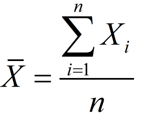
Range = R = max (Xi) - min (Xi), where i=1...n
Standard deviation for a subgroup:
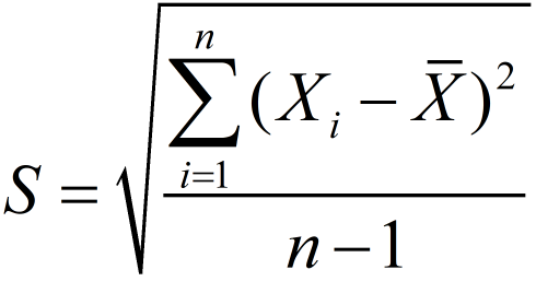
Total overall of the standard deviation:
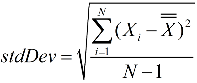
Where N = total number of observations.
When specified number of subgroups to use for calculations has been collected, the SPC function starts calculations to determine the statistical stability.
Calculations are performed through the following steps: (m = number of subgroups)
Calculation of Average of Average values:
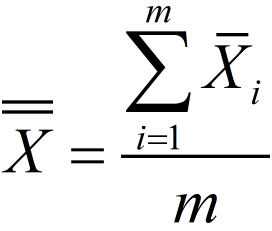
Calculation of Average of Range:
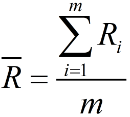
Calculation of Average of Standard deviation:
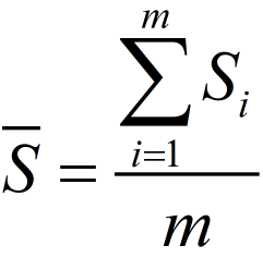
Calculation of the process capabilities Cp and Cpk with respect to Sigma:
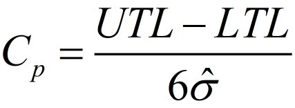
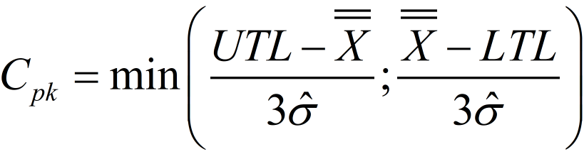
Where:
 is the overall arithmetic average of the observed characteristic values.
UTL is the Upper Tolerance Limit.
LTL is the Lower Tolerance Limit.
The sigma estimation is the mean square standard deviation within the subgroups:
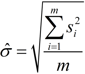
Calculation of the process capabilities Cp and Cpk with respect to Range:
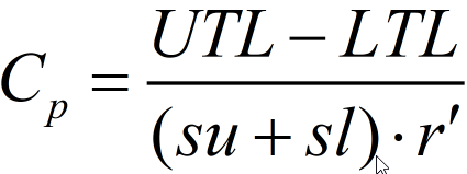
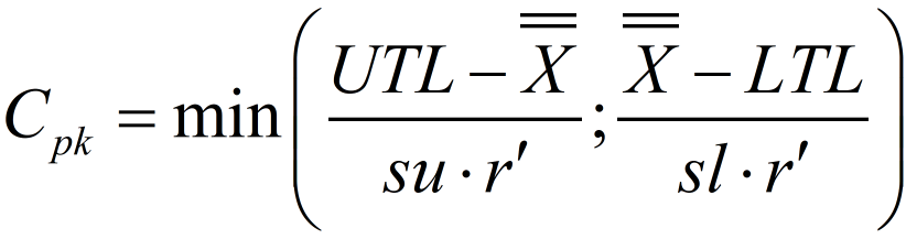
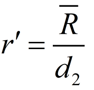
Where for a normal distribution su = sl = 3.
Calculations for control limits if, in the SPC Configuration window, the Auto calculate switch is set to Yes:
X-bar R (Mean)

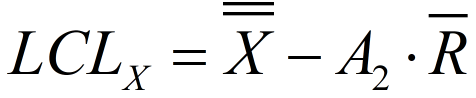
X-bar R (Range)

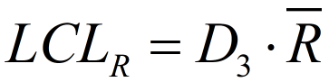
X-bar S (Mean)

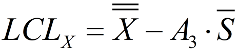
X-bar S (Sigma)

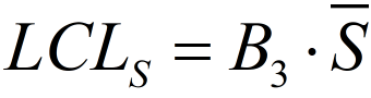
A2, A3, D3, D4, B3, and B4 are constants (for more information, see the "SPC Calculation Constants" paragraph).
SPC Calculations Constants
Subgroup Size | Divisors for estimate of standard dev. | Factors for Control Limits | |||||
|---|---|---|---|---|---|---|---|
Xbar R | Xbar S | ||||||
A2 | D3 | D4 | A3 | B3 | B4 | ||
n | d2 | ||||||
2 | 1.128 | 1.880 | - | 3.267 | 2.659 | - | 3.267 |
3 | 1.693 | 1.023 | - | 2.574 | 1.954 | - | 2.568 |
4 | 2.059 | 0.729 | - | 2.282 | 1.628 | - | 2.266 |
5 | 2.326 | 0.577 | - | 2.114 | 1.427 | - | 2.089 |
6 | 2.534 | 0.483 | - | 2.004 | 1.287 | 0.030 | 1.970 |
7 | 2.704 | 0.419 | 0.076 | 1.924 | 1.182 | 0.118 | 1.882 |
8 | 2.847 | 0.373 | 0.136 | 1.864 | 1.099 | 0.185 | 1.815 |
9 | 2.970 | 0.337 | 0.184 | 1.816 | 1.032 | 0.239 | 1.761 |
10 | 3.078 | 0.308 | 0.223 | 1.777 | 0.975 | 0.284 | 1.716 |
11 | 3.173 | 0.285 | 0.256 | 1.744 | 0.927 | 0.321 | 1.679 |
12 | 3.258 | 0.266 | 0.283 | 1.717 | 0.886 | 0.354 | 1.646 |
13 | 3.336 | 0.249 | 0.307 | 1.693 | 0.850 | 0.382 | 1.618 |
14 | 3.407 | 0.235 | 0.328 | 1.672 | 0.817 | 0.406 | 1.594 |
15 | 3.472 | 0.223 | 0.347 | 1.653 | 0.789 | 0.428 | 1.572 |
16 | 3.532 | 0.212 | 0.363 | 1.637 | 0.763 | 0.448 | 1.552 |
17 | 3.588 | 0.203 | 0.378 | 1.622 | 0.739 | 0.466 | 1.534 |
18 | 3.640 | 0.194 | 0.391 | 1.608 | 0.718 | 0.482 | 1.518 |
19 | 3.689 | 0.187 | 0.403 | 1.597 | 0.698 | 0.497 | 1.503 |
20 | 3.735 | 0.180 | 0.415 | 1.585 | 0.680 | 0.510 | 1.490 |
21 | 3.778 | 0.173 | 0.425 | 1.575 | 0.663 | 0.523 | 1.477 |
22 | 3.819 | 0.167 | 0.434 | 1.566 | 0.647 | 0.534 | 1.466 |
23 | 3.858 | 0.162 | 0.443 | 1.557 | 0.633 | 0.545 | 1.455 |
24 | 3.895 | 0.157 | 0.451 | 1.548 | 0.619 | 0.555 | 1.445 |
25 | 3.931 | 0.153 | 0.459 | 1.541 | 0.606 | 0.565 | 1.435 |
Viewing Statistics Results
Go to Reports in the home menu and select Statistics in the left pane.
In the SPC Configuration window, enter the following parameters: Number of Subgroups, Subgroup Size, and Frequency.
Select the Plus icon at the upper-right corner.
The SPC Variable window shows the new variable.
Configure the new SPC Variable.In the SPC Variable window, select Calculate.
To show the statistics results, in the SPC Variable window, select View box.
View box shows the date and time which the statistics results have been done.
The statistical results are displayed through a histogram, the XBar-R chart, and the XBar-S chart.When all calculations on the filtered results are done, they are sent to the user interface and ToolsTalk 2.
The statistics results are locally saved on a Temporary Internet Files folder (not saved on the tool).
Histogram
A histogram is a series of rectangles, each proportional in width to the range of values within a class and proportional in height to the number of samples falling in the class. A Gaussian curve follows the trend of the rectangles. A histogram reveals the amount of variation that any process has within it.
The histogram is useful because it emphasizes and clarifies trends that are not readily discernible in tables.
XBar-R Chart
The XBar-R control chart shows both the mean value (XBar) and the range (R) of a subgroup. This is the most common type of control chart using indiscrete or continuous values. The XBar part of the chart shows any changes in the mean value of the process while the R part shows any changes in the dispersion of the process.
This chart is particularly useful because it shows changes in mean value and dispersion of the process at the same time, making it a very effective method for checking abnormalities in the process.
XBar-S Chart
The XBar-S control chart shows both the mean value (XBar) Chart and the standard deviation (S).
The XBar-S chart is identical to the XBar-R chart except that the R (range) is replaced by an S (standard deviation).
Calculated Statistical Values
The calculated statistical values are displayed in information boxes below the histogram, the XBar-R chart, and the XBar-S chart.
The calculated values depend on the chart which they are read on.
The calculated statistical values are:
Min = minimum value for all collected sample values
Max = maximum value for all collected sample values
Mean =
Mean+3Sigma =
+ 3*stdDevMean-3Sigma =
- 3*stdDevCp (in XBar-R chart the value is based on range, and in XBar-S chart the value is based on sigma)
Cpk (in XBar-R chart the value is based on range, and in XBar-S chart the value is based on sigma)
Center line = in Range part
 , and in Sigma part
Target (if available the target value for the monitor)
Standard deviation = Total overall standard deviation = stdDev
Reference
In this section, you can find miscellaneous useful information.
Terms and Definitions
Term | Synonym | Definition | Note |
|---|---|---|---|
batch | multiple tightening using the same tightening program and socket | ||
batch sequence | sequence | multiple tightening using a combination of different tightening programs and sockets | |
controller feature | License for controller-wide features, such as Soft PLC and StepSync. | Are assigned to an entire controller and can be used by all virtual stations. | |
event | controller and tool status signals | ||
final angle | actual measured angle value at the end of the tightening cycle | ||
final torque | actual measured torque value at the end of the tightening cycle | ||
GUI |
| user interface made up of interactive graphical elements such as windows, icons and symbols on a display |
|
HMI | Human Machine Interface | user interface to tool or controller | The HMI can be a computer web-based interface or controller touch screen. |
IAM | Intelligent Application Module | removable module in controller containing program, configuration parameters and tightening results | |
line structure | sorting and grouping controllers in structures, folders or sub-folders in ToolsTalk | The line structure is a method for improving the visibility of a large group of controllers in a structured manner. | |
post view torque | function for monitoring and detecting torque maximum and minimum values before rundown is complete | One purpose of post view torque is the use of a self-locking nut. | |
tightening program | Parameter set | configuration of parameters and values to control and monitor a single tightening action, and to store the tightening result | |
push | transfer of data saved in ToolsTalk to the controller memory | ||
QIF | Quality Integrated Fastening | fully integrated line of nutrunners, controllers, accessories and process monitoring tools to guarantee high quality and traceability of tightening in industrial assembly systems | QIF was developed at Atlas Copco and is preferably used in motor vehicle industry and other assembly situations where many joints are critical. The QIF concept also includes process monitoring and documentation. |
QIF accessory | accessory for operator communication and guidance used in QIF | Accessory products used for communication between system and operator. For example: scanner, operator panel, stacklight and socket selector. The communication provides improved quality and traceability in the assembly process. | |
Re-hit detection | detection of re-tightening of an already tightened joint | ||
rotate | tightening strategy which rotates the tool head. | Rotate is mainly used for test or demonstration purposes. | |
rundown complete | end of the rundown step, when the screw head is in contact with the surface and the tightening step begins | ||
rundown step | step when a bolt enters the thread until the bolt head touches the surface | ||
snug | screw or bolt is approximately finger-tight to the surface | ||
socket selector | QIF accessory, consisting of a socket tray with lamps, that can be used to guide an operator to the correct socket | ||
soft start | start tightening at slow speed during a specified rotation angle | The function helps the bolt to enter the thread in a well controlled way and may prevent unwanted ergonomic tool movement when the trigger is pressed. | |
stacklight | QIF accessory, which handles the communication between operator and controller through digital signals like lamps, buttons, switches and buzzer | ||
target | desired result of a tightening | The target is expressed in torque or angle. | |
target angle | desired angle value at the end of the tightening cycle, measured from a reference point | ||
target torque | desired torque value at the end of the tightening cycle | ||
tightening step | step from when a bolt head has reached the surface until the tightening has reached the desired target torque or target angle | ||
tightening strategy | algorithm which continuously controls and monitors the tightening process | The user can select a strategy optimized for the joint and program certain parameters. | |
virtual station | virtual controller | software abstraction of a physical controller to behave like multiple controllers | A controller can have only one cable tool connected to it, but several wireless tools. Each tool is connected to its own virtual station. |
virtual station type | License containing a bundle of controller features. | This license is required for running a virtual station. | |
virtual station feature | License for individual features. | Can be used to complement Virtual station type licenses. |
Input Signals
Abort Sequence - 10012
When a Batch sequence abort request is received, the Batch sequence functionality aborts the batch sequence only after getting the ongoing tightening result.
Name in SoftPLC: ABORT_BATCH_SEQUENCE
Signal Type | Value Type | Size Min [bit] | Size Max [bit] |
|---|---|---|---|
Event | Boolean | 1 | 1 |
Devices
Fieldbus: TRUE
Indicator Box: FALSE
Internal I/O: TRUE
Operator Panel: TRUE
Tool Functions: TRUE
ST Selector: FALSE
Stacklight: TRUE
TLS Tag: FALSE
I/O Expander: TRUE
Fieldbus
Fieldbus: TRUE
Indicator Box
Indicator Box: FALSE
Internal I/O
Internal I/O: TRUE
Operator Panel
Operator Panel: TRUE
Tool Functions
Tool Functions: TRUE
ST Selector
ST Selector: FALSE
Stacklight
Stacklight: TRUE
TLS Tag
TLS Tag: FALSE
I/O Expander
I/O Expander: TRUE
Acknowledge Events - 10004
Acknowledge of an event.
Name in SoftPLC: ACKNOWLEDGE_EVENT
Signal Type | Value Type | Size Min [bit] | Size Max [bit] |
|---|---|---|---|
Event | Boolean | 1 | 1 |
Devices
Fieldbus: TRUE
Indicator Box: FALSE
Internal I/O: TRUE
Operator Panel: TRUE
Tool Functions: TRUE
ST Selector: FALSE
Stacklight: TRUE
TLS Tag: FALSE
I/O Expander: TRUE
Fieldbus
Fieldbus: TRUE
Indicator Box
Indicator Box: FALSE
Internal I/O
Internal I/O: TRUE
Operator Panel
Operator Panel: TRUE
Tool Functions
Tool Functions: TRUE
ST Selector
ST Selector: FALSE
Stacklight
Stacklight: TRUE
TLS Tag
TLS Tag: FALSE
I/O Expander
I/O Expander: TRUE
Activate Tool Scanner - 10075
Activates the tool scanner through an external source.
Name in SoftPLC: ACTIVATE_TOOL_SCANNER
Signal Type | Value Type | Size Min [bit] | Size Max [bit] |
|---|---|---|---|
Event | Boolean | 1 | 1 |
Devices
Fieldbus: TRUE
Indicator Box: FALSE
Internal I/O: TRUE
Operator Panel: TRUE
Tool Functions: TRUE
ST Selector: FALSE
Stacklight: TRUE
TLS Tag: FALSE
I/O Expander: TRUE
Fieldbus
Fieldbus: TRUE
Indicator Box
Indicator Box: FALSE
Internal I/O
Internal I/O: TRUE
Operator Panel
Operator Panel: TRUE
Tool Functions
Tool Functions: TRUE
ST Selector
ST Selector: FALSE
Stacklight
Stacklight: TRUE
TLS Tag
TLS Tag: FALSE
I/O Expander
I/O Expander: TRUE
Batch Decrement - 10002
Incrementally decreases the batch counter by one.
Name in SoftPLC: BATCH_DECREMENT
Signal Type | Value Type | Size Min [bit] | Size Max [bit] |
|---|---|---|---|
Event | Boolean | 1 | 1 |
Devices
Fieldbus: TRUE
Indicator Box: FALSE
Internal I/O: TRUE
Operator Panel: TRUE
Tool Functions: TRUE
ST Selector: FALSE
Stacklight: TRUE
TLS Tag: FALSE
I/O Expander: TRUE
Fieldbus
Fieldbus: TRUE
Indicator Box
Indicator Box: FALSE
Internal I/O
Internal I/O: TRUE
Operator Panel
Operator Panel: TRUE
Tool Functions
Tool Functions: TRUE
ST Selector
ST Selector: FALSE
Stacklight
Stacklight: TRUE
TLS Tag
TLS Tag: FALSE
I/O Expander
I/O Expander: TRUE
Batch Increment - 10001
Incrementally increases the batch counter by one.
Name in SoftPLC: BATCH_INCREMENT
Signal Type | Value Type | Size Min [bit] | Size Max [bit] |
|---|---|---|---|
Event | Boolean | 1 | 1 |
Devices
Fieldbus: TRUE
Indicator Box: FALSE
Internal I/O: TRUE
Operator Panel: TRUE
Tool Functions: TRUE
ST Selector: FALSE
Stacklight: TRUE
TLS Tag: FALSE
I/O Expander: TRUE
Fieldbus
Fieldbus: TRUE
Indicator Box
Indicator Box: FALSE
Internal I/O
Internal I/O: TRUE
Operator Panel
Operator Panel: TRUE
Tool Functions
Tool Functions: TRUE
ST Selector
ST Selector: FALSE
Stacklight
Stacklight: TRUE
TLS Tag
TLS Tag: FALSE
I/O Expander
I/O Expander: TRUE
Bypass Identifier - 10123
In source batch string used to bypass an identifier string in string receiving sequence.
Signal Type | Value Type | Size Min [bit] | Size Max [bit] |
|---|---|---|---|
Event | Boolean | 1 | 1 |
Devices
Fieldbus: TRUE
Indicator Box: FALSE
Internal I/O: TRUE
Operator Panel: TRUE
Tool Functions: TRUE
ST Selector: FALSE
Stacklight: TRUE
TLS Tag: FALSE
I/O Expander: TRUE
Fieldbus
Fieldbus: TRUE
Indicator Box
Indicator Box: FALSE
Internal I/O
Internal I/O: TRUE
Operator Panel
Operator Panel: TRUE
Tool Functions
Tool Functions: TRUE
ST Selector
ST Selector: FALSE
Stacklight
Stacklight: TRUE
TLS Tag
TLS Tag: FALSE
I/O Expander
I/O Expander: TRUE
Bypass Tightening Program - 10008
Skips the next tightening program in the running batch sequence.
Name in SoftPLC: BYPASS_PSET
Signal Type | Value Type | Size Min [bit] | Size Max [bit] |
|---|---|---|---|
Event | Boolean | 1 | 1 |
Devices
Fieldbus: TRUE
Indicator Box: FALSE
Internal I/O: TRUE
Operator Panel: TRUE
Tool Functions: TRUE
ST Selector: FALSE
Stacklight: TRUE
TLS Tag: FALSE
I/O Expander: TRUE
Fieldbus
Fieldbus: TRUE
Indicator Box
Indicator Box: FALSE
Internal I/O
Internal I/O: TRUE
Operator Panel
Operator Panel: TRUE
Tool Functions
Tool Functions: TRUE
ST Selector
ST Selector: FALSE
Stacklight
Stacklight: TRUE
TLS Tag
TLS Tag: FALSE
I/O Expander
I/O Expander: TRUE
Disable Fieldbus - 10049
Disables the fieldbus.
Name in SoftPLC: DISABLE_FIELDBUS
Signal Type | Value Type | Size Min [bit] | Size Max [bit] |
|---|---|---|---|
State | Boolean | 1 | 1 |
Devices
Filedbus: FALSE
Indicator Box: FALSE
Internal I/O: TRUE
Operator Panel: TRUE
Tool Functions: FALSE
ST Selector: FALSE
Stacklight: TRUE
TLS Tag: FALSE
I/O Expander: TRUE
Filedbus
Filedbus: FALSE
Indicator Box
Indicator Box: FALSE
Internal I/O
Internal I/O: TRUE
Operator Panel
Operator Panel: TRUE
Tool Functions
Tool Functions: FALSE
ST Selector
ST Selector: FALSE
Stacklight
Stacklight: TRUE
TLS Tag
TLS Tag: FALSE
I/O Expander
I/O Expander: TRUE
Disable Loosening at OK Tight - 20022
This lock signal is used to disable loosening after an OK tightening.
Name in SoftPLC:
Signal Type | Value Type | Size Min [bit] | Size Max [bit] |
|---|---|---|---|
State | Boolean | 1 | 1 |
Devices
Fieldbus: TRUE
Indicator Box: FALSE
Internal I/O: FALSE
Operator Panel: FALSE
Tool Functions: FALSE
ST Selector: FALSE
Stacklight: FALSE
TLS Tag: FALSE
I/O Expander: FALSE
Devices
Fieldbus: TRUE
Indicator Box: FALSE
Internal I/O: FALSE
Operator Panel: FALSE
Tool Functions: FALSE
ST Selector: FALSE
Stacklight: FALSE
TLS Tag: FALSE
I/O Expander: FALSE
Fieldbus
Fieldbus: TRUE
Indicator Box
Indicator Box: FALSE
Internal I/O
Internal I/O: FALSE
Operator Panel
Operator Panel: FALSE
Tool Functions
Tool Functions: FALSE
ST Selector
ST Selector: FALSE
Stacklight
Stacklight: FALSE
TLS Tag
TLS Tag: FALSE
I/O Expander
I/O Expander: FALSE
Disable tool - 30000
If the signal is set to True, a tool is immediately stopped and locked.
Converter | Signal Type | Value Type | Size Min [bit] | Size Max [bit] |
|---|---|---|---|---|
Standard | State | Boolean | 1 | 1 |
Invert | State | Boolean | 1 | 1 |
To avoid duplicating signals, it is possible to define Value Converters.
Converters are used to support more than one representation of the same signal (for example Angle/Torque Status can both be represented bitwise or as a status character).
Devices
Fieldbus: TRUE
Indicator Box: FALSE
Internal I/O: FALSE
Operator Panel: FALSE
Tool Functions: FALSE
ST Selector: FALSE
Stacklight: FALSE
TLS Tag: FALSE
I/O Expander: FALSE
Fieldbus
Fieldbus: TRUE
Indicator Box
Indicator Box: FALSE
Internal I/O
Internal I/O: FALSE
Operator Panel
Operator Panel: FALSE
Tool Functions
Tool Functions: FALSE
ST Selector
ST Selector: FALSE
Stacklight
Stacklight: FALSE
TLS Tag
TLS Tag: FALSE
I/O Expander
I/O Expander: FALSE
Disable Tool Scanner - 10119
Disables tool scanner when scanning by tool trigger when signal is set. It is still possible to scan by using the scan button but the scan string is ignored.
Name in SoftPLC: DISABLE_TOOL_SCANNER
Signal Type | Value Type | Size Min [bit] | Size Max [bit] |
|---|---|---|---|
State | Boolean | 1 | 1 |
Devices
Fieldbus: TRUE
Indicator Box: FALSE
Internal I/O: TRUE
Operator Panel: TRUE
Tool Functions: FALSE
ST Selector: FALSE
Stacklight: TRUE
TLS Tag: TRUE
I/O Expander: TRUE
Fieldbus
Fieldbus: TRUE
Indicator Box
Indicator Box: FALSE
Internal I/O
Internal I/O: TRUE
Operator Panel
Operator Panel: TRUE
Tool Functions
Tool Functions: FALSE
ST Selector
ST Selector: FALSE
Stacklight
Stacklight: TRUE
TLS Tag
TLS Tag: TRUE
I/O Expander
I/O Expander: TRUE
Dynamic Batch Size - 10074
Name in SoftPLC: DYNAMIC_BATCH_SIZE
Signal Type | Value Type | Size Min [bit] | Size Max [bit] |
|---|---|---|---|
State | Integer | 1 | 16 |
Devices
Fieldbus: TRUE
Indicator Box: FALSE
Internal I/O: FALSE
Operator Panel: FALSE
Tool Functions: FALSE
ST Selector: FALSE
Stacklight: FALSE
TLS Tag: FALSE
I/O Expander: FALSE
Fieldbus
Fieldbus: TRUE
Indicator Box
Indicator Box: FALSE
Internal I/O
Internal I/O: FALSE
Operator Panel
Operator Panel: FALSE
Tool Functions
Tool Functions: FALSE
ST Selector
ST Selector: FALSE
Stacklight
Stacklight: FALSE
TLS Tag
TLS Tag: FALSE
I/O Expander
I/O Expander: FALSE
External OK - 10063
Name in SoftPLC: EXTERNAL_OK
Signal Type | Value Type | Size Min [bit] | Size Max [bit] |
|---|---|---|---|
Event | Boolean | 1 | 1 |
Devices
Fieldbus: TRUE
Indicator Box: FALSE
Internal I/O: TRUE
Operator Panel: TRUE
Tool Functions: FALSE
ST Selector: FALSE
Stacklight: TRUE
TLS Tag: FALSE
I/O Expander: TRUE
Fieldbus
Fieldbus: TRUE
Indicator Box
Indicator Box: FALSE
Internal I/O
Internal I/O: TRUE
Operator Panel
Operator Panel: TRUE
Tool Functions
Tool Functions: FALSE
ST Selector
ST Selector: FALSE
Stacklight
Stacklight: TRUE
TLS Tag
TLS Tag: FALSE
I/O Expander
I/O Expander: TRUE
Fieldbus Lock Loosening - 20021
A Virtual Station is locked when starting a loosening if the signal is set from a connected and supported accessory.
An ongoing loosening is aborted immediately when Fieldbus Lock Loosening is set to True, due to the Stop Drive setting.
Converter | Signal Type | Value Type | Size Min [bit] | Size Max [bit] |
|---|---|---|---|---|
Standard | State | Boolean | 1 | 1 |
Invert | State | Boolean | 1 | 1 |
To avoid duplicating signals, it is possible to define Value Converters.
Converters are used to support more than one representation of the same signal (for example Angle/Torque Status can both be represented bitwise or as a status character).
Devices
Fieldbus: TRUE
Indicator Box: FALSE
Internal I/O: FALSE
Operator Panel: FALSE
Tool Functions: FALSE
ST Selector: FALSE
Stacklight: FALSE
TLS Tag: FALSE
I/O Expander: FALSE
Fieldbus
Fieldbus: TRUE
Indicator Box
Indicator Box: FALSE
Internal I/O
Internal I/O: FALSE
Operator Panel
Operator Panel: FALSE
Tool Functions
Tool Functions: FALSE
ST Selector
ST Selector: FALSE
Stacklight
Stacklight: FALSE
TLS Tag
TLS Tag: FALSE
I/O Expander
I/O Expander: FALSE
Fieldbus Lock Tightening - 20020
A Virtual Station is locked when starting a tightening if the signal is set from a connected and supported accessory.
An ongoing tightening is aborted immediately when Fieldbus Lock Tightening is set to True, due to the Stop Drive setting.
Converter | Signal Type | Value Type | Size Min [bit] | Size Max [bit] |
|---|---|---|---|---|
Standard | State | Boolean | 1 | 1 |
Invert | State | Boolean | 1 | 1 |
To avoid duplicating signals, it is possible to define Value Converters.
Converters are used to support more than one representation of the same signal (for example Angle/Torque Status can both be represented bitwise or as a status character).
Devices
Fieldbus: TRUE
Indicator Box: FALSE
Internal I/O: FALSE
Operator Panel: FALSE
Tool Functions: FALSE
ST Selector: FALSE
Stacklight: FALSE
TLS Tag: FALSE
I/O Expander: FALSE
Fieldbus
Fieldbus: TRUE
Indicator Box
Indicator Box: FALSE
Internal I/O
Internal I/O: FALSE
Operator Panel
Operator Panel: FALSE
Tool Functions
Tool Functions: FALSE
ST Selector
ST Selector: FALSE
Stacklight
Stacklight: FALSE
TLS Tag
TLS Tag: FALSE
I/O Expander
I/O Expander: FALSE
Flush Read Result Queue - 30005
Signal Type | Value Type | Size Min [bit] | Size Max [bit] |
|---|---|---|---|
Event | Boolean | 1 | 1 |
Devices
Fieldbus: TRUE
Indicator Box: FALSE
Internal I/O: FALSE
Operator Panel: FALSE
Tool Functions: FALSE
ST Selector: FALSE
Stacklight: FALSE
TLS Tag: FALSE
I/O Expander: FALSE
Fieldbus
Fieldbus: TRUE
Indicator Box
Indicator Box: FALSE
Internal I/O
Internal I/O: FALSE
Operator Panel
Operator Panel: FALSE
Tool Functions
Tool Functions: FALSE
ST Selector
ST Selector: FALSE
Stacklight
Stacklight: FALSE
TLS Tag
TLS Tag: FALSE
I/O Expander
I/O Expander: FALSE
ID for Dynamic Batch Size - 10073
Name in SoftPLC: DYNAMIC_BATCH_SIZE_TPID
Converter | Signal Type | Value Type | Size Min [bit] | Size Max [bit] |
|---|---|---|---|---|
Standard | State | Integer | 1 | 16 |
TreatZeroAsOne | State | Integer | 1 | 16 |
To avoid duplicating signals, it is possible to define Value Converters.
Converters are used to support more than one representation of the same signal (for example Angle/Torque Status can both be represented bitwise or as a status character).
Devices
Fieldbus: TRUE
Indicator Box: FALSE
Internal I/O: FALSE
Operator Panel: FALSE
Tool Functions: FALSE
ST Selector: FALSE
Stacklight: FALSE
TLS Tag: FALSE
I/O Expander: FALSE
Fieldbus
Fieldbus: TRUE
Indicator Box
Indicator Box: FALSE
Internal I/O
Internal I/O: FALSE
Operator Panel
Operator Panel: FALSE
Tool Functions
Tool Functions: FALSE
ST Selector
ST Selector: FALSE
Stacklight
Stacklight: FALSE
TLS Tag
TLS Tag: FALSE
I/O Expander
I/O Expander: FALSE
Lock Loosening - 20003
Signal Type | Value Type | Size Min [bit] | Size Max [bit] |
|---|---|---|---|
State | Boolean | 1 | 1 |
Devices
Filedbus: FALSE
Indicator Box: FALSE
Internal I/O: TRUE
Operator Panel: TRUE
Tool Functions: FALSE
ST Selector: FALSE
Stacklight: TRUE
TLS Tag: FALSE
I/O Expander: TRUE
Filedbus
Filedbus: FALSE
Indicator Box
Indicator Box: FALSE
Internal I/O
Internal I/O: TRUE
Operator Panel
Operator Panel: TRUE
Tool Functions
Tool Functions: FALSE
ST Selector
ST Selector: FALSE
Stacklight
Stacklight: TRUE
TLS Tag
TLS Tag: FALSE
I/O Expander
I/O Expander: TRUE
Lock Tightening - 20002
Tool locked for tightening by digital input.
Signal Type | Value Type | Size Min [bit] | Size Max [bit] |
|---|---|---|---|
State | Boolean | 1 | 1 |
Devices
Filedbus: FALSE
Indicator Box: FALSE
Internal I/O: TRUE
Operator Panel: TRUE
Tool Functions: FALSE
ST Selector: FALSE
Stacklight: TRUE
TLS Tag: FALSE
I/O Expander: TRUE
Filedbus
Filedbus: FALSE
Indicator Box
Indicator Box: FALSE
Internal I/O
Internal I/O: TRUE
Operator Panel
Operator Panel: TRUE
Tool Functions
Tool Functions: FALSE
ST Selector
ST Selector: FALSE
Stacklight
Stacklight: TRUE
TLS Tag
TLS Tag: FALSE
I/O Expander
I/O Expander: TRUE
Lock Tool Active High - 20004
Signal Type | Value Type | Size Min [bit] | Size Max [bit] |
|---|---|---|---|
State | Boolean | 1 | 1 |
Devices
Fieldbus: FALSE
Indicator Box: FALSE
Internal I/O: TRUE
Operator Panel: TRUE
Tool Functions: FALSE
ST Selector: FALSE
Stacklight: TRUE
TLS Tag: FALSE
I/O Expander: TRUE
Devices
Filedbus: FALSE
Indicator Box: FALSE
Internal I/O: TRUE
Operator Panel: TRUE
Tool Functions: FALSE
ST Selector: FALSE
Stacklight: TRUE
TLS Tag: FALSE
I/O Expander: TRUE
Filedbus
Filedbus: FALSE
Indicator Box
Indicator Box: FALSE
Internal I/O
Internal I/O: TRUE
Operator Panel
Operator Panel: TRUE
Tool Functions
Tool Functions: FALSE
ST Selector
ST Selector: FALSE
Stacklight
Stacklight: TRUE
TLS Tag
TLS Tag: FALSE
I/O Expander
I/O Expander: TRUE
Lock Tool Active Low - 20061
Locks the tool when this signal is low.
Signal Type | Value Type | Size Min [bit] | Size Max [bit] |
|---|---|---|---|
State | Boolean | 1 | 1 |
Devices
Filedbus: FALSE
Indicator Box: FALSE
Internal I/O: TRUE
Operator Panel: TRUE
Tool Functions: FALSE
ST Selector: FALSE
Stacklight: TRUE
TLS Tag: FALSE
I/O Expander: TRUE
Filedbus
Filedbus: FALSE
Indicator Box
Indicator Box: FALSE
Internal I/O
Internal I/O: TRUE
Operator Panel
Operator Panel: TRUE
Tool Functions
Tool Functions: FALSE
ST Selector
ST Selector: FALSE
Stacklight
Stacklight: TRUE
TLS Tag
TLS Tag: FALSE
I/O Expander
I/O Expander: TRUE
Manual Mode - 10061
Used to set the Virtual Station in manual mode.
If the signal is True (high) the signal 101 - Manual mode is high.
If the signal is False (low) the signal 101 - Manual mode is low.
Name in SoftPLC: SET_MANUAL_MODE
Converter | Signal Type | Value Type | Size Min [bit] | Size Max [bit] |
|---|---|---|---|---|
Standard | State | Boolean | 1 | 1 |
Invert | State | Boolean | 1 | 1 |
To avoid duplicating signals, it is possible to define Value Converters.
Converters are used to support more than one representation of the same signal (for example Angle/Torque Status can both be represented bitwise or as a status character).
Devices
Fieldbus: TRUE
Indicator Box: FALSE
Internal I/O: TRUE
Operator Panel: TRUE
Tool Functions: FALSE
ST Selector: FALSE
Stacklight: TRUE
TLS Tag: FALSE
I/O Expander: TRUE
Fieldbus
Fieldbus: TRUE
Indicator Box
Indicator Box: FALSE
Internal I/O
Internal I/O: TRUE
Operator Panel
Operator Panel: TRUE
Tool Functions
Tool Functions: FALSE
ST Selector
ST Selector: FALSE
Stacklight
Stacklight: TRUE
TLS Tag
TLS Tag: FALSE
I/O Expander
I/O Expander: TRUE
Master Unlock - 10005
Unlocks most locks defined in lock page.
Name in SoftPLC: MASTER_UNLOCK
Signal Type | Value Type | Size Min [bit] | Size Max [bit] |
|---|---|---|---|
Event | Boolean | 1 | 1 |
Devices
Fieldbus: TRUE
Indicator Box: FALSE
Internal I/O: TRUE
Operator Panel: TRUE
Tool Functions: TRUE
ST Selector: FALSE
Stacklight: TRUE
TLS Tag: FALSE
I/O Expander: TRUE
Fieldbus
Fieldbus: TRUE
Indicator Box
Indicator Box: FALSE
Internal I/O
Internal I/O: TRUE
Operator Panel
Operator Panel: TRUE
Tool Functions
Tool Functions: TRUE
ST Selector
ST Selector: FALSE
Stacklight
Stacklight: TRUE
TLS Tag
TLS Tag: FALSE
I/O Expander
I/O Expander: TRUE
Pulse Stop - 10030
If this signal is generated any ongoing tightening or loosening will be stopped. Used in combination with 10024 or 10072.
Name in SoftPLC: TIGHTENING_STOP_PULSE
Signal Type | Value Type | Size Min [bit] | Size Max [bit] |
|---|---|---|---|
State | Boolean | 1 | 1 |
Devices
Fieldbus: TRUE
Indicator Box: FALSE
Internal I/O: TRUE
Operator Panel: TRUE
Tool Functions: FALSE
ST Selector: FALSE
Stacklight: TRUE
TLS Tag: FALSE
I/O Expander: TRUE
Fieldbus
Fieldbus: TRUE
Indicator Box
Indicator Box: FALSE
Internal I/O
Internal I/O: TRUE
Operator Panel
Operator Panel: TRUE
Tool Functions
Tool Functions: FALSE
ST Selector
ST Selector: FALSE
Stacklight
Stacklight: TRUE
TLS Tag
TLS Tag: FALSE
I/O Expander
I/O Expander: TRUE
Read Result Handshake Ack - 30004
Enable the Read Result Handshake feature in the Fieldbus device for making the controller available for the signal Rear Result Handshake Ack.
Signal Type | Value Type | Size Min [bit] | Size Max [bit] |
|---|---|---|---|
State | Boolean | 1 | 1 |
Devices
Fieldbus: TRUE
Indicator Box: FALSE
Internal I/O: FALSE
Operator Panel: FALSE
Tool Functions: FALSE
ST Selector: FALSE
Stacklight: FALSE
TLS Tag: FALSE
I/O Expander: FALSE
Fieldbus
Fieldbus: TRUE
Indicator Box
Indicator Box: FALSE
Internal I/O
Internal I/O: FALSE
Operator Panel
Operator Panel: FALSE
Tool Functions
Tool Functions: FALSE
ST Selector
ST Selector: FALSE
Stacklight
Stacklight: FALSE
TLS Tag
TLS Tag: FALSE
I/O Expander
I/O Expander: FALSE
Reset All Identifiers - 10115
In Source batch string used to reset all received string identifiers from string receiving sequence at once. In other worktasks clears VIN number.
Name in SoftPLC: RESET_ALL_IDENTIFIERS
Signal Type | Value Type | Size Min [bit] | Size Max [bit] |
|---|---|---|---|
Event | Boolean | 1 | 1 |
Devices
Fieldbus: TRUE
Indicator Box: FALSE
Internal I/O: TRUE
Operator Panel: TRUE
Tool Functions: TRUE
ST Selector: FALSE
Stacklight: TRUE
TLS Tag: FALSE
I/O Expander: TRUE
Fieldbus
Fieldbus: TRUE
Indicator Box
Indicator Box: FALSE
Internal I/O
Internal I/O: TRUE
Operator Panel
Operator Panel: TRUE
Tool Functions
Tool Functions: TRUE
ST Selector
ST Selector: FALSE
Stacklight
Stacklight: TRUE
TLS Tag
TLS Tag: FALSE
I/O Expander
I/O Expander: TRUE
Reset Batch - 10003
Resets the batch counter to 0. No batch OK (nxOK). If batch OK is activated, it will be deactivated.
Name in SoftPLC: RESET_BATCH
Signal Type | Value Type | Size Min [bit] | Size Max [bit] |
|---|---|---|---|
Event | Boolean | 1 | 1 |
Devices
Fieldbus: TRUE
Indicator Box: FALSE
Internal I/O: TRUE
Operator Panel: TRUE
Tool Functions: TRUE
ST Selector: FALSE
Stacklight: TRUE
TLS Tag: FALSE
I/O Expander: TRUE
Fieldbus
Fieldbus: TRUE
Indicator Box
Indicator Box: FALSE
Internal I/O
Internal I/O: TRUE
Operator Panel
Operator Panel: TRUE
Tool Functions
Tool Functions: TRUE
ST Selector
ST Selector: FALSE
Stacklight
Stacklight: TRUE
TLS Tag
TLS Tag: FALSE
I/O Expander
I/O Expander: TRUE
Reset Batch Sequence - 10053
Resets the Batch Sequence. Unlocks a tool that is locked by Tool Lock on Complete.
Name in SoftPLC: RESET_BATCH_SEQUENCE
Signal Type | Value Type | Size Min [bit] | Size Max [bit] |
|---|---|---|---|
Event | Boolean | 1 | 1 |
Devices
Fieldbus: TRUE
Indicator Box: FALSE
Internal I/O: TRUE
Operator Panel: TRUE
Tool Functions: TRUE
ST Selector: FALSE
Stacklight: TRUE
TLS Tag: FALSE
I/O Expander: TRUE
Fieldbus
Fieldbus: TRUE
Indicator Box
Indicator Box: FALSE
Internal I/O
Internal I/O: TRUE
Operator Panel
Operator Panel: TRUE
Tool Functions
Tool Functions: TRUE
ST Selector
ST Selector: FALSE
Stacklight
Stacklight: TRUE
TLS Tag
TLS Tag: FALSE
I/O Expander
I/O Expander: TRUE
Reset Bistable Relay - 10022
Reset the bistable relay output.
Name in SoftPLC: RESET_BISTABLE_RELAY
Signal Type | Value Type | Size Min [bit] | Size Max [bit] |
|---|---|---|---|
Event | Boolean | 1 | 1 |
Devices
Fieldbus: TRUE
Indicator Box: FALSE
Internal I/O: TRUE
Operator Panel: TRUE
Tool Functions: FALSE
ST Selector: FALSE
Stacklight: TRUE
TLS Tag: FALSE
I/O Expander: TRUE
Fieldbus
Fieldbus: TRUE
Indicator Box
Indicator Box: FALSE
Internal I/O
Internal I/O: TRUE
Operator Panel
Operator Panel: TRUE
Tool Functions
Tool Functions: FALSE
ST Selector
ST Selector: FALSE
Stacklight
Stacklight: TRUE
TLS Tag
TLS Tag: FALSE
I/O Expander
I/O Expander: TRUE
Reset Latest Identifier - 10114
In Source batch string used to reset latest received string from string receiving sequence. In other worktasks clears VIN number.
Name in SoftPLC: RESET_LATEST_IDENTIFIER
Signal Type | Value Type | Size Min [bit] | Size Max [bit] |
|---|---|---|---|
Event | Boolean | 1 | 1 |
Devices
Fieldbus: TRUE
Indicator Box: FALSE
Internal I/O: TRUE
Operator Panel: TRUE
Tool Functions: TRUE
ST Selector: FALSE
Stacklight: TRUE
TLS Tag: FALSE
I/O Expander: TRUE
Fieldbus
Fieldbus: TRUE
Indicator Box
Indicator Box: FALSE
Internal I/O
Internal I/O: TRUE
Operator Panel
Operator Panel: TRUE
Tool Functions
Tool Functions: TRUE
ST Selector
ST Selector: FALSE
Stacklight
Stacklight: TRUE
TLS Tag
TLS Tag: FALSE
I/O Expander
I/O Expander: TRUE
Reset Relays - 10120
Resets all signals.
Name in SoftPLC: RESET_RELAYS
Signal Type | Value Type | Size Min [bit] | Size Max [bit] |
|---|---|---|---|
Event | Boolean | 1 | 1 |
Devices
Fieldbus: TRUE
Indicator Box: FALSE
Internal I/O: TRUE
Operator Panel: FALSE
Tool Functions: FALSE
ST Selector: FALSE
Stacklight: FALSE
TLS Tag: FALSE
I/O Expander: TRUE
Fieldbus
Fieldbus: TRUE
Indicator Box
Indicator Box: FALSE
Internal I/O
Internal I/O: TRUE
Operator Panel
Operator Panel: FALSE
Tool Functions
Tool Functions: FALSE
ST Selector
ST Selector: FALSE
Stacklight
Stacklight: FALSE
TLS Tag
TLS Tag: FALSE
I/O Expander
I/O Expander: TRUE
Reset Sequence Status - 10118
Resets signals Batch Sequence Done/OK/NOK and Sequence Aborted.
Name in SoftPLC: RESET_SEQUENCE_STATUS
Signal Type | Value Type | Size Min [bit] | Size Max [bit] |
|---|---|---|---|
Event | Boolean | 1 | 1 |
Devices
Fieldbus: TRUE
Indicator Box: FALSE
Internal I/O: TRUE
Operator Panel: TRUE
Tool Functions: FALSE
ST Selector: FALSE
Stacklight: TRUE
TLS Tag: FALSE
I/O Expander: TRUE
Fieldbus
Fieldbus: TRUE
Indicator Box
Indicator Box: FALSE
Internal I/O
Internal I/O: TRUE
Operator Panel
Operator Panel: TRUE
Tool Functions
Tool Functions: FALSE
ST Selector
ST Selector: FALSE
Stacklight
Stacklight: TRUE
TLS Tag
TLS Tag: FALSE
I/O Expander
I/O Expander: TRUE
Reset Too Many NOK - 10013
Reset the batch after receiving lock Too Many NOK
Name in SoftPLC: RESET_TOO_MANY_NOK
Signal Type | Value Type | Size Min [bit] | Size Max [bit] |
|---|---|---|---|
Event | Boolean | 1 | 1 |
Devices
Fieldbus: TRUE
Indicator Box: FALSE
Internal I/O: TRUE
Operator Panel: TRUE
Tool Functions: TRUE
ST Selector: FALSE
Stacklight: TRUE
TLS Tag: FALSE
I/O Expander: TRUE
Fieldbus
Fieldbus: TRUE
Indicator Box
Indicator Box: FALSE
Internal I/O
Internal I/O: TRUE
Operator Panel
Operator Panel: TRUE
Tool Functions
Tool Functions: TRUE
ST Selector
ST Selector: FALSE
Stacklight
Stacklight: TRUE
TLS Tag
TLS Tag: FALSE
I/O Expander
I/O Expander: TRUE
Select Input - 10020
Selects Tightening Program withing Source Tightening/Batch within sequence.
Name in SoftPLC: SELECT_INPUT_VALUE
Converter | Signal Type | Value Type | Size Min [bit] | Size Max [bit] |
|---|---|---|---|---|
Standard | State | Integer | 1 | 16 |
TreatZeroAsOne | State | Integer | 1 | 1 |
To avoid duplicating signals, it is possible to define Value Converters.
Converters are used to support more than one representation of the same signal (for example Angle/Torque Status can both be represented bitwise or as a status character).
Devices
Fieldbus: TRUE
Indicator Box: FALSE
Internal I/O: FALSE
Operator Panel: FALSE
Tool Functions: FALSE
ST Selector: TRUE
Stacklight: FALSE
TLS Tag: FALSE
I/O Expander: FALSE
Fieldbus
Fieldbus: TRUE
Indicator Box
Indicator Box: FALSE
Internal I/O
Internal I/O: FALSE
Operator Panel
Operator Panel: FALSE
Tool Functions
Tool Functions: FALSE
ST Selector
ST Selector: TRUE
Stacklight
Stacklight: FALSE
TLS Tag
TLS Tag: FALSE
I/O Expander
I/O Expander: FALSE
Select Input and Dynamic Batch Size - 30007
It is used to set the Batch Size for a specific "Identifier Number" in a Source Tightening Task, running "External batch control".
Batch size can be set to 1-250.
If Batch size is set to 0, it is treated as infinite batch. The user is not able to un-set a Batch back to a state where it has no size, once it has been set.
Converter | Signal Type | Value Type | Size Min [bit] | Size Max [bit] |
|---|---|---|---|---|
Standard | State | Integer | 16 | 16 |
TreatZeroAsOne | State | Integer | 16 | 16 |
To avoid duplicating signals, it is possible to define Value Converters.
Converters are used to support more than one representation of the same signal (for example Angle/Torque Status can both be represented bitwise or as a status character).
Devices
Fieldbus: TRUE
Indicator Box: FALSE
Internal I/O: FALSE
Operator Panel: FALSE
Tool Functions: FALSE
ST Selector: FALSE
Stacklight: FALSE
TLS Tag: FALSE
I/O Expander: FALSE
Fieldbus
Fieldbus: TRUE
Indicator Box
Indicator Box: FALSE
Internal I/O
Internal I/O: FALSE
Operator Panel
Operator Panel: FALSE
Tool Functions
Tool Functions: FALSE
ST Selector
ST Selector: FALSE
Stacklight
Stacklight: FALSE
TLS Tag
TLS Tag: FALSE
I/O Expander
I/O Expander: FALSE
Select Input Bit 0 - 10016
Name in SoftPLC: SEL_INPUT_BIT_0
Signal Type | Value Type | Size Min [bit] | Size Max [bit] |
|---|---|---|---|
State | Boolean | 1 | 1 |
Devices
Filedbus: FALSE
Indicator Box: FALSE
Internal I/O: TRUE
Operator Panel: TRUE
Tool Functions: TRUE
ST Selector: FALSE
Stacklight: TRUE
TLS Tag: FALSE
I/O Expander: TRUE
Filedbus
Filedbus: FALSE
Indicator Box
Indicator Box: FALSE
Internal I/O
Internal I/O: TRUE
Operator Panel
Operator Panel: TRUE
Tool Functions
Tool Functions: TRUE
ST Selector
ST Selector: FALSE
Stacklight
Stacklight: TRUE
TLS Tag
TLS Tag: FALSE
I/O Expander
I/O Expander: TRUE
Select Input Bit 1 - 10017
Name in SoftPLC: SEL_INPUT_BIT_1
Signal Type | Value Type | Size Min [bit] | Size Max [bit] |
|---|---|---|---|
State | Boolean | 1 | 1 |
Devices
Filedbus: FALSE
Indicator Box: FALSE
Internal I/O: TRUE
Operator Panel: TRUE
Tool Functions: TRUE
ST Selector: FALSE
Stacklight: TRUE
TLS Tag: FALSE
I/O Expander: TRUE
Filedbus
Filedbus: FALSE
Indicator Box
Indicator Box: FALSE
Internal I/O
Internal I/O: TRUE
Operator Panel
Operator Panel: TRUE
Tool Functions
Tool Functions: TRUE
ST Selector
ST Selector: FALSE
Stacklight
Stacklight: TRUE
TLS Tag
TLS Tag: FALSE
I/O Expander
I/O Expander: TRUE
Select Input Bit 2 - 10018
Name in SoftPLC: SEL_INPUT_BIT_2
Signal Type | Value Type | Size Min [bit] | Size Max [bit] |
|---|---|---|---|
State | Boolean | 1 | 1 |
Devices
Filedbus: FALSE
Indicator Box: FALSE
Internal I/O: TRUE
Operator Panel: TRUE
Tool Functions: TRUE
ST Selector: FALSE
Stacklight: TRUE
TLS Tag: FALSE
I/O Expander: TRUE
Filedbus
Filedbus: FALSE
Indicator Box
Indicator Box: FALSE
Internal I/O
Internal I/O: TRUE
Operator Panel
Operator Panel: TRUE
Tool Functions
Tool Functions: TRUE
ST Selector
ST Selector: FALSE
Stacklight
Stacklight: TRUE
TLS Tag
TLS Tag: FALSE
I/O Expander
I/O Expander: TRUE
Select Input Bit 3 - 10019
Name in SoftPLC: SEL_INPUT_BIT_3
Signal Type | Value Type | Size Min [bit] | Size Max [bit] |
|---|---|---|---|
State | Boolean | 1 | 1 |
Devices
Filedbus: FALSE
Indicator Box: FALSE
Internal I/O: TRUE
Operator Panel: TRUE
Tool Functions: TRUE
ST Selector: FALSE
Stacklight: TRUE
TLS Tag: FALSE
I/O Expander: TRUE
Filedbus
Filedbus: FALSE
Indicator Box
Indicator Box: FALSE
Internal I/O
Internal I/O: TRUE
Operator Panel
Operator Panel: TRUE
Tool Functions
Tool Functions: TRUE
ST Selector
ST Selector: FALSE
Stacklight
Stacklight: TRUE
TLS Tag
TLS Tag: FALSE
I/O Expander
I/O Expander: TRUE
Select Input Bit 4 - 10066
Name in SoftPLC: SEL_INPUT_BIT_4
Signal Type | Value Type | Size Min [bit] | Size Max [bit] |
|---|---|---|---|
State | Boolean | 1 | 1 |
Devices
Filedbus: FALSE
Indicator Box: FALSE
Internal I/O: TRUE
Operator Panel: TRUE
Tool Functions: FALSE
ST Selector: FALSE
Stacklight: TRUE
TLS Tag: FALSE
I/O Expander: TRUE
Filedbus
Filedbus: FALSE
Indicator Box
Indicator Box: FALSE
Internal I/O
Internal I/O: TRUE
Operator Panel
Operator Panel: TRUE
Tool Functions
Tool Functions: FALSE
ST Selector
ST Selector: FALSE
Stacklight
Stacklight: TRUE
TLS Tag
TLS Tag: FALSE
I/O Expander
I/O Expander: TRUE
Select Input Bit 5 - 10067
Name in SoftPLC: SEL_INPUT_BIT_5
Signal Type | Value Type | Size Min [bit] | Size Max [bit] |
|---|---|---|---|
State | Boolean | 1 | 1 |
Devices
Filedbus: FALSE
Indicator Box: FALSE
Internal I/O: TRUE
Operator Panel: TRUE
Tool Functions: FALSE
ST Selector: FALSE
Stacklight: TRUE
TLS Tag: FALSE
I/O Expander: TRUE
Filedbus
Filedbus: FALSE
Indicator Box
Indicator Box: FALSE
Internal I/O
Internal I/O: TRUE
Operator Panel
Operator Panel: TRUE
Tool Functions
Tool Functions: FALSE
ST Selector
ST Selector: FALSE
Stacklight
Stacklight: TRUE
TLS Tag
TLS Tag: FALSE
I/O Expander
I/O Expander: TRUE
Select Input Bit 6 - 10068
Name in SoftPLC: SEL_INPUT_BIT_6
Signal Type | Value Type | Size Min [bit] | Size Max [bit] |
|---|---|---|---|
State | Boolean | 1 | 1 |
Devices
Filedbus: FALSE
Indicator Box: FALSE
Internal I/O: TRUE
Operator Panel: TRUE
Tool Functions: TRUE
ST Selector: FALSE
Stacklight: TRUE
TLS Tag: FALSE
I/O Expander: TRUE
Filedbus
Filedbus: FALSE
Indicator Box
Indicator Box: FALSE
Internal I/O
Internal I/O: TRUE
Operator Panel
Operator Panel: TRUE
Tool Functions
Tool Functions: TRUE
ST Selector
ST Selector: FALSE
Stacklight
Stacklight: TRUE
TLS Tag
TLS Tag: FALSE
I/O Expander
I/O Expander: TRUE
Select Input Bit 7 - 10069
Name in SoftPLC: SEL_INPUT_BIT_7
Signal Type | Value Type | Size Min [bit] | Size Max [bit] |
|---|---|---|---|
State | Boolean | 1 | 1 |
Devices
Filedbus: FALSE
Indicator Box: FALSE
Internal I/O: TRUE
Operator Panel: TRUE
Tool Functions: TRUE
ST Selector: FALSE
Stacklight: TRUE
TLS Tag: FALSE
I/O Expander: TRUE
Filedbus
Filedbus: FALSE
Indicator Box
Indicator Box: FALSE
Internal I/O
Internal I/O: TRUE
Operator Panel
Operator Panel: TRUE
Tool Functions
Tool Functions: TRUE
ST Selector
ST Selector: FALSE
Stacklight
Stacklight: TRUE
TLS Tag
TLS Tag: FALSE
I/O Expander
I/O Expander: TRUE
Select Input Bit 8 - 10070
Name in SoftPLC: SEL_INPUT_BIT_8
Signal Type | Value Type | Size Min [bit] | Size Max [bit] |
|---|---|---|---|
State | Boolean | 1 | 1 |
Devices
Filedbus: FALSE
Indicator Box: FALSE
Internal I/O: TRUE
Operator Panel: TRUE
Tool Functions: TRUE
ST Selector: FALSE
Stacklight: TRUE
TLS Tag: FALSE
I/O Expander: TRUE
Filedbus
Filedbus: FALSE
Indicator Box
Indicator Box: FALSE
Internal I/O
Internal I/O: TRUE
Operator Panel
Operator Panel: TRUE
Tool Functions
Tool Functions: TRUE
ST Selector
ST Selector: FALSE
Stacklight
Stacklight: TRUE
TLS Tag
TLS Tag: FALSE
I/O Expander
I/O Expander: TRUE
Select Input Bit 9 - 10071
Name in SoftPLC: SEL_INPUT_BIT_9
Signal Type | Value Type | Size Min [bit] | Size Max [bit] |
|---|---|---|---|
State | Boolean | 1 | 1 |
Devices
Filedbus: FALSE
Indicator Box: FALSE
Internal I/O: TRUE
Operator Panel: TRUE
Tool Functions: TRUE
ST Selector: FALSE
Stacklight: TRUE
TLS Tag: FALSE
I/O Expander: TRUE
Filedbus
Filedbus: FALSE
Indicator Box
Indicator Box: FALSE
Internal I/O
Internal I/O: TRUE
Operator Panel
Operator Panel: TRUE
Tool Functions
Tool Functions: TRUE
ST Selector
ST Selector: FALSE
Stacklight
Stacklight: TRUE
TLS Tag
TLS Tag: FALSE
I/O Expander
I/O Expander: TRUE
Select Loosening - 10029
Selects loosening as default operation mode and used in combination with Start Tools -10028 signal.
Name in SoftPLC: SELECT_LOOSENING
Signal Type | Value Type | Size Min [bit] | Size Max [bit] |
|---|---|---|---|
State | Boolean | 1 | 1 |
Devices
Fieldbus: TRUE
Indicator Box: FALSE
Internal I/O: TRUE
Operator Panel: TRUE
Tool Functions: FALSE
ST Selector: FALSE
Stacklight: TRUE
TLS Tag: FALSE
I/O Expander: TRUE
Fieldbus
Fieldbus: TRUE
Indicator Box
Indicator Box: FALSE
Internal I/O
Internal I/O: TRUE
Operator Panel
Operator Panel: TRUE
Tool Functions
Tool Functions: FALSE
ST Selector
ST Selector: FALSE
Stacklight
Stacklight: TRUE
TLS Tag
TLS Tag: FALSE
I/O Expander
I/O Expander: TRUE
Select Next Identifier Number - 10116
It is possible to use the signal Select Next Identifier Number when a task in the virtual station is configured as:
Batch Sequence
Source Tightening
Source Batch
Number Identifier method
String Identifier method
ST Selector configurable functions Take Next and Take Previous enable the input signals Select Next Identifier Number and Select Previous Identifier Number.
Batch Sequence selected as Virtual Station Task
If Free Order switch has been enabled, the signal Select Next Identifier Number can select different batches within the selected sequence.
Before selecting batches, it is mandatory that they have the identifier number assigned. If a batch does not have the identifier number assigned, the signal Select Next Identifier Number cannot select it, even if Free Order switch is enabled.
It enables looping through the batches that have a configured identifier number.
If identifier number is "None", it is possible to select it only after all Batches with configured identifier number are completed.
It is possible to do looping, but 0 is skipped. When a batch is finished, it is no longer selectable.
For example, in case of batches with assigned identifier numbers 1,2,4,5, the signal runs in loop: 1,2,4,5,1,2,4... as long as the batches are not finished.
Source Tightening selected as Virtual Station Task
The signal selects the next identifier number from the list of tightening programs specified in the Source Tightening task.
The selection runs from the currently selected identifier number to the next larger one.
When the biggest identifier number is selected, this signal selects 0; after 0, the signal selects the next bigger identifier number.
If 0 is selected as identifier number, the tool is locked.
If the identifier number has been added to the Source Tightening list, but no tightening program has ever been assigned to it, it is skipped while looping through the Source Tightening list.
If the tightening program is assigned to an identifier number and then it is removed from the list of tightening programs, it is still possible to select this identifier number. In this case, the tool is locked because there is not a specific tightening program.
When Selector Mode switch is set to Confirm, the socket selector needs to be assigned and configured. All tightening programs can be selected, but before running them, appropriate socket must be lifted from the socket selector.
Source Batch selected as Virtual Station Task
In Sources > Batch Sequence > Source Batch, when the identifier method is set to Number, the signal Select Next Identifier Number selects sequences from a list of sequences shown in Source Batch task.
It is possible to do looping through 0. The signal Select Next Identifier Number selects only the identifier numbers assigned to sequences.
For example, if there are 4 sequences available with identifier numbers 1,2,4, and 8, the signal Select Next Identifier Number iterates and selects 1,2,4,8,0,1,2...
The identifier numbers not defined are not selected.
In Sources > Batch Sequence > Source Batch, when the identifier method is set to String, it is necessary to select the sequence through external sources (like scanner or Open Protocol). The signal Select Next Identifier Number is able to select the batches within the selected sequence.
Name in SoftPLC: SELECT_NEXT_ID_NUMBER
Signal Type | Value Type | Size Min [bit] | Size Max [bit] |
|---|---|---|---|
Event | Boolean | 1 | 1 |
Devices
Fieldbus: TRUE
Indicator Box: FALSE
Internal I/O: TRUE
Operator Panel: TRUE
Tool Functions: TRUE
ST Selector: TRUE
Stacklight: TRUE
TLS Tag: FALSE
I/O Expander: TRUE
Fieldbus
Fieldbus: TRUE
Indicator Box
Indicator Box: FALSE
Internal I/O
Internal I/O: TRUE
Operator Panel
Operator Panel: TRUE
Tool Functions
Tool Functions: TRUE
ST Selector
ST Selector: TRUE
Stacklight
Stacklight: TRUE
TLS Tag
TLS Tag: FALSE
I/O Expander
I/O Expander: TRUE
Select Previous Identifier Number - 10117
It is possible to use the signal Select Previous Identifier Number when a task in the virtual station is configured as:
Batch Sequence
Source Tightening
Source Batch
Number Identifier method
String Identifier method
ST Selector configurable functions Take Next and Take Previous enable the input signals Select Next Identifier Number and Select Previous Identifier Number.
Batch Sequence selected as Virtual Station Task
If Free Order switch has been enabled, the signal Select Previous Identifier Number can select different batches within the selected sequence.
Before selecting batches, it is mandatory that they have the identifier number assigned. If a batch does not have the identifier number assigned, the signal Select Previous Identifier Number cannot select it, even if Free Order switch is enabled.
It enables looping through the batches that have a configured identifier number.
If identifier number is "None", it is possible to select it only after all Batches with configured identifier number are completed.
It is possible to do looping, but 0 is skipped. When a batch is finished, it is no longer selectable.
For example, in case of batches with assigned identifier numbers 1,2,4,5, the signal runs in loop: 5,4,2,1,5,4,2... as long as the batches are not finished.
Source Tightening selected as Virtual Station Task
The signal selects the previous identifier number from the list of tightening programs specified in the Source Tightening task.
The selection runs from the currently selected identifier number to the previous lower one.
When the smallest identifier number is selected, this signal selects 0; after 0, the signal selects the next smaller identifier number.
If 0 is selected as identifier number, the tool is locked.
If the tightening program is assigned to an identifier number and then it is removed from the list of tightening programs, it is still possible to select this identifier number. In this case, the tool is locked because there is not a specific tightening program.
When Selector Mode switch is set to Confirm, the socket selector needs to be assigned and configured. All tightening programs can be selected, but before running them, appropriate socket must be lifted from the socket selector.
Source Batch selected as Virtual Station Task
In Sources > Batch Sequence > Source Batch, when the identifier method is set to Number, the signal Select Previous Identifier Number selects sequences from a list of sequences shown in Source Batch task.
It is possible to do looping through 0. The signal Select Previous Identifier Number selects only the identifier numbers assigned to sequences.
For example, if there are 4 sequences available with identifier numbers 1,2,4, and 8, the signal Select Previous Identifier Number iterates and selects 8,4,2,1,0,8,4...
The identifier numbers not defined are not selected.
In Sources > Batch Sequence > Source Batch, when the identifier method is set to String, it is necessary to select the sequence through external sources (like scanner or Open Protocol). The signal Select Previous Identifier Number is able to select the batches within the selected sequence.
Name in SoftPLC: SELECT_PREVIOUS_ID_NUMBER
Signal Type | Value Type | Size Min [bit] | Size Max [bit] |
|---|---|---|---|
Event | Boolean | 1 | 1 |
Devices
Fieldbus: TRUE
Indicator Box: FALSE
Internal I/O: TRUE
Operator Panel: TRUE
Tool Functions: TRUE
ST Selector: TRUE
Stacklight: TRUE
TLS Tag: FALSE
I/O Expander: TRUE
Fieldbus
Fieldbus: TRUE
Indicator Box
Indicator Box: FALSE
Internal I/O
Internal I/O: TRUE
Operator Panel
Operator Panel: TRUE
Tool Functions
Tool Functions: TRUE
ST Selector
ST Selector: TRUE
Stacklight
Stacklight: TRUE
TLS Tag
TLS Tag: FALSE
I/O Expander
I/O Expander: TRUE
Set Bistable Relay - 10021
Set the bistable relay output.
Name in SoftPLC: SET_BISTABLE_RELAY
Signal Type | Value Type | Size Min [bit] | Size Max [bit] |
|---|---|---|---|
Event | Boolean | 1 | 1 |
Devices
Fieldbus: TRUE
Indicator Box: FALSE
Internal I/O: TRUE
Operator Panel: TRUE
Tool Functions: FALSE
ST Selector: FALSE
Stacklight: TRUE
TLS Tag: FALSE
I/O Expander: TRUE
Fieldbus
Fieldbus: TRUE
Indicator Box
Indicator Box: FALSE
Internal I/O
Internal I/O: TRUE
Operator Panel
Operator Panel: TRUE
Tool Functions
Tool Functions: FALSE
ST Selector
ST Selector: FALSE
Stacklight
Stacklight: TRUE
TLS Tag
TLS Tag: FALSE
I/O Expander
I/O Expander: TRUE
Socket Selector External Green Light - 10046
Controls green lights when socket selector is in external mode (how multiple physical devices are mapped to logical sockets are defined by the socket selector resource configuration).
Byte0 - logical sockets 1-4
Byte1 - logical sockets 5-8
Byte2 - logical sockets 9-12
Byte3 - logical sockets 13-16
Byte4 - logical sockets 17-20
Byte5 - logical sockets 21-24
Byte6 - logical sockets 25-28
Byte7 - logical sockets 29-32
2 bits per socket, 00=off, 01=flash, 10=solid
Name in SoftPLC: SOCKET_SEL_EXT_GREEN_LIGHT
Converter | Signal Type | Value Type | Size Min [bit] | Size Max [bit] |
|---|---|---|---|---|
Standard | State | uint64 | 1 | 64 |
SocketLedControlTwoDevices | State | uint64 | 1 | 64 |
To avoid duplicating signals, it is possible to define Value Converters.
Converters are used to support more than one representation of the same signal (for example Angle/Torque Status can both be represented bitwise or as a status character).
Devices
Fieldbus: TRUE
Indicator Box: FALSE
Internal I/O: FALSE
Operator Panel: FALSE
Tool Functions: FALSE
ST Selector: FALSE
Stacklight: FALSE
TLS Tag: FALSE
I/O Expander: FALSE
Fieldbus
Fieldbus: TRUE
Indicator Box
Indicator Box: FALSE
Internal I/O
Internal I/O: FALSE
Operator Panel
Operator Panel: FALSE
Tool Functions
Tool Functions: FALSE
ST Selector
ST Selector: FALSE
Stacklight
Stacklight: FALSE
TLS Tag
TLS Tag: FALSE
I/O Expander
I/O Expander: FALSE
Socket Selector External Red Light - 10047
Controls red lights when socket selector is in external mode (how multiple physical devices are mapped to logical sockets are defined by the socket selector resource configuration).
Byte0 - logical sockets 1-4
Byte1 - logical sockets 5-8
Byte2 - logical sockets 9-12
Byte3 - logical sockets 13-16
Byte4 - logical sockets 17-20
Byte5 - logical sockets 21-24
Byte6 - logical sockets 25-28
Byte7 - logical sockets 29-32
2 bits per socket, 00=off, 01=flash, 10=solid
Name in SoftPLC: SOCKET_SEL_EXT_RED_LIGHT
Converter | Signal Type | Value Type | Size Min [bit] | Size Max [bit] |
|---|---|---|---|---|
Standard | State | uint64 | 1 | 64 |
SocketLedControlTwoDevices | State | uint64 | 1 | 64 |
To avoid duplicating signals, it is possible to define Value Converters.
Converters are used to support more than one representation of the same signal (for example Angle/Torque Status can both be represented bitwise or as a status character).
Devices
Fieldbus: TRUE
Indicator Box: FALSE
Internal I/O: FALSE
Operator Panel: FALSE
Tool Functions: FALSE
ST Selector: FALSE
Stacklight: FALSE
TLS Tag: FALSE
I/O Expander: FALSE
Fieldbus
Fieldbus: TRUE
Indicator Box
Indicator Box: FALSE
Internal I/O
Internal I/O: FALSE
Operator Panel
Operator Panel: FALSE
Tool Functions
Tool Functions: FALSE
ST Selector
ST Selector: FALSE
Stacklight
Stacklight: FALSE
TLS Tag
TLS Tag: FALSE
I/O Expander
I/O Expander: FALSE
Start Loosening - 10011
Active signal starts loosening. Once digital input goes inactive the loosening must be stopped.
Name in SoftPLC: START_LOOSENING
Signal Type | Value Type | Size Min [bit] | Size Max [bit] |
|---|---|---|---|
State | Boolean | 1 | 1 |
Devices
Fieldbus: TRUE
Indicator Box: FALSE
Internal I/O: TRUE
Operator Panel: TRUE
Tool Functions: FALSE
ST Selector: FALSE
Stacklight: TRUE
TLS Tag: FALSE
I/O Expander: TRUE
Fieldbus
Fieldbus: TRUE
Indicator Box
Indicator Box: FALSE
Internal I/O
Internal I/O: TRUE
Operator Panel
Operator Panel: TRUE
Tool Functions
Tool Functions: FALSE
ST Selector
ST Selector: FALSE
Stacklight
Stacklight: TRUE
TLS Tag
TLS Tag: FALSE
I/O Expander
I/O Expander: TRUE
Start Tightening - 10010
Active signal starts tightening. Once input goes inactive the tightening must be stopped.
Name in SoftPLC: START_TIGHTENING
Signal Type | Value Type | Size Min [bit] | Size Max [bit] |
|---|---|---|---|
State | Boolean | 1 | 1 |
Devices
Fieldbus: TRUE
Indicator Box: FALSE
Internal I/O: TRUE
Operator Panel: TRUE
Tool Functions: FALSE
ST Selector: FALSE
Stacklight: TRUE
TLS Tag: FALSE
I/O Expander: TRUE
Fieldbus
Fieldbus: TRUE
Indicator Box
Indicator Box: FALSE
Internal I/O
Internal I/O: TRUE
Operator Panel
Operator Panel: TRUE
Tool Functions
Tool Functions: FALSE
ST Selector
ST Selector: FALSE
Stacklight
Stacklight: TRUE
TLS Tag
TLS Tag: FALSE
I/O Expander
I/O Expander: TRUE
Start Tightening Pulse - 10024
The tightening starts at signal. Runs until the tightening is finished, or until the 30 sec timeout in tightening program occurs.
Name in SoftPLC: TIGHTENING_START_PULSE
Signal Type | Value Type | Size Min [bit] | Size Max [bit] |
|---|---|---|---|
Event | Boolean | 1 | 1 |
Devices
Fieldbus: TRUE
Indicator Box: FALSE
Internal I/O: TRUE
Operator Panel: TRUE
Tool Functions: FALSE
ST Selector: FALSE
Stacklight: TRUE
TLS Tag: FALSE
I/O Expander: TRUE
Fieldbus
Fieldbus: TRUE
Indicator Box
Indicator Box: FALSE
Internal I/O
Internal I/O: TRUE
Operator Panel
Operator Panel: TRUE
Tool Functions
Tool Functions: FALSE
ST Selector
ST Selector: FALSE
Stacklight
Stacklight: TRUE
TLS Tag
TLS Tag: FALSE
I/O Expander
I/O Expander: TRUE
Start Tools - 10028
Active signal which starts the tool (default operation mode is tightening). As soon as signal goes inactive the tool must be stopped. Used in combination with Select Loosening - 10029 signal.
Name in SoftPLC: START_DRIVE_CONTINIOUS
Signal Type | Value Type | Size Min [bit] | Size Max [bit] |
|---|---|---|---|
State | Boolean | 1 | 1 |
Devices
Fieldbus: TRUE
Indicator Box: FALSE
Internal I/O: TRUE
Operator Panel: TRUE
Tool Functions: FALSE
ST Selector: FALSE
Stacklight: TRUE
TLS Tag: FALSE
I/O Expander: TRUE
Fieldbus
Fieldbus: TRUE
Indicator Box
Indicator Box: FALSE
Internal I/O
Internal I/O: TRUE
Operator Panel
Operator Panel: TRUE
Tool Functions
Tool Functions: FALSE
ST Selector
ST Selector: FALSE
Stacklight
Stacklight: TRUE
TLS Tag
TLS Tag: FALSE
I/O Expander
I/O Expander: TRUE
Unlock Tool on Complete - 10051
Unlocks a tool that is locked by "Tool Lock on Complete".
Name in SoftPLC: UNLOCK_TOOL_ON_COMPLETE
Signal Type | Value Type | Size Min [bit] | Size Max [bit] |
|---|---|---|---|
Event | Boolean | 1 | 1 |
Devices
Fieldbus: TRUE
Indicator Box: FALSE
Internal I/O: TRUE
Operator Panel: TRUE
Tool Functions: TRUE
ST Selector: FALSE
Stacklight: TRUE
TLS Tag: FALSE
I/O Expander: TRUE
Fieldbus
Fieldbus: TRUE
Indicator Box
Indicator Box: FALSE
Internal I/O
Internal I/O: TRUE
Operator Panel
Operator Panel: TRUE
Tool Functions
Tool Functions: TRUE
ST Selector
ST Selector: FALSE
Stacklight
Stacklight: TRUE
TLS Tag
TLS Tag: FALSE
I/O Expander
I/O Expander: TRUE
Unlock Tool on Disable - 10059
Name in SoftPLC: UNLOCK_TOOL_ON_DISABLE
Signal Type | Value Type | Size Min [bit] | Size Max [bit] |
|---|---|---|---|
Event | Boolean | 1 | 1 |
Devices
Fieldbus: TRUE
Indicator Box: FALSE
Internal I/O: TRUE
Operator Panel: TRUE
Tool Functions: TRUE
ST Selector: FALSE
Stacklight: TRUE
TLS Tag: FALSE
I/O Expander: TRUE
Fieldbus
Fieldbus: TRUE
Indicator Box
Indicator Box: FALSE
Internal I/O
Internal I/O: TRUE
Operator Panel
Operator Panel: TRUE
Tool Functions
Tool Functions: TRUE
ST Selector
ST Selector: FALSE
Stacklight
Stacklight: TRUE
TLS Tag
TLS Tag: FALSE
I/O Expander
I/O Expander: TRUE
Output Signals
Active Identifier String - 186
Set when an identifier string has been received and accepted by the work-task; it is necessary that even sequence or tightening program are running.
If running Source batch-string, it is set when all scans have been received and a sequence had been selected. In that case it includes concatenated string consisted of saved positions.
For other work-tasks it includes the “VIN” number.
Name in SoftPLC: ACTIVE_IDENTIFIER_STRING
Converter | Signal Type | Value Type | Size Min [bit] | Size Max [bit] |
|---|---|---|---|---|
Standard | State | String | 8 | 800 |
IdentifierU32Hnw | State | String | 8 | 800 |
IdentifierU32 | State | String | 8 | 800 |
To avoid duplicating signals, it is possible to define Value Converters.
Converters are used to support more than one representation of the same signal (for example Angle/Torque Status can both be represented bitwise or as a status character).
Devices
Fieldbus: TRUE
Indicator Box: FALSE
Internal I/O: FALSE
Operator Panel: FALSE
Tool Functions: FALSE
ST Selector: FALSE
Stacklight: FALSE
TLS Tag: FALSE
I/O Expander: FALSE
Fieldbus
Fieldbus: TRUE
Indicator Box
Indicator Box: FALSE
Internal I/O
Internal I/O: FALSE
Operator Panel
Operator Panel: FALSE
Tool Functions
Tool Functions: FALSE
ST Selector
ST Selector: FALSE
Stacklight
Stacklight: FALSE
TLS Tag
TLS Tag: FALSE
I/O Expander
I/O Expander: FALSE
Active Identifier String 1 - 188
Signal corresponding to the first configured string in Source batch-string.
Active Identifier String 1 signal is sent once a scanning sequence is done and a sequence has been selected, thus the identifier parts are active.
The strings is filtered with saved position.
Only sent when running Source batch string.
Name in SoftPLC: ACTIVE_ID_STRING_1
Converter | Signal Type | Value Type | Size Min [bit] | Size Max [bit] |
|---|---|---|---|---|
Standard | State | String | 8 | 800 |
IdentifierU32Hnw | State | String | 8 | 800 |
IdentifierU32 | State | String | 8 | 800 |
To avoid duplicating signals, it is possible to define Value Converters.
Converters are used to support more than one representation of the same signal (for example Angle/Torque Status can both be represented bitwise or as a status character).
Devices
Fieldbus: TRUE
Indicator Box: FALSE
Internal I/O: FALSE
Operator Panel: FALSE
Tool Functions: FALSE
ST Selector: FALSE
Stacklight: FALSE
TLS Tag: FALSE
I/O Expander: FALSE
Fieldbus
Fieldbus: TRUE
Indicator Box
Indicator Box: FALSE
Internal I/O
Internal I/O: FALSE
Operator Panel
Operator Panel: FALSE
Tool Functions
Tool Functions: FALSE
ST Selector
ST Selector: FALSE
Stacklight
Stacklight: FALSE
TLS Tag
TLS Tag: FALSE
I/O Expander
I/O Expander: FALSE
Active Identifier String 2 - 189
Signal corresponding to the second configured string in Source batch-string.
Active Identifier String 2 signal is sent once a scanning sequence is done and a sequence has been selected, thus the identifier parts are active.
The strings is filtered with saved position.
Only sent when running Source batch string.
Name in SoftPLC: ACTIVE_ID_STRING_2
Converter | Signal Type | Value Type | Size Min [bit] | Size Max [bit] |
|---|---|---|---|---|
Standard | State | String | 8 | 800 |
IdentifierU32Hnw | State | String | 8 | 800 |
IdentifierU32 | State | String | 8 | 800 |
To avoid duplicating signals, it is possible to define Value Converters.
Converters are used to support more than one representation of the same signal (for example Angle/Torque Status can both be represented bitwise or as a status character).
Devices
Fieldbus: TRUE
Indicator Box: FALSE
Internal I/O: FALSE
Operator Panel: FALSE
Tool Functions: FALSE
ST Selector: FALSE
Stacklight: FALSE
TLS Tag: FALSE
I/O Expander: FALSE
Fieldbus
Fieldbus: TRUE
Indicator Box
Indicator Box: FALSE
Internal I/O
Internal I/O: FALSE
Operator Panel
Operator Panel: FALSE
Tool Functions
Tool Functions: FALSE
ST Selector
ST Selector: FALSE
Stacklight
Stacklight: FALSE
TLS Tag
TLS Tag: FALSE
I/O Expander
I/O Expander: FALSE
Active Identifier String 3 - 190
Signal corresponding to the third configured string in Source batch-string.
Active Identifier String 3 signal is sent once a scanning sequence is done and a sequence has been selected, thus the identifier parts are active.
The strings is filtered with saved position.
Only sent when running Source batch string.
Name in SoftPLC: ACTIVE_ID_STRING_3
Converter | Signal Type | Value Type | Size Min [bit] | Size Max [bit] |
|---|---|---|---|---|
Standard | State | String | 8 | 800 |
IdentifierU32Hnw | State | String | 8 | 800 |
IdentifierU32 | State | String | 8 | 800 |
To avoid duplicating signals, it is possible to define Value Converters.
Converters are used to support more than one representation of the same signal (for example Angle/Torque Status can both be represented bitwise or as a status character).
Devices
Fieldbus: TRUE
Indicator Box: FALSE
Internal I/O: FALSE
Operator Panel: FALSE
Tool Functions: FALSE
ST Selector: FALSE
Stacklight: FALSE
TLS Tag: FALSE
I/O Expander: FALSE
Fieldbus
Fieldbus: TRUE
Indicator Box
Indicator Box: FALSE
Internal I/O
Internal I/O: FALSE
Operator Panel
Operator Panel: FALSE
Tool Functions
Tool Functions: FALSE
ST Selector
ST Selector: FALSE
Stacklight
Stacklight: FALSE
TLS Tag
TLS Tag: FALSE
I/O Expander
I/O Expander: FALSE
Active Identifier String 4 - 191
Signal corresponding to the fourth configured string in Source batch-string.
Active Identifier String 4 signal is sent once a scanning sequence is done and a sequence has been selected, thus the identifier parts are active.
The strings is filtered with saved position.
Only sent when running Source batch string.
Name in SoftPLC: ACTIVE_ID_STRING_4
Converter | Signal Type | Value Type | Size Min [bit] | Size Max [bit] |
|---|---|---|---|---|
Standard | State | String | 8 | 800 |
IdentifierU32Hnw | State | String | 8 | 800 |
IdentifierU32 | State | String | 8 | 800 |
To avoid duplicating signals, it is possible to define Value Converters.
Converters are used to support more than one representation of the same signal (for example Angle/Torque Status can both be represented bitwise or as a status character).
Devices
Fieldbus: TRUE
Indicator Box: FALSE
Internal I/O: FALSE
Operator Panel: FALSE
Tool Functions: FALSE
ST Selector: FALSE
Stacklight: FALSE
TLS Tag: FALSE
I/O Expander: FALSE
Fieldbus
Fieldbus: TRUE
Indicator Box
Indicator Box: FALSE
Internal I/O
Internal I/O: FALSE
Operator Panel
Operator Panel: FALSE
Tool Functions
Tool Functions: FALSE
ST Selector
ST Selector: FALSE
Stacklight
Stacklight: FALSE
TLS Tag
TLS Tag: FALSE
I/O Expander
I/O Expander: FALSE
Batch Completed - 30
The batch counter is equal to the batch size number. Result can be OK or NOK.
Name in SoftPLC: BATCH_COMPLETED
Signal Type | Value Type | Size Min [bit] | Size Max [bit] |
|---|---|---|---|
Event | Boolean | 1 | 1 |
Devices
Fieldbus: TRUE
Indicator Box: TRUE
Internal I/O: TRUE
Operator Panel: TRUE
Tool Functions: TRUE
ST Selector: FALSE
Stacklight: TRUE
TLS Tag: TRUE
I/O Expander: TRUE
Fieldbus
Fieldbus: TRUE
Indicator Box
Indicator Box: TRUE
Internal I/O
Internal I/O: TRUE
Operator Panel
Operator Panel: TRUE
Tool Functions
Tool Functions: TRUE
ST Selector
ST Selector: FALSE
Stacklight
Stacklight: TRUE
TLS Tag
TLS Tag: TRUE
I/O Expander
I/O Expander: TRUE
Batch Completed NOK - 37
Batch finished with status NOK.
Name in SoftPLC: BATCH_COMPLETED_NOK
Signal Type | Value Type | Size Min [bit] | Size Max [bit] |
|---|---|---|---|
Event | Boolean | 1 | 1 |
Devices
Fieldbus: TRUE
Indicator Box: TRUE
Internal I/O: TRUE
Operator Panel: TRUE
Tool Functions: TRUE
ST Selector: FALSE
Stacklight: TRUE
TLS Tag: TRUE
I/O Expander: TRUE
Fieldbus
Fieldbus: TRUE
Indicator Box
Indicator Box: TRUE
Internal I/O
Internal I/O: TRUE
Operator Panel
Operator Panel: TRUE
Tool Functions
Tool Functions: TRUE
ST Selector
ST Selector: FALSE
Stacklight
Stacklight: TRUE
TLS Tag
TLS Tag: TRUE
I/O Expander
I/O Expander: TRUE
Batch Completed OK - 36
Batch finished with status OK.
Name in SoftPLC: BATCH_COMPLETED_OK
Signal Type | Value Type | Size Min [bit] | Size Max [bit] |
|---|---|---|---|
Event | Boolean | 1 | 1 |
Devices
Fieldbus: TRUE
Indicator Box: TRUE
Internal I/O: TRUE
Operator Panel: TRUE
Tool Functions: TRUE
ST Selector: FALSE
Stacklight: TRUE
TLS Tag: TRUE
I/O Expander: TRUE
Fieldbus
Fieldbus: TRUE
Indicator Box
Indicator Box: TRUE
Internal I/O
Internal I/O: TRUE
Operator Panel
Operator Panel: TRUE
Tool Functions
Tool Functions: TRUE
ST Selector
ST Selector: FALSE
Stacklight
Stacklight: TRUE
TLS Tag
TLS Tag: TRUE
I/O Expander
I/O Expander: TRUE
Batch Count - 31
Current number in the batch. Can only be viewed on a display.
Name in SoftPLC: BATCH_COUNT
Signal Type | Value Type | Size Min [bit] | Size Max [bit] |
|---|---|---|---|
State | Integer | 1 | 8 |
Devices
Fieldbus: TRUE
Indicator Box: FALSE
Internal I/O: FALSE
Operator Panel: FALSE
Tool Functions: FALSE
ST Selector: TRUE
Stacklight: FALSE
TLS Tag: FALSE
I/O Expander: FALSE
Fieldbus
Fieldbus: TRUE
Indicator Box
Indicator Box: FALSE
Internal I/O
Internal I/O: FALSE
Operator Panel
Operator Panel: FALSE
Tool Functions
Tool Functions: FALSE
ST Selector
ST Selector: TRUE
Stacklight
Stacklight: FALSE
TLS Tag
TLS Tag: FALSE
I/O Expander
I/O Expander: FALSE
Batch Running - 32
Indicates that a batch in a batch sequence is running.
Name in SoftPLC: BATCH_RUNNING
Signal Type | Value Type | Size Min [bit] | Size Max [bit] |
|---|---|---|---|
State | Boolean | 1 | 1 |
Devices
Fieldbus: TRUE
Indicator Box: TRUE
Internal I/O: TRUE
Operator Panel: TRUE
Tool Functions: TRUE
ST Selector: FALSE
Stacklight: TRUE
TLS Tag: TRUE
I/O Expander: TRUE
Fieldbus
Fieldbus: TRUE
Indicator Box
Indicator Box: TRUE
Internal I/O
Internal I/O: TRUE
Operator Panel
Operator Panel: TRUE
Tool Functions
Tool Functions: TRUE
ST Selector
ST Selector: FALSE
Stacklight
Stacklight: TRUE
TLS Tag
TLS Tag: TRUE
I/O Expander
I/O Expander: TRUE
Batch Sequence Completed NOK - 46
Batch sequence finished with status NOK.
Name in SoftPLC: BATCH_SEQUENCE_NOK
Signal Type | Value Type | Size Min [bit] | Size Max [bit] |
|---|---|---|---|
Event | Boolean | 1 | 1 |
Devices
Fieldbus: TRUE
Indicator Box: TRUE
Internal I/O: TRUE
Operator Panel: TRUE
Tool Functions: TRUE
ST Selector: FALSE
Stacklight: TRUE
TLS Tag: TRUE
I/O Expander: TRUE
Fieldbus
Fieldbus: TRUE
Indicator Box
Indicator Box: TRUE
Internal I/O
Internal I/O: TRUE
Operator Panel
Operator Panel: TRUE
Tool Functions
Tool Functions: TRUE
ST Selector
ST Selector: FALSE
Stacklight
Stacklight: TRUE
TLS Tag
TLS Tag: TRUE
I/O Expander
I/O Expander: TRUE
Batch Sequence Completed OK - 45
Batch sequence finished with status OK.
Name in SoftPLC: BATCH_SEQUENCE_OK
Signal Type | Value Type | Size Min [bit] | Size Max [bit] |
|---|---|---|---|
Event | Boolean | 1 | 1 |
Devices
Fieldbus: TRUE
Indicator Box: TRUE
Internal I/O: TRUE
Operator Panel: TRUE
Tool Functions: TRUE
ST Selector: FALSE
Stacklight: TRUE
TLS Tag: TRUE
I/O Expander: TRUE
Fieldbus
Fieldbus: TRUE
Indicator Box
Indicator Box: TRUE
Internal I/O
Internal I/O: TRUE
Operator Panel
Operator Panel: TRUE
Tool Functions
Tool Functions: TRUE
ST Selector
ST Selector: FALSE
Stacklight
Stacklight: TRUE
TLS Tag
TLS Tag: TRUE
I/O Expander
I/O Expander: TRUE
Batch Sequence Done - 48
Indicates when a sequence is completed, both in case Batch Sequence Completed OK and Batch Sequence Completed NOK.
Name in SoftPLC: BATCH_SEQUENCE_COMPLETED
Converter | Signal Type | Value Type | Size Min [bit] | Size Max [bit] |
|---|---|---|---|---|
Standard | Event | Boolean | 1 | 1 |
Invert | Event | Boolean | 1 | 1 |
To avoid duplicating signals, it is possible to define Value Converters.
Converters are used to support more than one representation of the same signal (for example Angle/Torque Status can both be represented bitwise or as a status character).
Devices
Fieldbus: TRUE
Indicator Box: TRUE
Internal I/O: TRUE
Operator Panel: TRUE
Tool Functions: TRUE
ST Selector: FALSE
Stacklight: TRUE
TLS Tag: TRUE
I/O Expander: TRUE
Fieldbus
Fieldbus: TRUE
Indicator Box
Indicator Box: TRUE
Internal I/O
Internal I/O: TRUE
Operator Panel
Operator Panel: TRUE
Tool Functions
Tool Functions: TRUE
ST Selector
ST Selector: FALSE
Stacklight
Stacklight: TRUE
TLS Tag
TLS Tag: TRUE
I/O Expander
I/O Expander: TRUE
Batch Sequence Running - 47
Indicates if the Batch Sequence is running or not.
Name in SoftPLC: BATCHSEQUENCE_RUNNING
Converter | Signal Type | Value Type | Size Min [bit] | Size Max [bit] |
|---|---|---|---|---|
Standard | State | Boolean | 1 | 1 |
Invert | State | Boolean | 1 | 1 |
To avoid duplicating signals, it is possible to define Value Converters.
Converters are used to support more than one representation of the same signal (for example Angle/Torque Status can both be represented bitwise or as a status character).
Devices
Fieldbus: TRUE
Indicator Box: TRUE
Internal I/O: TRUE
Operator Panel: TRUE
Tool Functions: TRUE
ST Selector: FALSE
Stacklight: TRUE
TLS Tag: TRUE
I/O Expander: TRUE
Fieldbus
Fieldbus: TRUE
Indicator Box
Indicator Box: TRUE
Internal I/O
Internal I/O: TRUE
Operator Panel
Operator Panel: TRUE
Tool Functions
Tool Functions: TRUE
ST Selector
ST Selector: FALSE
Stacklight
Stacklight: TRUE
TLS Tag
TLS Tag: TRUE
I/O Expander
I/O Expander: TRUE
Bistable Relay - 40
Bistable Relay is a signal controlled by the inputs "Set Bistable Relay" and "Reset Bistable Relay".
After receiving the input "Set Bistable Relay", Bistable Relay signal is set to True.
After receiving the input "Reset Bistable Relay", Bistable Relay signal is set to False.
If "Set Bistable Relay" or "Reset Bistable Relay" goes low, the Bistable relay keeps its state.
The state for the Bistable relay changes when "Set Bistable Relay" or "Reset Bistable Relay" goes high.
After restarting the controller, the Bistable relay is set to False as default.
Name in SoftPLC: BISTABLE_RELAY
Converter | Signal Type | Value Type | Size Min [bit] | Size Max [bit] |
|---|---|---|---|---|
Standard | State | Boolean | 1 | 1 |
Invert | State | Boolean | 1 | 1 |
To avoid duplicating signals, it is possible to define Value Converters.
Converters are used to support more than one representation of the same signal (for example Angle/Torque Status can both be represented bitwise or as a status character).
Devices
Fieldbus: TRUE
Indicator Box: TRUE
Internal I/O: TRUE
Operator Panel: TRUE
Tool Functions: TRUE
ST Selector: FALSE
Stacklight: TRUE
TLS Tag: TRUE
I/O Expander: TRUE
Fieldbus
Fieldbus: TRUE
Indicator Box
Indicator Box: TRUE
Internal I/O
Internal I/O: TRUE
Operator Panel
Operator Panel: TRUE
Tool Functions
Tool Functions: TRUE
ST Selector
ST Selector: FALSE
Stacklight
Stacklight: TRUE
TLS Tag
TLS Tag: TRUE
I/O Expander
I/O Expander: TRUE
Calibration Alarm - 138
The Calibration alarm from the Tool maintenance configuration. Provides a reminder for when it is time to calibrate the tool.
Name in SoftPLC: CALIBRATION_ALARM
Signal Type | Value Type | Size Min [bit] | Size Max [bit] |
|---|---|---|---|
State | Boolean | 1 | 1 |
Devices
Fieldbus: TRUE
Indicator Box: TRUE
Internal I/O: TRUE
Operator Panel: TRUE
Tool Functions: TRUE
ST Selector: FALSE
Stacklight: TRUE
TLS Tag: TRUE
I/O Expander: TRUE
Fieldbus
Fieldbus: TRUE
Indicator Box
Indicator Box: TRUE
Internal I/O
Internal I/O: TRUE
Operator Panel
Operator Panel: TRUE
Tool Functions
Tool Functions: TRUE
ST Selector
ST Selector: FALSE
Stacklight
Stacklight: TRUE
TLS Tag
TLS Tag: TRUE
I/O Expander
I/O Expander: TRUE
Configuration Version - 88
Name in SoftPLC: CONFIGURATION_VERSION
Signal Type | Value Type | Size Min [bit] | Size Max [bit] |
|---|---|---|---|
State | Integer | 1 | 32 |
Devices
Fieldbus: TRUE
Indicator Box: FALSE
Internal I/O: FALSE
Operator Panel: FALSE
Tool Functions: FALSE
ST Selector: FALSE
Stacklight: FALSE
TLS Tag: FALSE
I/O Expander: FALSE
Fieldbus
Fieldbus: TRUE
Indicator Box
Indicator Box: FALSE
Internal I/O
Internal I/O: FALSE
Operator Panel
Operator Panel: FALSE
Tool Functions
Tool Functions: FALSE
ST Selector
ST Selector: FALSE
Stacklight
Stacklight: FALSE
TLS Tag
TLS Tag: FALSE
I/O Expander
I/O Expander: FALSE
Controller Switched On - 42
Set to true at start up of IO Exchange
Name in SoftPLC: IO_ON
Signal Type | Value Type | Size Min [bit] | Size Max [bit] |
|---|---|---|---|
State | Boolean | 1 | 1 |
Devices
Fieldbus: TRUE
Indicator Box: TRUE
Internal I/O: TRUE
Operator Panel: TRUE
Tool Functions: TRUE
ST Selector: FALSE
Stacklight: TRUE
TLS Tag: TRUE
I/O Expander: TRUE
Fieldbus
Fieldbus: TRUE
Indicator Box
Indicator Box: TRUE
Internal I/O
Internal I/O: TRUE
Operator Panel
Operator Panel: TRUE
Tool Functions
Tool Functions: TRUE
ST Selector
ST Selector: FALSE
Stacklight
Stacklight: TRUE
TLS Tag
TLS Tag: TRUE
I/O Expander
I/O Expander: TRUE
Current Running Batch - 180
Shows the index of the current running batch in a sequence. If socket selector is used it will show zero if none, more than one or wrong socket is selected. For source tightening it will show 1 if batch mode is used and a batch is running.
Name in SoftPLC: CURRENT_RUNNING_BATCH_IX
Signal Type | Value Type | Size Min [bit] | Size Max [bit] |
|---|---|---|---|
State | Integer | 1 | 8 |
Devices
Fieldbus: TRUE
Indicator Box: FALSE
Internal I/O: FALSE
Operator Panel: FALSE
Tool Functions: FALSE
ST Selector: TRUE
Stacklight: FALSE
TLS Tag: FALSE
I/O Expander: FALSE
Fieldbus
Fieldbus: TRUE
Indicator Box
Indicator Box: FALSE
Internal I/O
Internal I/O: FALSE
Operator Panel
Operator Panel: FALSE
Tool Functions
Tool Functions: FALSE
ST Selector
ST Selector: TRUE
Stacklight
Stacklight: FALSE
TLS Tag
TLS Tag: FALSE
I/O Expander
I/O Expander: FALSE
Direction Switch CCW - 13
The direction switch on the tool is turned in counter clockwise direction.
Name in SoftPLC: DIRECTION_SWITCH_CCW
Signal Type | Value Type | Size Min [bit] | Size Max [bit] |
|---|---|---|---|
State | Boolean | 1 | 1 |
Devices
Fieldbus: TRUE
Indicator Box: TRUE
Internal I/O: TRUE
Operator Panel: TRUE
Tool Functions: TRUE
ST Selector: FALSE
Stacklight: TRUE
TLS Tag: TRUE
I/O Expander: TRUE
Fieldbus
Fieldbus: TRUE
Indicator Box
Indicator Box: TRUE
Internal I/O
Internal I/O: TRUE
Operator Panel
Operator Panel: TRUE
Tool Functions
Tool Functions: TRUE
ST Selector
ST Selector: FALSE
Stacklight
Stacklight: TRUE
TLS Tag
TLS Tag: TRUE
I/O Expander
I/O Expander: TRUE
Direction Switch CW - 12
The direction switch on the tool is turned in clockwise direction.
Name in SoftPLC: DIRECTION_SWITCH_CW
Signal Type | Value Type | Size Min [bit] | Size Max [bit] |
|---|---|---|---|
State | Boolean | 1 | 1 |
Devices
Fieldbus: TRUE
Indicator Box: TRUE
Internal I/O: TRUE
Operator Panel: TRUE
Tool Functions: TRUE
ST Selector: FALSE
Stacklight: TRUE
TLS Tag: TRUE
I/O Expander: TRUE
Fieldbus
Fieldbus: TRUE
Indicator Box
Indicator Box: TRUE
Internal I/O
Internal I/O: TRUE
Operator Panel
Operator Panel: TRUE
Tool Functions
Tool Functions: TRUE
ST Selector
ST Selector: FALSE
Stacklight
Stacklight: TRUE
TLS Tag
TLS Tag: TRUE
I/O Expander
I/O Expander: TRUE
Event Code - 30001
Relay an event when it is triggered. Momentary, on for two cycle times.
Name in SoftPLC: EVENT_CODE
Signal Type | Value Type | Size Min [bit] | Size Max [bit] |
|---|---|---|---|
State | Integer | 1 | 16 |
Devices
Fieldbus: TRUE
Indicator Box: FALSE
Internal I/O: FALSE
Operator Panel: FALSE
Tool Functions: FALSE
ST Selector: FALSE
Stacklight: FALSE
TLS Tag: FALSE
I/O Expander: FALSE
Fieldbus
Fieldbus: TRUE
Indicator Box
Indicator Box: FALSE
Internal I/O
Internal I/O: FALSE
Operator Panel
Operator Panel: FALSE
Tool Functions
Tool Functions: FALSE
ST Selector
ST Selector: FALSE
Stacklight
Stacklight: FALSE
TLS Tag
TLS Tag: FALSE
I/O Expander
I/O Expander: FALSE
Event Code Severity - 30003
Event Code Severity is an output signal which is activated when the triggered event has severity of error or warning.
Name in SoftPLC: EVENT_CODE_SEVERITY
Signal Type | Value Type | Size Min [bit] | Size Max [bit] |
|---|---|---|---|
State | Boolean | 1 | 1 |
Devices
Fieldbus: TRUE
Indicator Box: FALSE
Internal I/O: FALSE
Operator Panel: FALSE
Tool Functions: FALSE
ST Selector: FALSE
Stacklight: FALSE
TLS Tag: FALSE
I/O Expander: FALSE
Fieldbus
Fieldbus: TRUE
Indicator Box
Indicator Box: FALSE
Internal I/O
Internal I/O: FALSE
Operator Panel
Operator Panel: FALSE
Tool Functions
Tool Functions: FALSE
ST Selector
ST Selector: FALSE
Stacklight
Stacklight: FALSE
TLS Tag
TLS Tag: FALSE
I/O Expander
I/O Expander: FALSE
Event Present - 161
Indicates if event is triggered. It is only triggered on accessories if event requires an ACK.
Name in SoftPLC: EVENT_PRESENT
Signal Type | Value Type | Size Min [bit] | Size Max [bit] |
|---|---|---|---|
State | Boolean | 1 | 1 |
Devices
Fieldbus: TRUE
Indicator Box: TRUE
Internal I/O: TRUE
Operator Panel: TRUE
Tool Functions: TRUE
ST Selector: FALSE
Stacklight: TRUE
TLS Tag: TRUE
I/O Expander: TRUE
Fieldbus
Fieldbus: TRUE
Indicator Box
Indicator Box: TRUE
Internal I/O
Internal I/O: TRUE
Operator Panel
Operator Panel: TRUE
Tool Functions
Tool Functions: TRUE
ST Selector
ST Selector: FALSE
Stacklight
Stacklight: TRUE
TLS Tag
TLS Tag: TRUE
I/O Expander
I/O Expander: TRUE
Fieldbus Disconnected - 96
Name in SoftPLC: FIELDBUS_DISCONNECTED
Signal Type | Value Type | Size Min [bit] | Size Max [bit] |
|---|---|---|---|
State | Boolean | 1 | 1 |
Devices
Filedbus: FALSE
Indicator Box: TRUE
Internal I/O: TRUE
Operator Panel: TRUE
Tool Functions: TRUE
ST Selector: FALSE
Stacklight: TRUE
TLS Tag: TRUE
I/O Expander: TRUE
Filedbus
Filedbus: FALSE
Indicator Box
Indicator Box: TRUE
Internal I/O
Internal I/O: TRUE
Operator Panel
Operator Panel: TRUE
Tool Functions
Tool Functions: TRUE
ST Selector
ST Selector: FALSE
Stacklight
Stacklight: TRUE
TLS Tag
TLS Tag: TRUE
I/O Expander
I/O Expander: TRUE
Final Angle - 31003
Actual measured Angle value at the end of the tightening cycle.
Name in SoftPLC: FINAL_ANGLE
Signal Type | Value Type | Size Min [bit] | Size Max [bit] |
|---|---|---|---|
State | Integer | 16 | 16 |
Devices
Fieldbus: TRUE
Indicator Box: FALSE
Internal I/O: FALSE
Operator Panel: FALSE
Tool Functions: FALSE
ST Selector: FALSE
Stacklight: FALSE
TLS Tag: FALSE
I/O Expander: FALSE
Fieldbus
Fieldbus: TRUE
Indicator Box
Indicator Box: FALSE
Internal I/O
Internal I/O: FALSE
Operator Panel
Operator Panel: FALSE
Tool Functions
Tool Functions: FALSE
ST Selector
ST Selector: FALSE
Stacklight
Stacklight: FALSE
TLS Tag
TLS Tag: FALSE
I/O Expander
I/O Expander: FALSE
Final Angle - 8
Signal Type | Value Type | Size Min [bit] | Size Max [bit] |
|---|---|---|---|
State | Float | 0 | 0 |
Devices
Filedbus: FALSE
Indicator Box: FALSE
Internal I/O: FALSE
Operator Panel: FALSE
Tool Functions: FALSE
ST Selector: TRUE
Stacklight: FALSE
TLS Tag: FALSE
I/O Expander: FALSE
Filedbus
Filedbus: FALSE
Indicator Box
Indicator Box: FALSE
Internal I/O
Internal I/O: FALSE
Operator Panel
Operator Panel: FALSE
Tool Functions
Tool Functions: FALSE
ST Selector
ST Selector: TRUE
Stacklight
Stacklight: FALSE
TLS Tag
TLS Tag: FALSE
I/O Expander
I/O Expander: FALSE
Final Angle Status - 31006
This signal shows the status of the final angle, which can be:
OK - if the measured angle is within the limits configured in the tightening program.
HIGH - if the measured angle is more than the high limit configured in the tightening program.
LOW - if the measured angle is less than the low limit configured in the tightening program.
The value of the Final Angle Status signal shows differently, depending on the configuration of the fieldbus signal.
If the user selects the signal converter, the signal shows one of the following values:
O - Final Angle Status OK.
H - Final Angle Status High.
L - Final Angle Status Low.
If there is no filter applied, the signal shows one of the following values:
1 - Final Angle Status OK.
2 - Final Angle Status High.
3 - Final Angle Status Low.
Name in SoftPLC: FINAL_ANGLE_STATUS
Converter | Signal Type | Value Type | Size Min [bit] | Size Max [bit] |
|---|---|---|---|---|
Standard | State | Integer | 2 | 8 |
StatusAsChar | State | Integer | 2 | 8 |
To avoid duplicating signals, it is possible to define Value Converters.
Converters are used to support more than one representation of the same signal (for example Angle/Torque Status can both be represented bitwise or as a status character).
Devices
Fieldbus: TRUE
Indicator Box: FALSE
Internal I/O: FALSE
Operator Panel: FALSE
Tool Functions: FALSE
ST Selector: FALSE
Stacklight: FALSE
TLS Tag: FALSE
I/O Expander: FALSE
Fieldbus
Fieldbus: TRUE
Indicator Box
Indicator Box: FALSE
Internal I/O
Internal I/O: FALSE
Operator Panel
Operator Panel: FALSE
Tool Functions
Tool Functions: FALSE
ST Selector
ST Selector: FALSE
Stacklight
Stacklight: FALSE
TLS Tag
TLS Tag: FALSE
I/O Expander
I/O Expander: FALSE
Final Measured Current - 31017
Current at the measurement step of final angle and final torque. It is sent when a result is available.
Converter | Signal Type | Value Type | Size Min [bit] | Size Max [bit] |
|---|---|---|---|---|
Standard | Event | Integer | 32 | 32 |
FixedPointToDecimal | Event | Integer | 32 | 32 |
To avoid duplicating signals, it is possible to define Value Converters.
Converters are used to support more than one representation of the same signal (for example Angle/Torque Status can both be represented bitwise or as a status character).
Devices
Fieldbus: TRUE
Indicator Box: FALSE
Internal I/O: FALSE
Operator Panel: FALSE
Tool Functions: FALSE
ST Selector: FALSE
Stacklight: FALSE
TLS Tag: FALSE
I/O Expander: FALSE
Fieldbus
Fieldbus: TRUE
Indicator Box
Indicator Box: FALSE
Internal I/O
Internal I/O: FALSE
Operator Panel
Operator Panel: FALSE
Tool Functions
Tool Functions: FALSE
ST Selector
ST Selector: FALSE
Stacklight
Stacklight: FALSE
TLS Tag
TLS Tag: FALSE
I/O Expander
I/O Expander: FALSE
Final Target Speed - 31020
The target speed of the last step of the tightening program.
Signal Type | Value Type | Size Min [bit] | Size Max [bit] |
|---|---|---|---|
Event | Integer | 16 | 16 |
Devices
Fieldbus: TRUE
Indicator Box: FALSE
Internal I/O: FALSE
Operator Panel: FALSE
Tool Functions: FALSE
ST Selector: FALSE
Stacklight: FALSE
TLS Tag: FALSE
I/O Expander: FALSE
Fieldbus
Fieldbus: TRUE
Indicator Box
Indicator Box: FALSE
Internal I/O
Internal I/O: FALSE
Operator Panel
Operator Panel: FALSE
Tool Functions
Tool Functions: FALSE
ST Selector
ST Selector: FALSE
Stacklight
Stacklight: FALSE
TLS Tag
TLS Tag: FALSE
I/O Expander
I/O Expander: FALSE
Final Target Torque - 31015
Gets the target torque of the tightening program for a performed tightening. The value is copied from the program of the tightening result and is published after the tightening.
The Multistep programs retrieve the Target Torque from the last tightening step in the tightening program defined as Step Category "Final".
Converter | Signal Type | Value Type | Size Min [bit] | Size Max [bit] |
|---|---|---|---|---|
Standard | Event | Integer | 32 | 32 |
FixedPointToDecimal | Event | Integer | 32 | 32 |
To avoid duplicating signals, it is possible to define Value Converters.
Converters are used to support more than one representation of the same signal (for example Angle/Torque Status can both be represented bitwise or as a status character).
Devices
Fieldbus: TRUE
Indicator Box: FALSE
Internal I/O: FALSE
Operator Panel: FALSE
Tool Functions: FALSE
ST Selector: FALSE
Stacklight: FALSE
TLS Tag: FALSE
I/O Expander: FALSE
Fieldbus
Fieldbus: TRUE
Indicator Box
Indicator Box: FALSE
Internal I/O
Internal I/O: FALSE
Operator Panel
Operator Panel: FALSE
Tool Functions
Tool Functions: FALSE
ST Selector
ST Selector: FALSE
Stacklight
Stacklight: FALSE
TLS Tag
TLS Tag: FALSE
I/O Expander
I/O Expander: FALSE
Final Torque - 31002
Actual measured torque value at the end of the tightening cycle.
Name in SoftPLC: FINAL_TORQUE
Converter | Signal Type | Value Type | Size Min [bit] | Size Max [bit] |
|---|---|---|---|---|
Standard | State | Integer | 32 | 32 |
FixedPointToDecimal | State | Integer | 32 | 32 |
To avoid duplicating signals, it is possible to define Value Converters.
Converters are used to support more than one representation of the same signal (for example Angle/Torque Status can both be represented bitwise or as a status character).
Devices
Fieldbus: TRUE
Indicator Box: FALSE
Internal I/O: FALSE
Operator Panel: FALSE
Tool Functions: FALSE
ST Selector: FALSE
Stacklight: FALSE
TLS Tag: FALSE
I/O Expander: FALSE
Fieldbus
Fieldbus: TRUE
Indicator Box
Indicator Box: FALSE
Internal I/O
Internal I/O: FALSE
Operator Panel
Operator Panel: FALSE
Tool Functions
Tool Functions: FALSE
ST Selector
ST Selector: FALSE
Stacklight
Stacklight: FALSE
TLS Tag
TLS Tag: FALSE
I/O Expander
I/O Expander: FALSE
Final Torque - 5
Signal Type | Value Type | Size Min [bit] | Size Max [bit] |
|---|---|---|---|
Event | Float | 1 | 1 |
Devices
Filedbus: FALSE
Indicator Box: FALSE
Internal I/O: FALSE
Operator Panel: FALSE
Tool Functions: FALSE
ST Selector: TRUE
Stacklight: FALSE
TLS Tag: FALSE
I/O Expander: FALSE
Filedbus
Filedbus: FALSE
Indicator Box
Indicator Box: FALSE
Internal I/O
Internal I/O: FALSE
Operator Panel
Operator Panel: FALSE
Tool Functions
Tool Functions: FALSE
ST Selector
ST Selector: TRUE
Stacklight
Stacklight: FALSE
TLS Tag
TLS Tag: FALSE
I/O Expander
I/O Expander: FALSE
Final Torque Status - 31009
This signal shows the status of the final torque, which can be:
OK - if the measured torque is within the limits configured in the tightening program.
HIGH - if the measured torque is more than the high limit configured in the tightening program.
LOW - if the measured torque is less than the low limit configured in the tightening program.
The value of the Final Torque Status signal shows differently, depending on the configuration of the fieldbus signal.
If the user selects the signal converter, the signal shows one of the following values:
O - Final Torque Status OK.
H - Final Torque Status High.
L - Final Torque Status Low.
If there is no filter applied, the signal shows one of the following values:
1 - Final Torque Status OK.
2 - Final Torque Status High.
3 - Final Torque Status Low.
Name in SoftPLC: FINAL_TORQUE_STATUS
Converter | Signal Type | Value Type | Size Min [bit] | Size Max [bit] |
|---|---|---|---|---|
Standard | State | Integer | 2 | 8 |
StatusAsChar | State | Integer | 2 | 8 |
To avoid duplicating signals, it is possible to define Value Converters.
Converters are used to support more than one representation of the same signal (for example Angle/Torque Status can both be represented bitwise or as a status character).
Devices
Fieldbus: TRUE
Indicator Box: FALSE
Internal I/O: FALSE
Operator Panel: FALSE
Tool Functions: FALSE
ST Selector: FALSE
Stacklight: FALSE
TLS Tag: FALSE
I/O Expander: FALSE
Fieldbus
Fieldbus: TRUE
Indicator Box
Indicator Box: FALSE
Internal I/O
Internal I/O: FALSE
Operator Panel
Operator Panel: FALSE
Tool Functions
Tool Functions: FALSE
ST Selector
ST Selector: FALSE
Stacklight
Stacklight: FALSE
TLS Tag
TLS Tag: FALSE
I/O Expander
I/O Expander: FALSE
First Target Torque - 31019
Retrieves the first target torque after a completed tightening.
Converter | Signal Type | Value Type | Size Min [bit] | Size Max [bit] |
|---|---|---|---|---|
Standard | Event | Integer | 32 | 32 |
FixedPointToDecimal | Event | Integer | 32 | 32 |
To avoid duplicating signals, it is possible to define Value Converters.
Converters are used to support more than one representation of the same signal (for example Angle/Torque Status can both be represented bitwise or as a status character).
Devices
Fieldbus: TRUE
Indicator Box: FALSE
Internal I/O: FALSE
Operator Panel: FALSE
Tool Functions: FALSE
ST Selector: FALSE
Stacklight: FALSE
TLS Tag: FALSE
I/O Expander: FALSE
Fieldbus
Fieldbus: TRUE
Indicator Box
Indicator Box: FALSE
Internal I/O
Internal I/O: FALSE
Operator Panel
Operator Panel: FALSE
Tool Functions
Tool Functions: FALSE
ST Selector
ST Selector: FALSE
Stacklight
Stacklight: FALSE
TLS Tag
TLS Tag: FALSE
I/O Expander
I/O Expander: FALSE
High Angle - 10
Angle result is too high.
Name in SoftPLC: HIGH_ANGLE
Signal Type | Value Type | Size Min [bit] | Size Max [bit] |
|---|---|---|---|
Event | Boolean | 1 | 1 |
Devices
Fieldbus: TRUE
Indicator Box: TRUE
Internal I/O: TRUE
Operator Panel: TRUE
Tool Functions: TRUE
ST Selector: FALSE
Stacklight: TRUE
TLS Tag: TRUE
I/O Expander: TRUE
Fieldbus
Fieldbus: TRUE
Indicator Box
Indicator Box: TRUE
Internal I/O
Internal I/O: TRUE
Operator Panel
Operator Panel: TRUE
Tool Functions
Tool Functions: TRUE
ST Selector
ST Selector: FALSE
Stacklight
Stacklight: TRUE
TLS Tag
TLS Tag: TRUE
I/O Expander
I/O Expander: TRUE
High Torque - 7
Torque result is higher than maximum torque limit.
Name in SoftPLC: HIGH_TORQUE
Signal Type | Value Type | Size Min [bit] | Size Max [bit] |
|---|---|---|---|
Event | Boolean | 1 | 1 |
Devices
Fieldbus: TRUE
Indicator Box: TRUE
Internal I/O: TRUE
Operator Panel: TRUE
Tool Functions: TRUE
ST Selector: FALSE
Stacklight: TRUE
TLS Tag: TRUE
I/O Expander: TRUE
Fieldbus
Fieldbus: TRUE
Indicator Box
Indicator Box: TRUE
Internal I/O
Internal I/O: TRUE
Operator Panel
Operator Panel: TRUE
Tool Functions
Tool Functions: TRUE
ST Selector
ST Selector: FALSE
Stacklight
Stacklight: TRUE
TLS Tag
TLS Tag: TRUE
I/O Expander
I/O Expander: TRUE
Identifier Received - 100
Name in SoftPLC: IDENTIFIER_RECEIVED
Signal Type | Value Type | Size Min [bit] | Size Max [bit] |
|---|---|---|---|
Event | Boolean | 1 | 1 |
Devices
Fieldbus: TRUE
Indicator Box: TRUE
Internal I/O: TRUE
Operator Panel: TRUE
Tool Functions: TRUE
ST Selector: FALSE
Stacklight: TRUE
TLS Tag: TRUE
I/O Expander: TRUE
Fieldbus
Fieldbus: TRUE
Indicator Box
Indicator Box: TRUE
Internal I/O
Internal I/O: TRUE
Operator Panel
Operator Panel: TRUE
Tool Functions
Tool Functions: TRUE
ST Selector
ST Selector: FALSE
Stacklight
Stacklight: TRUE
TLS Tag
TLS Tag: TRUE
I/O Expander
I/O Expander: TRUE
Last Received Identifier String - 187
Set directly when an identifier has been received in the work-task.
For Source batch-string, it is set at every scanning in scan process, thus it is changed for every scanning and sent even if it does not match in length.
String set is in raw format and not only "saved positions" in the string.
For other work-tasks this signal is equal to Active Identifier String signal.
Name in SoftPLC: LAST_RECEIVED_ID_STRING
Converter | Signal Type | Value Type | Size Min [bit] | Size Max [bit] |
|---|---|---|---|---|
Standard | State | String | 8 | 800 |
IdentifierU32Hnw | State | String | 8 | 800 |
IdentifierU32 | State | String | 8 | 800 |
To avoid duplicating signals, it is possible to define Value Converters.
Converters are used to support more than one representation of the same signal (for example Angle/Torque Status can both be represented bitwise or as a status character).
Devices
Fieldbus: TRUE
Indicator Box: FALSE
Internal I/O: FALSE
Operator Panel: FALSE
Tool Functions: FALSE
ST Selector: FALSE
Stacklight: FALSE
TLS Tag: FALSE
I/O Expander: FALSE
Fieldbus
Fieldbus: TRUE
Indicator Box
Indicator Box: FALSE
Internal I/O
Internal I/O: FALSE
Operator Panel
Operator Panel: FALSE
Tool Functions
Tool Functions: FALSE
ST Selector
ST Selector: FALSE
Stacklight
Stacklight: FALSE
TLS Tag
TLS Tag: FALSE
I/O Expander
I/O Expander: FALSE
License Server Connection Lost - 134
Indicates that the connection to the Atlas Copco license server has been lost or the synchronization has failed. The signal is cleared when the License manager synchronization has been done successfully
Name in SoftPLC: LICENSE_SERVER_CONN_LOST
Signal Type | Value Type | Size Min [bit] | Size Max [bit] |
|---|---|---|---|
State | Boolean | 1 | 1 |
Devices
Fieldbus: TRUE
Indicator Box: TRUE
Internal I/O: TRUE
Operator Panel: TRUE
Tool Functions: TRUE
ST Selector: FALSE
Stacklight: TRUE
TLS Tag: TRUE
I/O Expander: TRUE
Fieldbus
Fieldbus: TRUE
Indicator Box
Indicator Box: TRUE
Internal I/O
Internal I/O: TRUE
Operator Panel
Operator Panel: TRUE
Tool Functions
Tool Functions: TRUE
ST Selector
ST Selector: FALSE
Stacklight
Stacklight: TRUE
TLS Tag
TLS Tag: TRUE
I/O Expander
I/O Expander: TRUE
Loosening Disabled - 184
Loosening Disabled is an output signal which is activated when the loosening is externally locked by any of the following signals:
20003 - Lock Loosening
20004 - Lock Tool Active High
20033 - Line Control Lock
20018 - Open Protocol Lock
20021 - Fieldbus Lock Loosening
20041 - Soft PLC Lock Loosening
20061 - Lock Tool Active Low
Name in SoftPLC: LOOSENING_DISABLED
Signal Type | Value Type | Size Min [bit] | Size Max [bit] |
|---|---|---|---|
State | Boolean | 1 | 1 |
Devices
Fieldbus: TRUE
Indicator Box: TRUE
Internal I/O: TRUE
Operator Panel: TRUE
Tool Functions: TRUE
ST Selector: FALSE
Stacklight: TRUE
TLS Tag: TRUE
I/O Expander: TRUE
Fieldbus
Fieldbus: TRUE
Indicator Box
Indicator Box: TRUE
Internal I/O
Internal I/O: TRUE
Operator Panel
Operator Panel: TRUE
Tool Functions
Tool Functions: TRUE
ST Selector
ST Selector: FALSE
Stacklight
Stacklight: TRUE
TLS Tag
TLS Tag: TRUE
I/O Expander
I/O Expander: TRUE
Loosening Enabled - 185
Loosening Disabled is an output signal which is activated when the loosening is not externally locked by any of the following signals:
20003 - Lock Loosening
20004 - Lock Tool Active High
20033 - Line Control Lock
20018 - Open Protocol Lock
20021 - Fieldbus Lock Loosening
20041 - Soft PLC Lock Loosening
20061 - Lock Tool Active Low
Name in SoftPLC: LOOSENING_ENABLED
Signal Type | Value Type | Size Min [bit] | Size Max [bit] |
|---|---|---|---|
State | Boolean | 1 | 1 |
Devices
Fieldbus: TRUE
Indicator Box: TRUE
Internal I/O: TRUE
Operator Panel: TRUE
Tool Functions: TRUE
ST Selector: FALSE
Stacklight: TRUE
TLS Tag: TRUE
I/O Expander: TRUE
Fieldbus
Fieldbus: TRUE
Indicator Box
Indicator Box: TRUE
Internal I/O
Internal I/O: TRUE
Operator Panel
Operator Panel: TRUE
Tool Functions
Tool Functions: TRUE
ST Selector
ST Selector: FALSE
Stacklight
Stacklight: TRUE
TLS Tag
TLS Tag: TRUE
I/O Expander
I/O Expander: TRUE
Loosening is Locked - 28
The loosening is disabled.
Name in SoftPLC: LOOSENING_IS_LOCKED
Converter | Signal Type | Value Type | Size Min [bit] | Size Max [bit] |
|---|---|---|---|---|
Standard | State | Boolean | 1 | 1 |
Invert | State | Boolean | 1 | 1 |
To avoid duplicating signals, it is possible to define Value Converters.
Converters are used to support more than one representation of the same signal (for example Angle/Torque Status can both be represented bitwise or as a status character).
Devices
Fieldbus: TRUE
Indicator Box: TRUE
Internal I/O: TRUE
Operator Panel: TRUE
Tool Functions: TRUE
ST Selector: FALSE
Stacklight: TRUE
TLS Tag: TRUE
I/O Expander: TRUE
Fieldbus
Fieldbus: TRUE
Indicator Box
Indicator Box: TRUE
Internal I/O
Internal I/O: TRUE
Operator Panel
Operator Panel: TRUE
Tool Functions
Tool Functions: TRUE
ST Selector
ST Selector: FALSE
Stacklight
Stacklight: TRUE
TLS Tag
TLS Tag: TRUE
I/O Expander
I/O Expander: TRUE
Loosening NOK - 74
NOK loosening took place.
Name in SoftPLC: LOOSENING_NOK
Signal Type | Value Type | Size Min [bit] | Size Max [bit] |
|---|---|---|---|
Event | Boolean | 1 | 1 |
Devices
Fieldbus: TRUE
Indicator Box: TRUE
Internal I/O: TRUE
Operator Panel: TRUE
Tool Functions: TRUE
ST Selector: FALSE
Stacklight: TRUE
TLS Tag: TRUE
I/O Expander: TRUE
Fieldbus
Fieldbus: TRUE
Indicator Box
Indicator Box: TRUE
Internal I/O
Internal I/O: TRUE
Operator Panel
Operator Panel: TRUE
Tool Functions
Tool Functions: TRUE
ST Selector
ST Selector: FALSE
Stacklight
Stacklight: TRUE
TLS Tag
TLS Tag: TRUE
I/O Expander
I/O Expander: TRUE
Loosening OK - 70
OK loosening took place.
Name in SoftPLC: LOOSENING_OK
Signal Type | Value Type | Size Min [bit] | Size Max [bit] |
|---|---|---|---|
Event | Boolean | 1 | 1 |
Devices
Fieldbus: TRUE
Indicator Box: TRUE
Internal I/O: TRUE
Operator Panel: TRUE
Tool Functions: TRUE
ST Selector: FALSE
Stacklight: TRUE
TLS Tag: TRUE
I/O Expander: TRUE
Fieldbus
Fieldbus: TRUE
Indicator Box
Indicator Box: TRUE
Internal I/O
Internal I/O: TRUE
Operator Panel
Operator Panel: TRUE
Tool Functions
Tool Functions: TRUE
ST Selector
ST Selector: FALSE
Stacklight
Stacklight: TRUE
TLS Tag
TLS Tag: TRUE
I/O Expander
I/O Expander: TRUE
Low Angle - 9
Angle result is lower than minimum angle limit.
Name in SoftPLC: LOW_ANGLE
Signal Type | Value Type | Size Min [bit] | Size Max [bit] |
|---|---|---|---|
Event | Boolean | 1 | 1 |
Devices
Fieldbus: TRUE
Indicator Box: TRUE
Internal I/O: TRUE
Operator Panel: TRUE
Tool Functions: TRUE
ST Selector: FALSE
Stacklight: TRUE
TLS Tag: TRUE
I/O Expander: TRUE
Fieldbus
Fieldbus: TRUE
Indicator Box
Indicator Box: TRUE
Internal I/O
Internal I/O: TRUE
Operator Panel
Operator Panel: TRUE
Tool Functions
Tool Functions: TRUE
ST Selector
ST Selector: FALSE
Stacklight
Stacklight: TRUE
TLS Tag
TLS Tag: TRUE
I/O Expander
I/O Expander: TRUE
Low Torque - 6
Torque result is lower than minimum torque limit.
Name in SoftPLC: LOW_TORQUE
Signal Type | Value Type | Size Min [bit] | Size Max [bit] |
|---|---|---|---|
Event | Boolean | 1 | 1 |
Devices
Fieldbus: TRUE
Indicator Box: TRUE
Internal I/O: TRUE
Operator Panel: TRUE
Tool Functions: TRUE
ST Selector: FALSE
Stacklight: TRUE
TLS Tag: TRUE
I/O Expander: TRUE
Fieldbus
Fieldbus: TRUE
Indicator Box
Indicator Box: TRUE
Internal I/O
Internal I/O: TRUE
Operator Panel
Operator Panel: TRUE
Tool Functions
Tool Functions: TRUE
ST Selector
ST Selector: FALSE
Stacklight
Stacklight: TRUE
TLS Tag
TLS Tag: TRUE
I/O Expander
I/O Expander: TRUE
Manual Mode - 101
Indicates on any supported and configured accessory the Virtual Station status for manual mode
Name in SoftPLC: MANUAL_MODE
Converter | Signal Type | Value Type | Size Min [bit] | Size Max [bit] |
|---|---|---|---|---|
Standard | State | Boolean | 1 | 1 |
Invert | State | Boolean | 1 | 1 |
To avoid duplicating signals, it is possible to define Value Converters.
Converters are used to support more than one representation of the same signal (for example Angle/Torque Status can both be represented bitwise or as a status character).
Devices
Fieldbus: TRUE
Indicator Box: TRUE
Internal I/O: TRUE
Operator Panel: TRUE
Tool Functions: TRUE
ST Selector: FALSE
Stacklight: TRUE
TLS Tag: TRUE
I/O Expander: TRUE
Fieldbus
Fieldbus: TRUE
Indicator Box
Indicator Box: TRUE
Internal I/O
Internal I/O: TRUE
Operator Panel
Operator Panel: TRUE
Tool Functions
Tool Functions: TRUE
ST Selector
ST Selector: FALSE
Stacklight
Stacklight: TRUE
TLS Tag
TLS Tag: TRUE
I/O Expander
I/O Expander: TRUE
Max Consecutive NOK Reached - 35
Indicates Max coherent NOK tightening counter is reachead.
Name in SoftPLC: MAX_COHERENT_NOK_REACHED
Signal Type | Value Type | Size Min [bit] | Size Max [bit] |
|---|---|---|---|
State | Boolean | 1 | 1 |
Devices
Fieldbus: TRUE
Indicator Box: TRUE
Internal I/O: TRUE
Operator Panel: TRUE
Tool Functions: TRUE
ST Selector: FALSE
Stacklight: TRUE
TLS Tag: TRUE
I/O Expander: TRUE
Fieldbus
Fieldbus: TRUE
Indicator Box
Indicator Box: TRUE
Internal I/O
Internal I/O: TRUE
Operator Panel
Operator Panel: TRUE
Tool Functions
Tool Functions: TRUE
ST Selector
ST Selector: FALSE
Stacklight
Stacklight: TRUE
TLS Tag
TLS Tag: TRUE
I/O Expander
I/O Expander: TRUE
Open End in Open Position - 89
Open End tool in open position.
Name in SoftPLC: OPEN_END_IN_OPEN_POSITION
Signal Type | Value Type | Size Min [bit] | Size Max [bit] |
|---|---|---|---|
State | Boolean | 1 | 1 |
Devices
Fieldbus: TRUE
Indicator Box: TRUE
Internal I/O: TRUE
Operator Panel: TRUE
Tool Functions: TRUE
ST Selector: FALSE
Stacklight: TRUE
TLS Tag: TRUE
I/O Expander: TRUE
Fieldbus
Fieldbus: TRUE
Indicator Box
Indicator Box: TRUE
Internal I/O
Internal I/O: TRUE
Operator Panel
Operator Panel: TRUE
Tool Functions
Tool Functions: TRUE
ST Selector
ST Selector: FALSE
Stacklight
Stacklight: TRUE
TLS Tag
TLS Tag: TRUE
I/O Expander
I/O Expander: TRUE
Open Protocol Disconnected - 95
If Open Protocol is set to off in the Virtual Station, "Open Protocol Disconnected" signal is set to False.
If Open Protocol is turned on in the Virtual Station the "Open Protocol Disconnected" signal is set to True.
When at least one client (several Open Protocol clients can connect to the same Virtual Station) is connected the "Open Protocol Disconnected" signal is set to False.
Name in SoftPLC: OPEN_PROTOCOL_DISCONNECTED
Converter | Signal Type | Value Type | Size Min [bit] | Size Max [bit] |
|---|---|---|---|---|
Standard | State | Boolean | 1 | 1 |
Invert | State | Boolean | 1 | 1 |
To avoid duplicating signals, it is possible to define Value Converters.
Converters are used to support more than one representation of the same signal (for example Angle/Torque Status can both be represented bitwise or as a status character).
Devices
Fieldbus: TRUE
Indicator Box: TRUE
Internal I/O: TRUE
Operator Panel: TRUE
Tool Functions: TRUE
ST Selector: FALSE
Stacklight: TRUE
TLS Tag: TRUE
I/O Expander: TRUE
Fieldbus
Fieldbus: TRUE
Indicator Box
Indicator Box: TRUE
Internal I/O
Internal I/O: TRUE
Operator Panel
Operator Panel: TRUE
Tool Functions
Tool Functions: TRUE
ST Selector
ST Selector: FALSE
Stacklight
Stacklight: TRUE
TLS Tag
TLS Tag: TRUE
I/O Expander
I/O Expander: TRUE
Pass-Through Identifier - 104
Output signal for sending a scanned string from a scanner to an external device.
Name in SoftPLC: BARCODE_ID_PASSTHROUGH
Signal Type | Value Type | Size Min [bit] | Size Max [bit] |
|---|---|---|---|
Event | String | 8 | 800 |
Devices
Fieldbus: TRUE
Indicator Box: FALSE
Internal I/O: FALSE
Operator Panel: FALSE
Tool Functions: FALSE
ST Selector: FALSE
Stacklight: FALSE
TLS Tag: FALSE
I/O Expander: FALSE
Fieldbus
Fieldbus: TRUE
Indicator Box
Indicator Box: FALSE
Internal I/O
Internal I/O: FALSE
Operator Panel
Operator Panel: FALSE
Tool Functions
Tool Functions: FALSE
ST Selector
ST Selector: FALSE
Stacklight
Stacklight: FALSE
TLS Tag
TLS Tag: FALSE
I/O Expander
I/O Expander: FALSE
Program End - 168
This signal indicates the torque level when the tightening cycle is complete. A timer - Program end timeout - starts when the torque falls below this level. Tightening is complete when the torque has fallen below the level for Program end torque and stayed there until Program end timeout has been reached.
Name in SoftPLC: PROGRAM_END
Signal Type | Value Type | Size Min [bit] | Size Max [bit] |
|---|---|---|---|
Event | Boolean | 1 | 1 |
Devices
Fieldbus: TRUE
Indicator Box: FALSE
Internal I/O: TRUE
Operator Panel: TRUE
Tool Functions: FALSE
ST Selector: FALSE
Stacklight: TRUE
TLS Tag: FALSE
I/O Expander: TRUE
Fieldbus
Fieldbus: TRUE
Indicator Box
Indicator Box: FALSE
Internal I/O
Internal I/O: TRUE
Operator Panel
Operator Panel: TRUE
Tool Functions
Tool Functions: FALSE
ST Selector
ST Selector: FALSE
Stacklight
Stacklight: TRUE
TLS Tag
TLS Tag: FALSE
I/O Expander
I/O Expander: TRUE
Program Start - 132
Defines the starting level for a tightening cycle.
Name in SoftPLC: PROGRAM_START
Signal Type | Value Type | Size Min [bit] | Size Max [bit] |
|---|---|---|---|
Event | Boolean | 1 | 1 |
Devices
Fieldbus: TRUE
Indicator Box: FALSE
Internal I/O: TRUE
Operator Panel: TRUE
Tool Functions: FALSE
ST Selector: FALSE
Stacklight: TRUE
TLS Tag: FALSE
I/O Expander: TRUE
Fieldbus
Fieldbus: TRUE
Indicator Box
Indicator Box: FALSE
Internal I/O
Internal I/O: TRUE
Operator Panel
Operator Panel: TRUE
Tool Functions
Tool Functions: FALSE
ST Selector
ST Selector: FALSE
Stacklight
Stacklight: TRUE
TLS Tag
TLS Tag: FALSE
I/O Expander
I/O Expander: TRUE
PVT Compensate Value - 31029
Converter | Signal Type | Value Type | Size Min [bit] | Size Max [bit] |
|---|---|---|---|---|
Standard | Event | Integer | 32 | 32 |
FixedPointToDecimal | Event | Integer | 32 | 32 |
To avoid duplicating signals, it is possible to define Value Converters.
Converters are used to support more than one representation of the same signal (for example Angle/Torque Status can both be represented bitwise or as a status character).
Devices
Fieldbus: TRUE
Indicator Box: FALSE
Internal I/O: FALSE
Operator Panel: FALSE
Tool Functions: FALSE
ST Selector: FALSE
Stacklight: FALSE
TLS Tag: FALSE
I/O Expander: FALSE
Fieldbus
Fieldbus: TRUE
Indicator Box
Indicator Box: FALSE
Internal I/O
Internal I/O: FALSE
Operator Panel
Operator Panel: FALSE
Tool Functions
Tool Functions: FALSE
ST Selector
ST Selector: FALSE
Stacklight
Stacklight: FALSE
TLS Tag
TLS Tag: FALSE
I/O Expander
I/O Expander: FALSE
Read Result Queue Flushed - 30006
Signal Type | Value Type | Size Min [bit] | Size Max [bit] |
|---|---|---|---|
State | Boolean | 1 | 1 |
Devices
Fieldbus: TRUE
Indicator Box: FALSE
Internal I/O: FALSE
Operator Panel: FALSE
Tool Functions: FALSE
ST Selector: FALSE
Stacklight: FALSE
TLS Tag: FALSE
I/O Expander: FALSE
Fieldbus
Fieldbus: TRUE
Indicator Box
Indicator Box: FALSE
Internal I/O
Internal I/O: FALSE
Operator Panel
Operator Panel: FALSE
Tool Functions
Tool Functions: FALSE
ST Selector
ST Selector: FALSE
Stacklight
Stacklight: FALSE
TLS Tag
TLS Tag: FALSE
I/O Expander
I/O Expander: FALSE
Ready to Start - 29
If a tool is connected to the virtual station, there is not any active tightening locks, emergency stop is not activated, and a valid Tightening Program is selected, this signal indicates that it is possible to start a tightening.
Name in SoftPLC: READY_TO_START
Converter | Signal Type | Value Type | Size Min [bit] | Size Max [bit] |
|---|---|---|---|---|
Standard | State | Boolean | 1 | 1 |
Invert | State | Boolean | 1 | 1 |
To avoid duplicating signals, it is possible to define Value Converters.
Converters are used to support more than one representation of the same signal (for example Angle/Torque Status can both be represented bitwise or as a status character).
Devices
Fieldbus: TRUE
Indicator Box: TRUE
Internal I/O: TRUE
Operator Panel: TRUE
Tool Functions: TRUE
ST Selector: FALSE
Stacklight: TRUE
TLS Tag: TRUE
I/O Expander: TRUE
Fieldbus
Fieldbus: TRUE
Indicator Box
Indicator Box: TRUE
Internal I/O
Internal I/O: TRUE
Operator Panel
Operator Panel: TRUE
Tool Functions
Tool Functions: TRUE
ST Selector
ST Selector: FALSE
Stacklight
Stacklight: TRUE
TLS Tag
TLS Tag: TRUE
I/O Expander
I/O Expander: TRUE
Received Identifier 1 - 192
Signal corresponding to the first configured string in Source batch-string.
Active Identifier String 1 signal is sent in the order the strings/identifiers are received by the system as soon as a string has been received. If running in forced order scan, it is in the configured order, but if running free order scan, 1 might not correspond to the first configured string, but to the first received string.
The strings is the raw received string and not have the "saved position" applied.
Only sent when running Source batch string.
Name in SoftPLC: RECEIVED_IDENTIFIER_1
Converter | Signal Type | Value Type | Size Min [bit] | Size Max [bit] |
|---|---|---|---|---|
Standard | State | String | 8 | 800 |
IdentifierU32Hnw | State | String | 8 | 800 |
IdentifierU32 | State | String | 8 | 800 |
To avoid duplicating signals, it is possible to define Value Converters.
Converters are used to support more than one representation of the same signal (for example Angle/Torque Status can both be represented bitwise or as a status character).
Devices
Fieldbus: TRUE
Indicator Box: FALSE
Internal I/O: FALSE
Operator Panel: FALSE
Tool Functions: FALSE
ST Selector: FALSE
Stacklight: FALSE
TLS Tag: FALSE
I/O Expander: FALSE
Fieldbus
Fieldbus: TRUE
Indicator Box
Indicator Box: FALSE
Internal I/O
Internal I/O: FALSE
Operator Panel
Operator Panel: FALSE
Tool Functions
Tool Functions: FALSE
ST Selector
ST Selector: FALSE
Stacklight
Stacklight: FALSE
TLS Tag
TLS Tag: FALSE
I/O Expander
I/O Expander: FALSE
Received Identifier 2 - 193
Signal corresponding to the second configured string in Source batch-string.
Active Identifier String 2 signal is sent in the order the strings/identifiers are received by the system as soon as a string has been received. If running in forced order scan, it is in the configured order, but if running free order scan, 2 might not correspond to the second configured string, but to the second received string.
The strings is the raw received string and not have the "saved position" applied.
Only sent when running Source batch string.
Name in SoftPLC: RECEIVED_IDENTIFIER_2
Converter | Signal Type | Value Type | Size Min [bit] | Size Max [bit] |
|---|---|---|---|---|
Standard | State | String | 8 | 800 |
IdentifierU32Hnw | State | String | 8 | 800 |
IdentifierU32 | State | String | 8 | 800 |
To avoid duplicating signals, it is possible to define Value Converters.
Converters are used to support more than one representation of the same signal (for example Angle/Torque Status can both be represented bitwise or as a status character).
Devices
Fieldbus: TRUE
Indicator Box: FALSE
Internal I/O: FALSE
Operator Panel: FALSE
Tool Functions: FALSE
ST Selector: FALSE
Stacklight: FALSE
TLS Tag: FALSE
I/O Expander: FALSE
Fieldbus
Fieldbus: TRUE
Indicator Box
Indicator Box: FALSE
Internal I/O
Internal I/O: FALSE
Operator Panel
Operator Panel: FALSE
Tool Functions
Tool Functions: FALSE
ST Selector
ST Selector: FALSE
Stacklight
Stacklight: FALSE
TLS Tag
TLS Tag: FALSE
I/O Expander
I/O Expander: FALSE
Received Identifier 3 - 194
Signal corresponding to the third configured string in Source batch-string.
Active Identifier String 3 signal is sent in the order the strings/identifiers are received by the system as soon as a string has been received. If running in forced order scan, it is in the configured order, but if running free order scan, 3 might not correspond to the third configured string, but to the third received string.
The strings is the raw received string and not have the "saved position" applied.
Only sent when running Source batch string.
Name in SoftPLC: RECEIVED_IDENTIFIER_3
Converter | Signal Type | Value Type | Size Min [bit] | Size Max [bit] |
|---|---|---|---|---|
Standard | State | String | 8 | 800 |
IdentifierU32Hnw | State | String | 8 | 800 |
IdentifierU32 | State | String | 8 | 800 |
To avoid duplicating signals, it is possible to define Value Converters.
Converters are used to support more than one representation of the same signal (for example Angle/Torque Status can both be represented bitwise or as a status character).
Devices
Fieldbus: TRUE
Indicator Box: FALSE
Internal I/O: FALSE
Operator Panel: FALSE
Tool Functions: FALSE
ST Selector: FALSE
Stacklight: FALSE
TLS Tag: FALSE
I/O Expander: FALSE
Fieldbus
Fieldbus: TRUE
Indicator Box
Indicator Box: FALSE
Internal I/O
Internal I/O: FALSE
Operator Panel
Operator Panel: FALSE
Tool Functions
Tool Functions: FALSE
ST Selector
ST Selector: FALSE
Stacklight
Stacklight: FALSE
TLS Tag
TLS Tag: FALSE
I/O Expander
I/O Expander: FALSE
Received Identifier 4 - 195
Signal corresponding to the fourth configured string in Source batch-string.
Active Identifier String 4 signal is sent in the order the strings/identifiers are received by the system as soon as a string has been received. If running in forced order scan, it is in the configured order, but if running free order scan, 4 might not correspond to the fourth configured string, but to the fourth received string.
The strings is the raw received string and not have the "saved position" applied.
Only sent when running Source batch string.
Name in SoftPLC: RECEIVED_IDENTIFIER_4
Converter | Signal Type | Value Type | Size Min [bit] | Size Max [bit] |
|---|---|---|---|---|
Standard | State | String | 8 | 800 |
IdentifierU32Hnw | State | String | 8 | 800 |
IdentifierU32 | State | String | 8 | 800 |
To avoid duplicating signals, it is possible to define Value Converters.
Converters are used to support more than one representation of the same signal (for example Angle/Torque Status can both be represented bitwise or as a status character).
Devices
Fieldbus: TRUE
Indicator Box: FALSE
Internal I/O: FALSE
Operator Panel: FALSE
Tool Functions: FALSE
ST Selector: FALSE
Stacklight: FALSE
TLS Tag: FALSE
I/O Expander: FALSE
Fieldbus
Fieldbus: TRUE
Indicator Box
Indicator Box: FALSE
Internal I/O
Internal I/O: FALSE
Operator Panel
Operator Panel: FALSE
Tool Functions
Tool Functions: FALSE
ST Selector
ST Selector: FALSE
Stacklight
Stacklight: FALSE
TLS Tag
TLS Tag: FALSE
I/O Expander
I/O Expander: FALSE
Rehit - 31014
Name in SoftPLC: FIELDBUS_TIGHTENING_REHIT
Signal Type | Value Type | Size Min [bit] | Size Max [bit] |
|---|---|---|---|
State | Boolean | 1 | 1 |
Devices
Fieldbus: TRUE
Indicator Box: FALSE
Internal I/O: FALSE
Operator Panel: FALSE
Tool Functions: FALSE
ST Selector: FALSE
Stacklight: FALSE
TLS Tag: FALSE
I/O Expander: FALSE
Fieldbus
Fieldbus: TRUE
Indicator Box
Indicator Box: FALSE
Internal I/O
Internal I/O: FALSE
Operator Panel
Operator Panel: FALSE
Tool Functions
Tool Functions: FALSE
ST Selector
ST Selector: FALSE
Stacklight
Stacklight: FALSE
TLS Tag
TLS Tag: FALSE
I/O Expander
I/O Expander: FALSE
Remaining Batch - 33
Remaining tightenings in a batch. Can only be viewed on a display.
Name in SoftPLC: REMAINING_BATCH
Signal Type | Value Type | Size Min [bit] | Size Max [bit] |
|---|---|---|---|
State | Integer | 1 | 8 |
Devices
Fieldbus: TRUE
Indicator Box: FALSE
Internal I/O: FALSE
Operator Panel: FALSE
Tool Functions: FALSE
ST Selector: TRUE
Stacklight: FALSE
TLS Tag: FALSE
I/O Expander: FALSE
Fieldbus
Fieldbus: TRUE
Indicator Box
Indicator Box: FALSE
Internal I/O
Internal I/O: FALSE
Operator Panel
Operator Panel: FALSE
Tool Functions
Tool Functions: FALSE
ST Selector
ST Selector: TRUE
Stacklight
Stacklight: FALSE
TLS Tag
TLS Tag: FALSE
I/O Expander
I/O Expander: FALSE
Rundown Angle - 31038
Value of the rundown angle.
Name in SoftPLC: RUNDOWN_ANGLE
Signal Type | Value Type | Size Min [bit] | Size Max [bit] |
|---|---|---|---|
Event | Integer | 16 | 16 |
Devices
Fieldbus: TRUE
Indicator Box: FALSE
Internal I/O: FALSE
Operator Panel: FALSE
Tool Functions: FALSE
ST Selector: FALSE
Stacklight: FALSE
TLS Tag: FALSE
I/O Expander: FALSE
Fieldbus
Fieldbus: TRUE
Indicator Box
Indicator Box: FALSE
Internal I/O
Internal I/O: FALSE
Operator Panel
Operator Panel: FALSE
Tool Functions
Tool Functions: FALSE
ST Selector
ST Selector: FALSE
Stacklight
Stacklight: FALSE
TLS Tag
TLS Tag: FALSE
I/O Expander
I/O Expander: FALSE
Rundown Angle High - 165
This signal is active if the rundown angle on the program level is higher than the set one.
Name in SoftPLC: RUNDOWN_ANGLE_HIGH
Signal Type | Value Type | Size Min [bit] | Size Max [bit] |
|---|---|---|---|
Event | Boolean | 1 | 1 |
Devices
Fieldbus: TRUE
Indicator Box: TRUE
Internal I/O: TRUE
Operator Panel: TRUE
Tool Functions: TRUE
ST Selector: FALSE
Stacklight: TRUE
TLS Tag: TRUE
I/O Expander: TRUE
Fieldbus
Fieldbus: TRUE
Indicator Box
Indicator Box: TRUE
Internal I/O
Internal I/O: TRUE
Operator Panel
Operator Panel: TRUE
Tool Functions
Tool Functions: TRUE
ST Selector
ST Selector: FALSE
Stacklight
Stacklight: TRUE
TLS Tag
TLS Tag: TRUE
I/O Expander
I/O Expander: TRUE
Rundown Angle Low - 166
This signal is active if the rundown angle on the program level is lower than the set one.
Name in SoftPLC: RUNDOWN_ANGLE_LOW
Signal Type | Value Type | Size Min [bit] | Size Max [bit] |
|---|---|---|---|
Event | Boolean | 1 | 1 |
Devices
Fieldbus: TRUE
Indicator Box: TRUE
Internal I/O: TRUE
Operator Panel: TRUE
Tool Functions: TRUE
ST Selector: FALSE
Stacklight: TRUE
TLS Tag: TRUE
I/O Expander: TRUE
Fieldbus
Fieldbus: TRUE
Indicator Box
Indicator Box: TRUE
Internal I/O
Internal I/O: TRUE
Operator Panel
Operator Panel: TRUE
Tool Functions
Tool Functions: TRUE
ST Selector
ST Selector: FALSE
Stacklight
Stacklight: TRUE
TLS Tag
TLS Tag: TRUE
I/O Expander
I/O Expander: TRUE
Selected Sequence Bit 0 - 139
Bit pattern showing selected sequence.
Name in SoftPLC: SELECTED_SEQUENCE_BIT_0
Signal Type | Value Type | Size Min [bit] | Size Max [bit] |
|---|---|---|---|
State | Boolean | 1 | 1 |
Devices
Filedbus: FALSE
Indicator Box: FALSE
Internal I/O: TRUE
Operator Panel: FALSE
Tool Functions: FALSE
ST Selector: FALSE
Stacklight: FALSE
TLS Tag: FALSE
I/O Expander: TRUE
Filedbus
Filedbus: FALSE
Indicator Box
Indicator Box: FALSE
Internal I/O
Internal I/O: TRUE
Operator Panel
Operator Panel: FALSE
Tool Functions
Tool Functions: FALSE
ST Selector
ST Selector: FALSE
Stacklight
Stacklight: FALSE
TLS Tag
TLS Tag: FALSE
I/O Expander
I/O Expander: TRUE
Selected Sequence Bit 1 - 140
Bit pattern showing selected sequence.
Name in SoftPLC: SELECTED_SEQUENCE_BIT_1
Signal Type | Value Type | Size Min [bit] | Size Max [bit] |
|---|---|---|---|
State | Boolean | 1 | 1 |
Devices
Filedbus: FALSE
Indicator Box: FALSE
Internal I/O: TRUE
Operator Panel: FALSE
Tool Functions: FALSE
ST Selector: FALSE
Stacklight: FALSE
TLS Tag: FALSE
I/O Expander: TRUE
Filedbus
Filedbus: FALSE
Indicator Box
Indicator Box: FALSE
Internal I/O
Internal I/O: TRUE
Operator Panel
Operator Panel: FALSE
Tool Functions
Tool Functions: FALSE
ST Selector
ST Selector: FALSE
Stacklight
Stacklight: FALSE
TLS Tag
TLS Tag: FALSE
I/O Expander
I/O Expander: TRUE
Selected Sequence Bit 2 - 141
Bit pattern showing selected sequence.
Name in SoftPLC: SELECTED_SEQUENCE_BIT_2
Signal Type | Value Type | Size Min [bit] | Size Max [bit] |
|---|---|---|---|
State | Boolean | 1 | 1 |
Devices
Filedbus: FALSE
Indicator Box: FALSE
Internal I/O: TRUE
Operator Panel: FALSE
Tool Functions: FALSE
ST Selector: FALSE
Stacklight: FALSE
TLS Tag: FALSE
I/O Expander: TRUE
Filedbus
Filedbus: FALSE
Indicator Box
Indicator Box: FALSE
Internal I/O
Internal I/O: TRUE
Operator Panel
Operator Panel: FALSE
Tool Functions
Tool Functions: FALSE
ST Selector
ST Selector: FALSE
Stacklight
Stacklight: FALSE
TLS Tag
TLS Tag: FALSE
I/O Expander
I/O Expander: TRUE
Selected Sequence Bit 3 - 142
Bit pattern showing selected sequence.
Name in SoftPLC: SELECTED_SEQUENCE_BIT_3
Signal Type | Value Type | Size Min [bit] | Size Max [bit] |
|---|---|---|---|
State | Boolean | 1 | 1 |
Devices
Filedbus: FALSE
Indicator Box: FALSE
Internal I/O: TRUE
Operator Panel: FALSE
Tool Functions: FALSE
ST Selector: FALSE
Stacklight: FALSE
TLS Tag: FALSE
I/O Expander: TRUE
Filedbus
Filedbus: FALSE
Indicator Box
Indicator Box: FALSE
Internal I/O
Internal I/O: TRUE
Operator Panel
Operator Panel: FALSE
Tool Functions
Tool Functions: FALSE
ST Selector
ST Selector: FALSE
Stacklight
Stacklight: FALSE
TLS Tag
TLS Tag: FALSE
I/O Expander
I/O Expander: TRUE
Selected Sequence Bit 4 - 143
Bit pattern showing selected sequence.
Name in SoftPLC: SELECTED_SEQUENCE_BIT_4
Signal Type | Value Type | Size Min [bit] | Size Max [bit] |
|---|---|---|---|
State | Boolean | 1 | 1 |
Devices
Filedbus: FALSE
Indicator Box: FALSE
Internal I/O: TRUE
Operator Panel: FALSE
Tool Functions: FALSE
ST Selector: FALSE
Stacklight: FALSE
TLS Tag: FALSE
I/O Expander: TRUE
Filedbus
Filedbus: FALSE
Indicator Box
Indicator Box: FALSE
Internal I/O
Internal I/O: TRUE
Operator Panel
Operator Panel: FALSE
Tool Functions
Tool Functions: FALSE
ST Selector
ST Selector: FALSE
Stacklight
Stacklight: FALSE
TLS Tag
TLS Tag: FALSE
I/O Expander
I/O Expander: TRUE
Selected Sequence Bit 5 - 144
Bit pattern showing selected sequence.
Name in SoftPLC: SELECTED_SEQUENCE_BIT_5
Signal Type | Value Type | Size Min [bit] | Size Max [bit] |
|---|---|---|---|
State | Boolean | 1 | 1 |
Devices
Filedbus: FALSE
Indicator Box: FALSE
Internal I/O: TRUE
Operator Panel: FALSE
Tool Functions: FALSE
ST Selector: FALSE
Stacklight: FALSE
TLS Tag: FALSE
I/O Expander: TRUE
Filedbus
Filedbus: FALSE
Indicator Box
Indicator Box: FALSE
Internal I/O
Internal I/O: TRUE
Operator Panel
Operator Panel: FALSE
Tool Functions
Tool Functions: FALSE
ST Selector
ST Selector: FALSE
Stacklight
Stacklight: FALSE
TLS Tag
TLS Tag: FALSE
I/O Expander
I/O Expander: TRUE
Selected Sequence Bit 6 - 145
Bit pattern showing selected sequence.
Name in SoftPLC: SELECTED_SEQUENCE_BIT_6
Signal Type | Value Type | Size Min [bit] | Size Max [bit] |
|---|---|---|---|
State | Boolean | 1 | 1 |
Devices
Filedbus: FALSE
Indicator Box: FALSE
Internal I/O: TRUE
Operator Panel: FALSE
Tool Functions: FALSE
ST Selector: FALSE
Stacklight: FALSE
TLS Tag: FALSE
I/O Expander: TRUE
Filedbus
Filedbus: FALSE
Indicator Box
Indicator Box: FALSE
Internal I/O
Internal I/O: TRUE
Operator Panel
Operator Panel: FALSE
Tool Functions
Tool Functions: FALSE
ST Selector
ST Selector: FALSE
Stacklight
Stacklight: FALSE
TLS Tag
TLS Tag: FALSE
I/O Expander
I/O Expander: TRUE
Selected Sequence Bit 7 - 146
Bit pattern showing selected sequence.
Name in SoftPLC: SELECTED_SEQUENCE_BIT_7
Signal Type | Value Type | Size Min [bit] | Size Max [bit] |
|---|---|---|---|
State | Boolean | 1 | 1 |
Devices
Filedbus: FALSE
Indicator Box: FALSE
Internal I/O: TRUE
Operator Panel: FALSE
Tool Functions: FALSE
ST Selector: FALSE
Stacklight: FALSE
TLS Tag: FALSE
I/O Expander: TRUE
Filedbus
Filedbus: FALSE
Indicator Box
Indicator Box: FALSE
Internal I/O
Internal I/O: TRUE
Operator Panel
Operator Panel: FALSE
Tool Functions
Tool Functions: FALSE
ST Selector
ST Selector: FALSE
Stacklight
Stacklight: FALSE
TLS Tag
TLS Tag: FALSE
I/O Expander
I/O Expander: TRUE
Selected Sequence Bit 8 - 147
Bit pattern showing selected sequence.
Name in SoftPLC: SELECTED_SEQUENCE_BIT_8
Signal Type | Value Type | Size Min [bit] | Size Max [bit] |
|---|---|---|---|
State | Boolean | 1 | 1 |
Devices
Filedbus: FALSE
Indicator Box: FALSE
Internal I/O: TRUE
Operator Panel: FALSE
Tool Functions: FALSE
ST Selector: FALSE
Stacklight: FALSE
TLS Tag: FALSE
I/O Expander: TRUE
Filedbus
Filedbus: FALSE
Indicator Box
Indicator Box: FALSE
Internal I/O
Internal I/O: TRUE
Operator Panel
Operator Panel: FALSE
Tool Functions
Tool Functions: FALSE
ST Selector
ST Selector: FALSE
Stacklight
Stacklight: FALSE
TLS Tag
TLS Tag: FALSE
I/O Expander
I/O Expander: TRUE
Selected Sequence Bit 9 - 163
Bit pattern showing selected sequence.
Name in SoftPLC: SELECTED_SEQUENCE_BIT_9
Signal Type | Value Type | Size Min [bit] | Size Max [bit] |
|---|---|---|---|
State | Boolean | 1 | 1 |
Devices
Filedbus: FALSE
Indicator Box: FALSE
Internal I/O: TRUE
Operator Panel: FALSE
Tool Functions: FALSE
ST Selector: FALSE
Stacklight: FALSE
TLS Tag: FALSE
I/O Expander: TRUE
Filedbus
Filedbus: FALSE
Indicator Box
Indicator Box: FALSE
Internal I/O
Internal I/O: TRUE
Operator Panel
Operator Panel: FALSE
Tool Functions
Tool Functions: FALSE
ST Selector
ST Selector: FALSE
Stacklight
Stacklight: FALSE
TLS Tag
TLS Tag: FALSE
I/O Expander
I/O Expander: TRUE
Selected Sequence Id - 84
Shows the index of the selected batch sequence.
Name in SoftPLC: SELECTED_BATCH_SEQUENCE_ID
Converter | Signal Type | Value Type | Size Min [bit] | Size Max [bit] |
|---|---|---|---|---|
Standard | State | Integer | 1 | 16 |
TreatZeroAsOne | State | Integer | 1 | 16 |
To avoid duplicating signals, it is possible to define Value Converters.
Converters are used to support more than one representation of the same signal (for example Angle/Torque Status can both be represented bitwise or as a status character).
Devices
Fieldbus: TRUE
Indicator Box: FALSE
Internal I/O: FALSE
Operator Panel: FALSE
Tool Functions: FALSE
ST Selector: TRUE
Stacklight: FALSE
TLS Tag: FALSE
I/O Expander: FALSE
Fieldbus
Fieldbus: TRUE
Indicator Box
Indicator Box: FALSE
Internal I/O
Internal I/O: FALSE
Operator Panel
Operator Panel: FALSE
Tool Functions
Tool Functions: FALSE
ST Selector
ST Selector: TRUE
Stacklight
Stacklight: FALSE
TLS Tag
TLS Tag: FALSE
I/O Expander
I/O Expander: FALSE
Selected Tightening Program - 69
The actual id of a selected tightening program; 0 if no tightening program selected.
Name in SoftPLC: SELECTED_PSET_ID
Converter | Signal Type | Value Type | Size Min [bit] | Size Max [bit] |
|---|---|---|---|---|
Standard | State | Integer | 1 | 16 |
TreatZeroAsOne | State | Integer | 1 | 16 |
To avoid duplicating signals, it is possible to define Value Converters.
Converters are used to support more than one representation of the same signal (for example Angle/Torque Status can both be represented bitwise or as a status character).
Devices
Fieldbus: TRUE
Indicator Box: FALSE
Internal I/O: FALSE
Operator Panel: FALSE
Tool Functions: FALSE
ST Selector: TRUE
Stacklight: FALSE
TLS Tag: FALSE
I/O Expander: FALSE
Fieldbus
Fieldbus: TRUE
Indicator Box
Indicator Box: FALSE
Internal I/O
Internal I/O: FALSE
Operator Panel
Operator Panel: FALSE
Tool Functions
Tool Functions: FALSE
ST Selector
ST Selector: TRUE
Stacklight
Stacklight: FALSE
TLS Tag
TLS Tag: FALSE
I/O Expander
I/O Expander: FALSE
Selected Tightening Program Bit 0 - 148
Bit pattern showing selected tightening program.
Name in SoftPLC: SELECTED_PROGRAM_BIT_0
Signal Type | Value Type | Size Min [bit] | Size Max [bit] |
|---|---|---|---|
State | Boolean | 1 | 1 |
Devices
Filedbus: FALSE
Indicator Box: FALSE
Internal I/O: TRUE
Operator Panel: FALSE
Tool Functions: FALSE
ST Selector: FALSE
Stacklight: FALSE
TLS Tag: FALSE
I/O Expander: TRUE
Filedbus
Filedbus: FALSE
Indicator Box
Indicator Box: FALSE
Internal I/O
Internal I/O: TRUE
Operator Panel
Operator Panel: FALSE
Tool Functions
Tool Functions: FALSE
ST Selector
ST Selector: FALSE
Stacklight
Stacklight: FALSE
TLS Tag
TLS Tag: FALSE
I/O Expander
I/O Expander: TRUE
Selected Tightening Program Bit 1 - 149
Bit pattern showing selected tightening program.
Name in SoftPLC: SELECTED_PROGRAM_BIT_1
Signal Type | Value Type | Size Min [bit] | Size Max [bit] |
|---|---|---|---|
State | Boolean | 1 | 1 |
Devices
Filedbus: FALSE
Indicator Box: FALSE
Internal I/O: TRUE
Operator Panel: FALSE
Tool Functions: FALSE
ST Selector: FALSE
Stacklight: FALSE
TLS Tag: FALSE
I/O Expander: TRUE
Filedbus
Filedbus: FALSE
Indicator Box
Indicator Box: FALSE
Internal I/O
Internal I/O: TRUE
Operator Panel
Operator Panel: FALSE
Tool Functions
Tool Functions: FALSE
ST Selector
ST Selector: FALSE
Stacklight
Stacklight: FALSE
TLS Tag
TLS Tag: FALSE
I/O Expander
I/O Expander: TRUE
Selected Tightening Program Bit 2 - 150
Bit pattern showing selected tightening program.
Name in SoftPLC: SELECTED_PROGRAM_BIT_2
Signal Type | Value Type | Size Min [bit] | Size Max [bit] |
|---|---|---|---|
State | Boolean | 1 | 1 |
Devices
Filedbus: FALSE
Indicator Box: FALSE
Internal I/O: TRUE
Operator Panel: FALSE
Tool Functions: FALSE
ST Selector: FALSE
Stacklight: FALSE
TLS Tag: FALSE
I/O Expander: TRUE
Filedbus
Filedbus: FALSE
Indicator Box
Indicator Box: FALSE
Internal I/O
Internal I/O: TRUE
Operator Panel
Operator Panel: FALSE
Tool Functions
Tool Functions: FALSE
ST Selector
ST Selector: FALSE
Stacklight
Stacklight: FALSE
TLS Tag
TLS Tag: FALSE
I/O Expander
I/O Expander: TRUE
Selected Tightening Program Bit 3 - 151
Bit pattern showing selected tightening program.
Name in SoftPLC: SELECTED_PROGRAM_BIT_3
Signal Type | Value Type | Size Min [bit] | Size Max [bit] |
|---|---|---|---|
State | Boolean | 1 | 1 |
Devices
Filedbus: FALSE
Indicator Box: FALSE
Internal I/O: TRUE
Operator Panel: FALSE
Tool Functions: FALSE
ST Selector: FALSE
Stacklight: FALSE
TLS Tag: FALSE
I/O Expander: TRUE
Filedbus
Filedbus: FALSE
Indicator Box
Indicator Box: FALSE
Internal I/O
Internal I/O: TRUE
Operator Panel
Operator Panel: FALSE
Tool Functions
Tool Functions: FALSE
ST Selector
ST Selector: FALSE
Stacklight
Stacklight: FALSE
TLS Tag
TLS Tag: FALSE
I/O Expander
I/O Expander: TRUE
Selected Tightening Program Bit 4 - 152
Bit pattern showing selected tightening program.
Name in SoftPLC: SELECTED_PROGRAM_BIT_4
Signal Type | Value Type | Size Min [bit] | Size Max [bit] |
|---|---|---|---|
State | Boolean | 1 | 1 |
Devices
Filedbus: FALSE
Indicator Box: FALSE
Internal I/O: TRUE
Operator Panel: FALSE
Tool Functions: FALSE
ST Selector: FALSE
Stacklight: FALSE
TLS Tag: FALSE
I/O Expander: TRUE
Filedbus
Filedbus: FALSE
Indicator Box
Indicator Box: FALSE
Internal I/O
Internal I/O: TRUE
Operator Panel
Operator Panel: FALSE
Tool Functions
Tool Functions: FALSE
ST Selector
ST Selector: FALSE
Stacklight
Stacklight: FALSE
TLS Tag
TLS Tag: FALSE
I/O Expander
I/O Expander: TRUE
Selected Tightening Program Bit 5 - 153
Bit pattern showing selected tightening program.
Name in SoftPLC: SELECTED_PROGRAM_BIT_5
Signal Type | Value Type | Size Min [bit] | Size Max [bit] |
|---|---|---|---|
State | Boolean | 1 | 1 |
Devices
Filedbus: FALSE
Indicator Box: FALSE
Internal I/O: TRUE
Operator Panel: FALSE
Tool Functions: FALSE
ST Selector: FALSE
Stacklight: FALSE
TLS Tag: FALSE
I/O Expander: TRUE
Filedbus
Filedbus: FALSE
Indicator Box
Indicator Box: FALSE
Internal I/O
Internal I/O: TRUE
Operator Panel
Operator Panel: FALSE
Tool Functions
Tool Functions: FALSE
ST Selector
ST Selector: FALSE
Stacklight
Stacklight: FALSE
TLS Tag
TLS Tag: FALSE
I/O Expander
I/O Expander: TRUE
Selected Tightening Program Bit 6 - 154
Bit pattern showing selected tightening program.
Name in SoftPLC: SELECTED_PROGRAM_BIT_6
Signal Type | Value Type | Size Min [bit] | Size Max [bit] |
|---|---|---|---|
State | Boolean | 1 | 1 |
Devices
Filedbus: FALSE
Indicator Box: FALSE
Internal I/O: TRUE
Operator Panel: FALSE
Tool Functions: FALSE
ST Selector: FALSE
Stacklight: FALSE
TLS Tag: FALSE
I/O Expander: TRUE
Filedbus
Filedbus: FALSE
Indicator Box
Indicator Box: FALSE
Internal I/O
Internal I/O: TRUE
Operator Panel
Operator Panel: FALSE
Tool Functions
Tool Functions: FALSE
ST Selector
ST Selector: FALSE
Stacklight
Stacklight: FALSE
TLS Tag
TLS Tag: FALSE
I/O Expander
I/O Expander: TRUE
Selected Tightening Program Bit 7 - 155
Bit pattern showing selected tightening program.
Name in SoftPLC: SELECTED_PROGRAM_BIT_7
Signal Type | Value Type | Size Min [bit] | Size Max [bit] |
|---|---|---|---|
State | Boolean | 1 | 1 |
Devices
Filedbus: FALSE
Indicator Box: FALSE
Internal I/O: TRUE
Operator Panel: FALSE
Tool Functions: FALSE
ST Selector: FALSE
Stacklight: FALSE
TLS Tag: FALSE
I/O Expander: TRUE
Filedbus
Filedbus: FALSE
Indicator Box
Indicator Box: FALSE
Internal I/O
Internal I/O: TRUE
Operator Panel
Operator Panel: FALSE
Tool Functions
Tool Functions: FALSE
ST Selector
ST Selector: FALSE
Stacklight
Stacklight: FALSE
TLS Tag
TLS Tag: FALSE
I/O Expander
I/O Expander: TRUE
Selected Tightening Program Bit 8 - 156
Bit pattern showing selected tightening program.
Name in SoftPLC: SELECTED_PROGRAM_BIT_8
Signal Type | Value Type | Size Min [bit] | Size Max [bit] |
|---|---|---|---|
State | Boolean | 1 | 1 |
Devices
Filedbus: FALSE
Indicator Box: FALSE
Internal I/O: TRUE
Operator Panel: FALSE
Tool Functions: FALSE
ST Selector: FALSE
Stacklight: FALSE
TLS Tag: FALSE
I/O Expander: TRUE
Filedbus
Filedbus: FALSE
Indicator Box
Indicator Box: FALSE
Internal I/O
Internal I/O: TRUE
Operator Panel
Operator Panel: FALSE
Tool Functions
Tool Functions: FALSE
ST Selector
ST Selector: FALSE
Stacklight
Stacklight: FALSE
TLS Tag
TLS Tag: FALSE
I/O Expander
I/O Expander: TRUE
Selected Tightening Program Bit 9 - 157
Bit pattern showing selected tightening program.
Name in SoftPLC: SELECTED_PROGRAM_BIT_9
Signal Type | Value Type | Size Min [bit] | Size Max [bit] |
|---|---|---|---|
State | Boolean | 1 | 1 |
Devices
Filedbus: FALSE
Indicator Box: FALSE
Internal I/O: TRUE
Operator Panel: FALSE
Tool Functions: FALSE
ST Selector: FALSE
Stacklight: FALSE
TLS Tag: FALSE
I/O Expander: TRUE
Filedbus
Filedbus: FALSE
Indicator Box
Indicator Box: FALSE
Internal I/O
Internal I/O: TRUE
Operator Panel
Operator Panel: FALSE
Tool Functions
Tool Functions: FALSE
ST Selector
ST Selector: FALSE
Stacklight
Stacklight: FALSE
TLS Tag
TLS Tag: FALSE
I/O Expander
I/O Expander: TRUE
Sequence Aborted - 160
Output signal indicating if sequence was aborted.
Name in SoftPLC: SEQUENCE_ABORTED
Signal Type | Value Type | Size Min [bit] | Size Max [bit] |
|---|---|---|---|
Event | Boolean | 1 | 1 |
Devices
Fieldbus: TRUE
Indicator Box: TRUE
Internal I/O: TRUE
Operator Panel: TRUE
Tool Functions: TRUE
ST Selector: FALSE
Stacklight: TRUE
TLS Tag: TRUE
I/O Expander: TRUE
Fieldbus
Fieldbus: TRUE
Indicator Box
Indicator Box: TRUE
Internal I/O
Internal I/O: TRUE
Operator Panel
Operator Panel: TRUE
Tool Functions
Tool Functions: TRUE
ST Selector
ST Selector: FALSE
Stacklight
Stacklight: TRUE
TLS Tag
TLS Tag: TRUE
I/O Expander
I/O Expander: TRUE
Service Indicator Alarm - 137
Service alarm configured in the Tool maintenance, provides a mechanism to remind the users when it is time to service the tool.
Name in SoftPLC: SERVICE_INDICATOR_ALARM
Signal Type | Value Type | Size Min [bit] | Size Max [bit] |
|---|---|---|---|
State | Boolean | 1 | 1 |
Devices
Fieldbus: TRUE
Indicator Box: TRUE
Internal I/O: TRUE
Operator Panel: TRUE
Tool Functions: TRUE
ST Selector: FALSE
Stacklight: TRUE
TLS Tag: TRUE
I/O Expander: TRUE
Fieldbus
Fieldbus: TRUE
Indicator Box
Indicator Box: TRUE
Internal I/O
Internal I/O: TRUE
Operator Panel
Operator Panel: TRUE
Tool Functions
Tool Functions: TRUE
ST Selector
ST Selector: FALSE
Stacklight
Stacklight: TRUE
TLS Tag
TLS Tag: TRUE
I/O Expander
I/O Expander: TRUE
Size of Sequence - 181
Shows the size of the currently running sequence. Only set when a sequence is loaded and not reset when sequence is done.
Name in SoftPLC: SIZE_OF_RUNNING_SEQUENCE
Signal Type | Value Type | Size Min [bit] | Size Max [bit] |
|---|---|---|---|
State | Integer | 1 | 8 |
Devices
Fieldbus: TRUE
Indicator Box: FALSE
Internal I/O: FALSE
Operator Panel: FALSE
Tool Functions: FALSE
ST Selector: TRUE
Stacklight: FALSE
TLS Tag: FALSE
I/O Expander: FALSE
Fieldbus
Fieldbus: TRUE
Indicator Box
Indicator Box: FALSE
Internal I/O
Internal I/O: FALSE
Operator Panel
Operator Panel: FALSE
Tool Functions
Tool Functions: FALSE
ST Selector
ST Selector: TRUE
Stacklight
Stacklight: FALSE
TLS Tag
TLS Tag: FALSE
I/O Expander
I/O Expander: FALSE
Socket Selector Disconnected Lock - 20039
Signal Type | Value Type | Size Min [bit] | Size Max [bit] |
|---|---|---|---|
State | Boolean | 1 | 1 |
Devices
Fieldbus: TRUE
Indicator Box: TRUE
Internal I/O: TRUE
Operator Panel: TRUE
Tool Functions: TRUE
ST Selector: FALSE
Stacklight: TRUE
TLS Tag: TRUE
I/O Expander: TRUE
Fieldbus
Fieldbus: TRUE
Indicator Box
Indicator Box: TRUE
Internal I/O
Internal I/O: TRUE
Operator Panel
Operator Panel: TRUE
Tool Functions
Tool Functions: TRUE
ST Selector
ST Selector: FALSE
Stacklight
Stacklight: TRUE
TLS Tag
TLS Tag: TRUE
I/O Expander
I/O Expander: TRUE
Software Major Version - 86
Name in SoftPLC: SOFTWARE_MAJOR_VERSION
Signal Type | Value Type | Size Min [bit] | Size Max [bit] |
|---|---|---|---|
State | Integer | 1 | 32 |
Devices
Fieldbus: TRUE
Indicator Box: FALSE
Internal I/O: FALSE
Operator Panel: FALSE
Tool Functions: FALSE
ST Selector: FALSE
Stacklight: FALSE
TLS Tag: FALSE
I/O Expander: FALSE
Fieldbus
Fieldbus: TRUE
Indicator Box
Indicator Box: FALSE
Internal I/O
Internal I/O: FALSE
Operator Panel
Operator Panel: FALSE
Tool Functions
Tool Functions: FALSE
ST Selector
ST Selector: FALSE
Stacklight
Stacklight: FALSE
TLS Tag
TLS Tag: FALSE
I/O Expander
I/O Expander: FALSE
Software Minor Version - 87
Name in SoftPLC: SOFTWARE_MINOR_VERSION
Signal Type | Value Type | Size Min [bit] | Size Max [bit] |
|---|---|---|---|
State | Integer | 1 | 32 |
Devices
Fieldbus: TRUE
Indicator Box: FALSE
Internal I/O: FALSE
Operator Panel: FALSE
Tool Functions: FALSE
ST Selector: FALSE
Stacklight: FALSE
TLS Tag: FALSE
I/O Expander: FALSE
Fieldbus
Fieldbus: TRUE
Indicator Box
Indicator Box: FALSE
Internal I/O
Internal I/O: FALSE
Operator Panel
Operator Panel: FALSE
Tool Functions
Tool Functions: FALSE
ST Selector
ST Selector: FALSE
Stacklight
Stacklight: FALSE
TLS Tag
TLS Tag: FALSE
I/O Expander
I/O Expander: FALSE
Software Release Version - 85
Version of the software running.
Name in SoftPLC: SOFTWARE_RELEASE_VERSION
Signal Type | Value Type | Size Min [bit] | Size Max [bit] |
|---|---|---|---|
State | Integer | 1 | 32 |
Devices
Fieldbus: TRUE
Indicator Box: FALSE
Internal I/O: FALSE
Operator Panel: FALSE
Tool Functions: FALSE
ST Selector: FALSE
Stacklight: FALSE
TLS Tag: FALSE
I/O Expander: FALSE
Fieldbus
Fieldbus: TRUE
Indicator Box
Indicator Box: FALSE
Internal I/O
Internal I/O: FALSE
Operator Panel
Operator Panel: FALSE
Tool Functions
Tool Functions: FALSE
ST Selector
ST Selector: FALSE
Stacklight
Stacklight: FALSE
TLS Tag
TLS Tag: FALSE
I/O Expander
I/O Expander: FALSE
Start Final Angle - 31016
The Start Final Angle torque value is shown if available. It is sent when a result is available.
Converter | Signal Type | Value Type | Size Min [bit] | Size Max [bit] |
|---|---|---|---|---|
Standard | State | Integer | 32 | 32 |
FixedPointToDecimal | State | Integer | 32 | 32 |
To avoid duplicating signals, it is possible to define Value Converters.
Converters are used to support more than one representation of the same signal (for example Angle/Torque Status can both be represented bitwise or as a status character).
Devices
Fieldbus: TRUE
Indicator Box: FALSE
Internal I/O: FALSE
Operator Panel: FALSE
Tool Functions: FALSE
ST Selector: FALSE
Stacklight: FALSE
TLS Tag: FALSE
I/O Expander: FALSE
Fieldbus
Fieldbus: TRUE
Indicator Box
Indicator Box: FALSE
Internal I/O
Internal I/O: FALSE
Operator Panel
Operator Panel: FALSE
Tool Functions
Tool Functions: FALSE
ST Selector
ST Selector: FALSE
Stacklight
Stacklight: FALSE
TLS Tag
TLS Tag: FALSE
I/O Expander
I/O Expander: FALSE
Station Ready - 71
Indicates when the Virtual Station is ready.
Name in SoftPLC: STATION_READY
Converter | Signal Type | Value Type | Size Min [bit] | Size Max [bit] |
|---|---|---|---|---|
Standard | State | Boolean | 1 | 1 |
Invert | State | Boolean | 1 | 1 |
To avoid duplicating signals, it is possible to define Value Converters.
Converters are used to support more than one representation of the same signal (for example Angle/Torque Status can both be represented bitwise or as a status character).
Devices
Fieldbus: TRUE
Indicator Box: TRUE
Internal I/O: TRUE
Operator Panel: TRUE
Tool Functions: TRUE
ST Selector: FALSE
Stacklight: TRUE
TLS Tag: TRUE
I/O Expander: TRUE
Fieldbus
Fieldbus: TRUE
Indicator Box
Indicator Box: TRUE
Internal I/O
Internal I/O: TRUE
Operator Panel
Operator Panel: TRUE
Tool Functions
Tool Functions: TRUE
ST Selector
ST Selector: FALSE
Stacklight
Stacklight: TRUE
TLS Tag
TLS Tag: TRUE
I/O Expander
I/O Expander: TRUE
Target Torque - 30100
Signal displaying the target torque of a performed tightening.
Name in SoftPLC: STSELECTOR_TARGET_TORQUE
Signal Type | Value Type | Size Min [bit] | Size Max [bit] |
|---|---|---|---|
Event | Integer | 1 | 1 |
Devices
Filedbus: FALSE
Indicator Box: FALSE
Internal I/O: FALSE
Operator Panel: FALSE
Tool Functions: FALSE
ST Selector: TRUE
Stacklight: FALSE
TLS Tag: FALSE
I/O Expander: FALSE
Filedbus
Filedbus: FALSE
Indicator Box
Indicator Box: FALSE
Internal I/O
Internal I/O: FALSE
Operator Panel
Operator Panel: FALSE
Tool Functions
Tool Functions: FALSE
ST Selector
ST Selector: TRUE
Stacklight
Stacklight: FALSE
TLS Tag
TLS Tag: FALSE
I/O Expander
I/O Expander: FALSE
Target/Final Torque - 30101
Signal displaying the target/final torque alternatively.
Target/Final torque is between the target torque and the final torque if a selected tightening program is updated or a new tightening program is selected.
Name in SoftPLC: STSELECTOR_TARGET_FINAL_TORQUE
Signal Type | Value Type | Size Min [bit] | Size Max [bit] |
|---|---|---|---|
Event | Integer | 1 | 1 |
Devices
Filedbus: FALSE
Indicator Box: FALSE
Internal I/O: FALSE
Operator Panel: FALSE
Tool Functions: FALSE
ST Selector: TRUE
Stacklight: FALSE
TLS Tag: FALSE
I/O Expander: FALSE
Filedbus
Filedbus: FALSE
Indicator Box
Indicator Box: FALSE
Internal I/O
Internal I/O: FALSE
Operator Panel
Operator Panel: FALSE
Tool Functions
Tool Functions: FALSE
ST Selector
ST Selector: TRUE
Stacklight
Stacklight: FALSE
TLS Tag
TLS Tag: FALSE
I/O Expander
I/O Expander: FALSE
Thread Direction CCW - 26
Selected tightening program has counterclockwise chosen as thread direction.
Name in SoftPLC: THREAD_DIRECTION_CCW
Signal Type | Value Type | Size Min [bit] | Size Max [bit] |
|---|---|---|---|
State | Boolean | 1 | 1 |
Devices
Fieldbus: TRUE
Indicator Box: TRUE
Internal I/O: TRUE
Operator Panel: TRUE
Tool Functions: TRUE
ST Selector: FALSE
Stacklight: TRUE
TLS Tag: TRUE
I/O Expander: TRUE
Fieldbus
Fieldbus: TRUE
Indicator Box
Indicator Box: TRUE
Internal I/O
Internal I/O: TRUE
Operator Panel
Operator Panel: TRUE
Tool Functions
Tool Functions: TRUE
ST Selector
ST Selector: FALSE
Stacklight
Stacklight: TRUE
TLS Tag
TLS Tag: TRUE
I/O Expander
I/O Expander: TRUE
Tightening Date - 31030
Tightening date in the format YYYY:MM:DD.
Name in SoftPLC: TIGHTENING_DATE
Signal Type | Value Type | Size Min [bit] | Size Max [bit] |
|---|---|---|---|
Event | String | 80 | 80 |
Devices
Fieldbus: TRUE
Indicator Box: FALSE
Internal I/O: FALSE
Operator Panel: FALSE
Tool Functions: FALSE
ST Selector: FALSE
Stacklight: FALSE
TLS Tag: FALSE
I/O Expander: FALSE
Fieldbus
Fieldbus: TRUE
Indicator Box
Indicator Box: FALSE
Internal I/O
Internal I/O: FALSE
Operator Panel
Operator Panel: FALSE
Tool Functions
Tool Functions: FALSE
ST Selector
ST Selector: FALSE
Stacklight
Stacklight: FALSE
TLS Tag
TLS Tag: FALSE
I/O Expander
I/O Expander: FALSE
Tightening Date Day - 31032
Day of month when the tightening was performed.
Name in SoftPLC: TIGHTENING_DATE_DAY
Signal Type | Value Type | Size Min [bit] | Size Max [bit] |
|---|---|---|---|
Event | Integer | 8 | 16 |
Devices
Fieldbus: TRUE
Indicator Box: FALSE
Internal I/O: FALSE
Operator Panel: FALSE
Tool Functions: FALSE
ST Selector: FALSE
Stacklight: FALSE
TLS Tag: FALSE
I/O Expander: FALSE
Fieldbus
Fieldbus: TRUE
Indicator Box
Indicator Box: FALSE
Internal I/O
Internal I/O: FALSE
Operator Panel
Operator Panel: FALSE
Tool Functions
Tool Functions: FALSE
ST Selector
ST Selector: FALSE
Stacklight
Stacklight: FALSE
TLS Tag
TLS Tag: FALSE
I/O Expander
I/O Expander: FALSE
Tightening Date Month - 31033
Month when the tightening was performed.
Name in SoftPLC: TIGHTENING_DATE_MONTH
Signal Type | Value Type | Size Min [bit] | Size Max [bit] |
|---|---|---|---|
Event | Integer | 8 | 16 |
Devices
Fieldbus: TRUE
Indicator Box: FALSE
Internal I/O: FALSE
Operator Panel: FALSE
Tool Functions: FALSE
ST Selector: FALSE
Stacklight: FALSE
TLS Tag: FALSE
I/O Expander: FALSE
Fieldbus
Fieldbus: TRUE
Indicator Box
Indicator Box: FALSE
Internal I/O
Internal I/O: FALSE
Operator Panel
Operator Panel: FALSE
Tool Functions
Tool Functions: FALSE
ST Selector
ST Selector: FALSE
Stacklight
Stacklight: FALSE
TLS Tag
TLS Tag: FALSE
I/O Expander
I/O Expander: FALSE
Tightening Date Year - 31034
Year when the tightening was performed.
Name in SoftPLC: TIGHTENING_DATE_YEAR
Signal Type | Value Type | Size Min [bit] | Size Max [bit] |
|---|---|---|---|
Event | Integer | 16 | 16 |
Devices
Fieldbus: TRUE
Indicator Box: FALSE
Internal I/O: FALSE
Operator Panel: FALSE
Tool Functions: FALSE
ST Selector: FALSE
Stacklight: FALSE
TLS Tag: FALSE
I/O Expander: FALSE
Fieldbus
Fieldbus: TRUE
Indicator Box
Indicator Box: FALSE
Internal I/O
Internal I/O: FALSE
Operator Panel
Operator Panel: FALSE
Tool Functions
Tool Functions: FALSE
ST Selector
ST Selector: FALSE
Stacklight
Stacklight: FALSE
TLS Tag
TLS Tag: FALSE
I/O Expander
I/O Expander: FALSE
Tightening Disabled - 182
Tightening Disabled is an output signal which is activated when the tightening is externally disabled by any of the following signals:
20002 - Lock Tightening
20004 - Lock Tool Active High
20033 - Line Control Lock
20018 - Open Protocol Lock
20020 - Fieldbus Lock Tightening
20040 - Soft PLC Lock Tightening
20061 - Lock Tool Active Low
Name in SoftPLC: TIGHTENING_DISABLED
Signal Type | Value Type | Size Min [bit] | Size Max [bit] |
|---|---|---|---|
State | Boolean | 1 | 1 |
Devices
Fieldbus: TRUE
Indicator Box: TRUE
Internal I/O: TRUE
Operator Panel: TRUE
Tool Functions: TRUE
ST Selector: FALSE
Stacklight: TRUE
TLS Tag: TRUE
I/O Expander: TRUE
Fieldbus
Fieldbus: TRUE
Indicator Box
Indicator Box: TRUE
Internal I/O
Internal I/O: TRUE
Operator Panel
Operator Panel: TRUE
Tool Functions
Tool Functions: TRUE
ST Selector
ST Selector: FALSE
Stacklight
Stacklight: TRUE
TLS Tag
TLS Tag: TRUE
I/O Expander
I/O Expander: TRUE
Tightening Done - 31010
Name in SoftPLC: TIGHTENING_DONE
Signal Type | Value Type | Size Min [bit] | Size Max [bit] |
|---|---|---|---|
State | Boolean | 1 | 1 |
Devices
Fieldbus: TRUE
Indicator Box: FALSE
Internal I/O: FALSE
Operator Panel: FALSE
Tool Functions: FALSE
ST Selector: FALSE
Stacklight: FALSE
TLS Tag: FALSE
I/O Expander: FALSE
Fieldbus
Fieldbus: TRUE
Indicator Box
Indicator Box: FALSE
Internal I/O
Internal I/O: FALSE
Operator Panel
Operator Panel: FALSE
Tool Functions
Tool Functions: FALSE
ST Selector
ST Selector: FALSE
Stacklight
Stacklight: FALSE
TLS Tag
TLS Tag: FALSE
I/O Expander
I/O Expander: FALSE
Tightening Enabled - 183
Tightening Enabled is an output signal which is activated when the tightening is not externally disabled by any of the following signals:
20002 - Lock Tightening
20004 - Lock Tool Active High
20033 - Line Control Lock
20018 - Open Protocol Lock
20020 - Fieldbus Lock Tightening
20040 - Soft PLC Lock Tightening
20061 - Lock Tool Active Low
Name in SoftPLC: TIGHTENING_ENABLED
Signal Type | Value Type | Size Min [bit] | Size Max [bit] |
|---|---|---|---|
State | Boolean | 1 | 1 |
Devices
Fieldbus: TRUE
Indicator Box: TRUE
Internal I/O: TRUE
Operator Panel: TRUE
Tool Functions: TRUE
ST Selector: FALSE
Stacklight: TRUE
TLS Tag: TRUE
I/O Expander: TRUE
Fieldbus
Fieldbus: TRUE
Indicator Box
Indicator Box: TRUE
Internal I/O
Internal I/O: TRUE
Operator Panel
Operator Panel: TRUE
Tool Functions
Tool Functions: TRUE
ST Selector
ST Selector: FALSE
Stacklight
Stacklight: TRUE
TLS Tag
TLS Tag: TRUE
I/O Expander
I/O Expander: TRUE
Tightening is Locked - 27
The tightening is disabled; it is not possible to make any tightening.
Name in SoftPLC: TIGHTENING_IS_LOCKED
Converter | Signal Type | Value Type | Size Min [bit] | Size Max [bit] |
|---|---|---|---|---|
Standard | State | Boolean | 1 | 1 |
Invert | State | Boolean | 1 | 1 |
To avoid duplicating signals, it is possible to define Value Converters.
Converters are used to support more than one representation of the same signal (for example Angle/Torque Status can both be represented bitwise or as a status character).
Devices
Fieldbus: TRUE
Indicator Box: TRUE
Internal I/O: TRUE
Operator Panel: TRUE
Tool Functions: TRUE
ST Selector: FALSE
Stacklight: TRUE
TLS Tag: TRUE
I/O Expander: TRUE
Fieldbus
Fieldbus: TRUE
Indicator Box
Indicator Box: TRUE
Internal I/O
Internal I/O: TRUE
Operator Panel
Operator Panel: TRUE
Tool Functions
Tool Functions: TRUE
ST Selector
ST Selector: FALSE
Stacklight
Stacklight: TRUE
TLS Tag
TLS Tag: TRUE
I/O Expander
I/O Expander: TRUE
Tightening NOK - 4
At least one result of the tightening is outside the specified limits.
Name in SoftPLC: TIGHTENING_NOK
Signal Type | Value Type | Size Min [bit] | Size Max [bit] |
|---|---|---|---|
Event | Boolean | 1 | 1 |
Devices
Fieldbus: TRUE
Indicator Box: TRUE
Internal I/O: TRUE
Operator Panel: TRUE
Tool Functions: TRUE
ST Selector: FALSE
Stacklight: TRUE
TLS Tag: TRUE
I/O Expander: TRUE
Fieldbus
Fieldbus: TRUE
Indicator Box
Indicator Box: TRUE
Internal I/O
Internal I/O: TRUE
Operator Panel
Operator Panel: TRUE
Tool Functions
Tool Functions: TRUE
ST Selector
ST Selector: FALSE
Stacklight
Stacklight: TRUE
TLS Tag
TLS Tag: TRUE
I/O Expander
I/O Expander: TRUE
Tightening OK - 3
The result of the tightening is within the specified limits.
Name in SoftPLC: TIGHTENING_OK
Signal Type | Value Type | Size Min [bit] | Size Max [bit] |
|---|---|---|---|
Event | Boolean | 1 | 1 |
Devices
Fieldbus: TRUE
Indicator Box: TRUE
Internal I/O: TRUE
Operator Panel: TRUE
Tool Functions: TRUE
ST Selector: FALSE
Stacklight: TRUE
TLS Tag: TRUE
I/O Expander: TRUE
Fieldbus
Fieldbus: TRUE
Indicator Box
Indicator Box: TRUE
Internal I/O
Internal I/O: TRUE
Operator Panel
Operator Panel: TRUE
Tool Functions
Tool Functions: TRUE
ST Selector
ST Selector: FALSE
Stacklight
Stacklight: TRUE
TLS Tag
TLS Tag: TRUE
I/O Expander
I/O Expander: TRUE
Tightening Program Max Angle - 31004
Name in SoftPLC: MAX_ANGLE
Signal Type | Value Type | Size Min [bit] | Size Max [bit] |
|---|---|---|---|
State | Integer | 16 | 16 |
Devices
Fieldbus: TRUE
Indicator Box: FALSE
Internal I/O: FALSE
Operator Panel: FALSE
Tool Functions: FALSE
ST Selector: FALSE
Stacklight: FALSE
TLS Tag: FALSE
I/O Expander: FALSE
Fieldbus
Fieldbus: TRUE
Indicator Box
Indicator Box: FALSE
Internal I/O
Internal I/O: FALSE
Operator Panel
Operator Panel: FALSE
Tool Functions
Tool Functions: FALSE
ST Selector
ST Selector: FALSE
Stacklight
Stacklight: FALSE
TLS Tag
TLS Tag: FALSE
I/O Expander
I/O Expander: FALSE
Tightening Program Max Torque - 31007
Name in SoftPLC: MAX_TORQUE
Converter | Signal Type | Value Type | Size Min [bit] | Size Max [bit] |
|---|---|---|---|---|
Standard | State | Integer | 32 | 32 |
FixedPointToDecimal | State | Integer | 32 | 32 |
To avoid duplicating signals, it is possible to define Value Converters.
Converters are used to support more than one representation of the same signal (for example Angle/Torque Status can both be represented bitwise or as a status character).
Devices
Fieldbus: TRUE
Indicator Box: FALSE
Internal I/O: FALSE
Operator Panel: FALSE
Tool Functions: FALSE
ST Selector: FALSE
Stacklight: FALSE
TLS Tag: FALSE
I/O Expander: FALSE
Fieldbus
Fieldbus: TRUE
Indicator Box
Indicator Box: FALSE
Internal I/O
Internal I/O: FALSE
Operator Panel
Operator Panel: FALSE
Tool Functions
Tool Functions: FALSE
ST Selector
ST Selector: FALSE
Stacklight
Stacklight: FALSE
TLS Tag
TLS Tag: FALSE
I/O Expander
I/O Expander: FALSE
Tightening Program Min Angle - 31005
Name in SoftPLC: MIN_ANGLE
Signal Type | Value Type | Size Min [bit] | Size Max [bit] |
|---|---|---|---|
State | Integer | 16 | 16 |
Devices
Fieldbus: TRUE
Indicator Box: FALSE
Internal I/O: FALSE
Operator Panel: FALSE
Tool Functions: FALSE
ST Selector: FALSE
Stacklight: FALSE
TLS Tag: FALSE
I/O Expander: FALSE
Fieldbus
Fieldbus: TRUE
Indicator Box
Indicator Box: FALSE
Internal I/O
Internal I/O: FALSE
Operator Panel
Operator Panel: FALSE
Tool Functions
Tool Functions: FALSE
ST Selector
ST Selector: FALSE
Stacklight
Stacklight: FALSE
TLS Tag
TLS Tag: FALSE
I/O Expander
I/O Expander: FALSE
Tightening Program Min Torque - 31008
Name in SoftPLC: MIN_TORQUE
Converter | Signal Type | Value Type | Size Min [bit] | Size Max [bit] |
|---|---|---|---|---|
Standard | State | Integer | 32 | 32 |
FixedPointToDecimal | State | Integer | 32 | 32 |
To avoid duplicating signals, it is possible to define Value Converters.
Converters are used to support more than one representation of the same signal (for example Angle/Torque Status can both be represented bitwise or as a status character).
Devices
Fieldbus: TRUE
Indicator Box: FALSE
Internal I/O: FALSE
Operator Panel: FALSE
Tool Functions: FALSE
ST Selector: FALSE
Stacklight: FALSE
TLS Tag: FALSE
I/O Expander: FALSE
Fieldbus
Fieldbus: TRUE
Indicator Box
Indicator Box: FALSE
Internal I/O
Internal I/O: FALSE
Operator Panel
Operator Panel: FALSE
Tool Functions
Tool Functions: FALSE
ST Selector
ST Selector: FALSE
Stacklight
Stacklight: FALSE
TLS Tag
TLS Tag: FALSE
I/O Expander
I/O Expander: FALSE
Tightening Time - 31031
Tightening time in the format hh:mm:ss.
Name in SoftPLC: TIGHTENING_TIME
Signal Type | Value Type | Size Min [bit] | Size Max [bit] |
|---|---|---|---|
Event | String | 64 | 64 |
Devices
Fieldbus: TRUE
Indicator Box: FALSE
Internal I/O: FALSE
Operator Panel: FALSE
Tool Functions: FALSE
ST Selector: FALSE
Stacklight: FALSE
TLS Tag: FALSE
I/O Expander: FALSE
Fieldbus
Fieldbus: TRUE
Indicator Box
Indicator Box: FALSE
Internal I/O
Internal I/O: FALSE
Operator Panel
Operator Panel: FALSE
Tool Functions
Tool Functions: FALSE
ST Selector
ST Selector: FALSE
Stacklight
Stacklight: FALSE
TLS Tag
TLS Tag: FALSE
I/O Expander
I/O Expander: FALSE
Tightening Time High - 135
Indicates if NOK tightenings occurred due to execution time exceeding the maximum allowed.
Signal Type | Value Type | Size Min [bit] | Size Max [bit] |
|---|---|---|---|
Event | Boolean | 1 | 1 |
Devices
Fieldbus: TRUE
Indicator Box: TRUE
Internal I/O: TRUE
Operator Panel: TRUE
Tool Functions: TRUE
ST Selector: FALSE
Stacklight: TRUE
TLS Tag: TRUE
I/O Expander: TRUE
Fieldbus
Fieldbus: TRUE
Indicator Box
Indicator Box: TRUE
Internal I/O
Internal I/O: TRUE
Operator Panel
Operator Panel: TRUE
Tool Functions
Tool Functions: TRUE
ST Selector
ST Selector: FALSE
Stacklight
Stacklight: TRUE
TLS Tag
TLS Tag: TRUE
I/O Expander
I/O Expander: TRUE
Tightening Time Hour - 31035
Hour when the tightening was performed.
Name in SoftPLC: TIGHTENING_TIME_HOUR
Signal Type | Value Type | Size Min [bit] | Size Max [bit] |
|---|---|---|---|
Event | Integer | 8 | 16 |
Devices
Fieldbus: TRUE
Indicator Box: FALSE
Internal I/O: FALSE
Operator Panel: FALSE
Tool Functions: FALSE
ST Selector: FALSE
Stacklight: FALSE
TLS Tag: FALSE
I/O Expander: FALSE
Fieldbus
Fieldbus: TRUE
Indicator Box
Indicator Box: FALSE
Internal I/O
Internal I/O: FALSE
Operator Panel
Operator Panel: FALSE
Tool Functions
Tool Functions: FALSE
ST Selector
ST Selector: FALSE
Stacklight
Stacklight: FALSE
TLS Tag
TLS Tag: FALSE
I/O Expander
I/O Expander: FALSE
Tightening Time Low - 136
Indicates if NOK tightenings occurred due to execution time lowering the minimum allowed.
Tightening Time Low signal works only for Tightening Programs.
Signal Type | Value Type | Size Min [bit] | Size Max [bit] |
|---|---|---|---|
Event | Boolean | 1 | 1 |
Devices
Fieldbus: TRUE
Indicator Box: TRUE
Internal I/O: TRUE
Operator Panel: TRUE
Tool Functions: TRUE
ST Selector: FALSE
Stacklight: TRUE
TLS Tag: FALSE
I/O Expander: TRUE
Fieldbus
Fieldbus: TRUE
Indicator Box
Indicator Box: TRUE
Internal I/O
Internal I/O: TRUE
Operator Panel
Operator Panel: TRUE
Tool Functions
Tool Functions: TRUE
ST Selector
ST Selector: FALSE
Stacklight
Stacklight: TRUE
TLS Tag
TLS Tag: FALSE
I/O Expander
I/O Expander: TRUE
Tightening Time Minute - 31037
Minute when the tightening was performed.
Name in SoftPLC: TIGHTENING_TIME_MINUTES
Signal Type | Value Type | Size Min [bit] | Size Max [bit] |
|---|---|---|---|
Event | Integer | 8 | 16 |
Devices
Fieldbus: TRUE
Indicator Box: FALSE
Internal I/O: FALSE
Operator Panel: FALSE
Tool Functions: FALSE
ST Selector: FALSE
Stacklight: FALSE
TLS Tag: FALSE
I/O Expander: FALSE
Fieldbus
Fieldbus: TRUE
Indicator Box
Indicator Box: FALSE
Internal I/O
Internal I/O: FALSE
Operator Panel
Operator Panel: FALSE
Tool Functions
Tool Functions: FALSE
ST Selector
ST Selector: FALSE
Stacklight
Stacklight: FALSE
TLS Tag
TLS Tag: FALSE
I/O Expander
I/O Expander: FALSE
Tightening Time Second - 31036
Second when the tightening was performed.
Name in SoftPLC: TIGHTENING_TIME_SEC
Signal Type | Value Type | Size Min [bit] | Size Max [bit] |
|---|---|---|---|
Event | Integer | 8 | 16 |
Devices
Fieldbus: TRUE
Indicator Box: FALSE
Internal I/O: FALSE
Operator Panel: FALSE
Tool Functions: FALSE
ST Selector: FALSE
Stacklight: FALSE
TLS Tag: FALSE
I/O Expander: FALSE
Fieldbus
Fieldbus: TRUE
Indicator Box
Indicator Box: FALSE
Internal I/O
Internal I/O: FALSE
Operator Panel
Operator Panel: FALSE
Tool Functions
Tool Functions: FALSE
ST Selector
ST Selector: FALSE
Stacklight
Stacklight: FALSE
TLS Tag
TLS Tag: FALSE
I/O Expander
I/O Expander: FALSE
Tool Battery Low - 90
Name in SoftPLC: TOOL_BATTERY_LOW
Signal Type | Value Type | Size Min [bit] | Size Max [bit] |
|---|---|---|---|
State | Boolean | 1 | 1 |
Devices
Fieldbus: TRUE
Indicator Box: TRUE
Internal I/O: TRUE
Operator Panel: TRUE
Tool Functions: TRUE
ST Selector: FALSE
Stacklight: TRUE
TLS Tag: TRUE
I/O Expander: TRUE
Fieldbus
Fieldbus: TRUE
Indicator Box
Indicator Box: TRUE
Internal I/O
Internal I/O: TRUE
Operator Panel
Operator Panel: TRUE
Tool Functions
Tool Functions: TRUE
ST Selector
ST Selector: FALSE
Stacklight
Stacklight: TRUE
TLS Tag
TLS Tag: TRUE
I/O Expander
I/O Expander: TRUE
Tool Connected - 73
Indicates if a tool is connected or not to a Virtual Station.
Name in SoftPLC: TOOL_CONNECTED
Converter | Signal Type | Value Type | Size Min [bit] | Size Max [bit] |
|---|---|---|---|---|
Standard | State | Boolean | 1 | 1 |
Invert | State | Boolean | 1 | 1 |
To avoid duplicating signals, it is possible to define Value Converters.
Converters are used to support more than one representation of the same signal (for example Angle/Torque Status can both be represented bitwise or as a status character).
Devices
Fieldbus: TRUE
Indicator Box: TRUE
Internal I/O: TRUE
Operator Panel: TRUE
Tool Functions: TRUE
ST Selector: FALSE
Stacklight: TRUE
TLS Tag: TRUE
I/O Expander: TRUE
Fieldbus
Fieldbus: TRUE
Indicator Box
Indicator Box: TRUE
Internal I/O
Internal I/O: TRUE
Operator Panel
Operator Panel: TRUE
Tool Functions
Tool Functions: TRUE
ST Selector
ST Selector: FALSE
Stacklight
Stacklight: TRUE
TLS Tag
TLS Tag: TRUE
I/O Expander
I/O Expander: TRUE
Tool Disabled - 158
Tool Disabled is an output signal which is activated when the tool is externally disabled by any of the following signals:
20002 - Lock Tightening
20003 - Lock Loosening
20004 - Lock Tool Active High
20033 - Line Control Lock
20018 - Open Protocol Lock
20020 - Fieldbus Lock Tightening
20021 - Fieldbus Lock Loosening
20040 - Soft PLC Lock Tightening
20041 - Soft PLC Lock Loosening
20061 - Lock Tool Active Low
Name in SoftPLC: TOOL_DISABLED
Signal Type | Value Type | Size Min [bit] | Size Max [bit] |
|---|---|---|---|
State | Boolean | 1 | 1 |
Devices
Fieldbus: TRUE
Indicator Box: TRUE
Internal I/O: TRUE
Operator Panel: TRUE
Tool Functions: TRUE
ST Selector: FALSE
Stacklight: TRUE
TLS Tag: TRUE
I/O Expander: TRUE
Fieldbus
Fieldbus: TRUE
Indicator Box
Indicator Box: TRUE
Internal I/O
Internal I/O: TRUE
Operator Panel
Operator Panel: TRUE
Tool Functions
Tool Functions: TRUE
ST Selector
ST Selector: FALSE
Stacklight
Stacklight: TRUE
TLS Tag
TLS Tag: TRUE
I/O Expander
I/O Expander: TRUE
Tool Enabled - 159
Tool Enabled is an output signal which is activated when the tool is not externally disabled by any of the following signals:
20002 - Lock Tightening
20003 - Lock Loosening
20004 - Lock Tool Active High
20033 - Line Control Lock
20018 - Open Protocol Lock
20020 - Fieldbus Lock Tightening
20021 - Fieldbus Lock Loosening
20040 - Soft PLC Lock Tightening
20041 - Soft PLC Lock Loosening
20061 - Lock Tool Active Low
Name in SoftPLC: TOOL_ENABLED
Signal Type | Value Type | Size Min [bit] | Size Max [bit] |
|---|---|---|---|
State | Boolean | 1 | 1 |
Devices
Fieldbus: TRUE
Indicator Box: TRUE
Internal I/O: TRUE
Operator Panel: TRUE
Tool Functions: TRUE
ST Selector: FALSE
Stacklight: TRUE
TLS Tag: TRUE
I/O Expander: TRUE
Fieldbus
Fieldbus: TRUE
Indicator Box
Indicator Box: TRUE
Internal I/O
Internal I/O: TRUE
Operator Panel
Operator Panel: TRUE
Tool Functions
Tool Functions: TRUE
ST Selector
ST Selector: FALSE
Stacklight
Stacklight: TRUE
TLS Tag
TLS Tag: TRUE
I/O Expander
I/O Expander: TRUE
Tool Function Button Pressed - 179
Output signal tracking the Function button state. The signal is set when the Function button is pressed and cleared when the Function button is released. Not for critical use in case of battery tools.
Name in SoftPLC: FUNCTION_BUTTON_PRESSED
Signal Type | Value Type | Size Min [bit] | Size Max [bit] |
|---|---|---|---|
State | Boolean | 1 | 1 |
Devices
Fieldbus: TRUE
Indicator Box: FALSE
Internal I/O: TRUE
Operator Panel: TRUE
Tool Functions: FALSE
ST Selector: FALSE
Stacklight: TRUE
TLS Tag: FALSE
I/O Expander: TRUE
Fieldbus
Fieldbus: TRUE
Indicator Box
Indicator Box: FALSE
Internal I/O
Internal I/O: TRUE
Operator Panel
Operator Panel: TRUE
Tool Functions
Tool Functions: FALSE
ST Selector
ST Selector: FALSE
Stacklight
Stacklight: TRUE
TLS Tag
TLS Tag: FALSE
I/O Expander
I/O Expander: TRUE
Tool Health OK - 103
Tool Health OK is High when there is no tool error present, while Tool Health OK is Low when any of the following tool errors are set:
Tool Overheated
Tool Requires motor tuning
Open End not tuned
Tool parameter file not supported
Tool battery empty
Tool trigger supervision failure
Tool cable not supported
Tool memory failure
Tool memory corrupt
Tool service interval expired
Tool software version mismatch
Converter | Signal Type | Value Type | Size Min [bit] | Size Max [bit] |
|---|---|---|---|---|
Standard | State | Boolean | 1 | 1 |
Invert | State | Boolean | 1 | 1 |
To avoid duplicating signals, it is possible to define Value Converters.
Converters are used to support more than one representation of the same signal (for example Angle/Torque Status can both be represented bitwise or as a status character).
Devices
Fieldbus: TRUE
Indicator Box: TRUE
Internal I/O: TRUE
Operator Panel: TRUE
Tool Functions: TRUE
ST Selector: FALSE
Stacklight: TRUE
TLS Tag: TRUE
I/O Expander: TRUE
Fieldbus
Fieldbus: TRUE
Indicator Box
Indicator Box: TRUE
Internal I/O
Internal I/O: TRUE
Operator Panel
Operator Panel: TRUE
Tool Functions
Tool Functions: TRUE
ST Selector
ST Selector: FALSE
Stacklight
Stacklight: TRUE
TLS Tag
TLS Tag: TRUE
I/O Expander
I/O Expander: TRUE
Tool LED Mirror Green - 98
Signal showing the tool green LED status on an accessory.
The Tool LED Mirror Green signal is set to True, if the tool green LED is ON/flashing.
The Tool LED Mirror Green signal is set to False, if the tool green LED is OFF.
Name in SoftPLC: TOOL_RESULT_LED_GREEN
Signal Type | Value Type | Size Min [bit] | Size Max [bit] |
|---|---|---|---|
Event | Boolean | 1 | 1 |
Devices
Fieldbus: TRUE
Indicator Box: TRUE
Internal I/O: TRUE
Operator Panel: TRUE
Tool Functions: TRUE
ST Selector: FALSE
Stacklight: TRUE
TLS Tag: TRUE
I/O Expander: TRUE
Fieldbus
Fieldbus: TRUE
Indicator Box
Indicator Box: TRUE
Internal I/O
Internal I/O: TRUE
Operator Panel
Operator Panel: TRUE
Tool Functions
Tool Functions: TRUE
ST Selector
ST Selector: FALSE
Stacklight
Stacklight: TRUE
TLS Tag
TLS Tag: TRUE
I/O Expander
I/O Expander: TRUE
Tool LED Mirror Red - 97
Signal showing the tool red LED status on an accessory.
The Tool LED Mirror Red signal is set to True, if the tool red LED is ON/flashing.
The Tool LED Mirror Red signal is set to False, if the tool red LED is OFF.
Name in SoftPLC: TOOL_RESULT_LED_RED
Signal Type | Value Type | Size Min [bit] | Size Max [bit] |
|---|---|---|---|
Event | Boolean | 1 | 1 |
Devices
Fieldbus: TRUE
Indicator Box: TRUE
Internal I/O: TRUE
Operator Panel: TRUE
Tool Functions: TRUE
ST Selector: FALSE
Stacklight: TRUE
TLS Tag: TRUE
I/O Expander: TRUE
Fieldbus
Fieldbus: TRUE
Indicator Box
Indicator Box: TRUE
Internal I/O
Internal I/O: TRUE
Operator Panel
Operator Panel: TRUE
Tool Functions
Tool Functions: TRUE
ST Selector
ST Selector: FALSE
Stacklight
Stacklight: TRUE
TLS Tag
TLS Tag: TRUE
I/O Expander
I/O Expander: TRUE
Tool LED Mirror Yellow - 99
Signal showing the tool yellow LED status on an accessory.
The Tool LED Mirror Yellow signal is set to True, if the tool yellow LED is ON/flashing.
The Tool LED Mirror Yellow signal is set to False, if the tool yellow LED is OFF.
Name in SoftPLC: TOOL_RESULT_LED_YELLOW
Signal Type | Value Type | Size Min [bit] | Size Max [bit] |
|---|---|---|---|
Event | Boolean | 1 | 1 |
Devices
Fieldbus: TRUE
Indicator Box: TRUE
Internal I/O: TRUE
Operator Panel: TRUE
Tool Functions: TRUE
ST Selector: FALSE
Stacklight: TRUE
TLS Tag: TRUE
I/O Expander: TRUE
Fieldbus
Fieldbus: TRUE
Indicator Box
Indicator Box: TRUE
Internal I/O
Internal I/O: TRUE
Operator Panel
Operator Panel: TRUE
Tool Functions
Tool Functions: TRUE
ST Selector
ST Selector: FALSE
Stacklight
Stacklight: TRUE
TLS Tag
TLS Tag: TRUE
I/O Expander
I/O Expander: TRUE
Tool Loosening - 22
Indicates that the tool is loosening.
Name in SoftPLC: TOOL_LOOSENING
Signal Type | Value Type | Size Min [bit] | Size Max [bit] |
|---|---|---|---|
State | Boolean | 1 | 1 |
Devices
Fieldbus: TRUE
Indicator Box: TRUE
Internal I/O: TRUE
Operator Panel: TRUE
Tool Functions: FALSE
ST Selector: FALSE
Stacklight: TRUE
TLS Tag: TRUE
I/O Expander: TRUE
Fieldbus
Fieldbus: TRUE
Indicator Box
Indicator Box: TRUE
Internal I/O
Internal I/O: TRUE
Operator Panel
Operator Panel: TRUE
Tool Functions
Tool Functions: FALSE
ST Selector
ST Selector: FALSE
Stacklight
Stacklight: TRUE
TLS Tag
TLS Tag: TRUE
I/O Expander
I/O Expander: TRUE
Tool Rotation CCW - 25
Tool rotation direction is counterclockwise for left-handed threaded screws.
Name in SoftPLC: TOOL_ROTATION_CCW
Signal Type | Value Type | Size Min [bit] | Size Max [bit] |
|---|---|---|---|
State | Boolean | 1 | 1 |
Devices
Fieldbus: TRUE
Indicator Box: TRUE
Internal I/O: TRUE
Operator Panel: TRUE
Tool Functions: FALSE
ST Selector: FALSE
Stacklight: TRUE
TLS Tag: TRUE
I/O Expander: TRUE
Fieldbus
Fieldbus: TRUE
Indicator Box
Indicator Box: TRUE
Internal I/O
Internal I/O: TRUE
Operator Panel
Operator Panel: TRUE
Tool Functions
Tool Functions: FALSE
ST Selector
ST Selector: FALSE
Stacklight
Stacklight: TRUE
TLS Tag
TLS Tag: TRUE
I/O Expander
I/O Expander: TRUE
Tool Rotation CW - 24
Tool rotation direction is clockwise for right-handed threaded screws.
Name in SoftPLC: TOOL_ROTATION_CW
Signal Type | Value Type | Size Min [bit] | Size Max [bit] |
|---|---|---|---|
State | Boolean | 1 | 1 |
Devices
Fieldbus: TRUE
Indicator Box: TRUE
Internal I/O: TRUE
Operator Panel: TRUE
Tool Functions: FALSE
ST Selector: FALSE
Stacklight: TRUE
TLS Tag: TRUE
I/O Expander: TRUE
Fieldbus
Fieldbus: TRUE
Indicator Box
Indicator Box: TRUE
Internal I/O
Internal I/O: TRUE
Operator Panel
Operator Panel: TRUE
Tool Functions
Tool Functions: FALSE
ST Selector
ST Selector: FALSE
Stacklight
Stacklight: TRUE
TLS Tag
TLS Tag: TRUE
I/O Expander
I/O Expander: TRUE
Tool Running - 23
Indicates that the tool is rotating (clockwise [CW] or counter-clockwise [CCW]).
Name in SoftPLC: TOOL_RUNNING
Signal Type | Value Type | Size Min [bit] | Size Max [bit] |
|---|---|---|---|
State | Boolean | 1 | 1 |
Devices
Fieldbus: TRUE
Indicator Box: TRUE
Internal I/O: TRUE
Operator Panel: TRUE
Tool Functions: FALSE
ST Selector: FALSE
Stacklight: TRUE
TLS Tag: TRUE
I/O Expander: TRUE
Fieldbus
Fieldbus: TRUE
Indicator Box
Indicator Box: TRUE
Internal I/O
Internal I/O: TRUE
Operator Panel
Operator Panel: TRUE
Tool Functions
Tool Functions: FALSE
ST Selector
ST Selector: FALSE
Stacklight
Stacklight: TRUE
TLS Tag
TLS Tag: TRUE
I/O Expander
I/O Expander: TRUE
Tool Serial Number Numeric - 31021
Integer part of the serial number.
Signal Type | Value Type | Size Min [bit] | Size Max [bit] |
|---|---|---|---|
State | Integer | 32 | 32 |
Devices
Fieldbus: TRUE
Indicator Box: FALSE
Internal I/O: FALSE
Operator Panel: FALSE
Tool Functions: FALSE
ST Selector: FALSE
Stacklight: FALSE
TLS Tag: FALSE
I/O Expander: FALSE
Fieldbus
Fieldbus: TRUE
Indicator Box
Indicator Box: FALSE
Internal I/O
Internal I/O: FALSE
Operator Panel
Operator Panel: FALSE
Tool Functions
Tool Functions: FALSE
ST Selector
ST Selector: FALSE
Stacklight
Stacklight: FALSE
TLS Tag
TLS Tag: FALSE
I/O Expander
I/O Expander: FALSE
Tool Tag Identifier - 94
Name in SoftPLC: TOOLTAG_IDENTIFIER
Signal Type | Value Type | Size Min [bit] | Size Max [bit] |
|---|---|---|---|
State | String | 8 | 800 |
Devices
Fieldbus: TRUE
Indicator Box: FALSE
Internal I/O: FALSE
Operator Panel: FALSE
Tool Functions: FALSE
ST Selector: FALSE
Stacklight: FALSE
TLS Tag: FALSE
I/O Expander: FALSE
Fieldbus
Fieldbus: TRUE
Indicator Box
Indicator Box: FALSE
Internal I/O
Internal I/O: FALSE
Operator Panel
Operator Panel: FALSE
Tool Functions
Tool Functions: FALSE
ST Selector
ST Selector: FALSE
Stacklight
Stacklight: FALSE
TLS Tag
TLS Tag: FALSE
I/O Expander
I/O Expander: FALSE
Tool Tightening - 21
Indicates that the tool is tightening.
Name in SoftPLC: TOOL_TIGHTENING
Signal Type | Value Type | Size Min [bit] | Size Max [bit] |
|---|---|---|---|
State | Boolean | 1 | 1 |
Devices
Fieldbus: TRUE
Indicator Box: TRUE
Internal I/O: TRUE
Operator Panel: TRUE
Tool Functions: FALSE
ST Selector: FALSE
Stacklight: TRUE
TLS Tag: TRUE
I/O Expander: TRUE
Fieldbus
Fieldbus: TRUE
Indicator Box
Indicator Box: TRUE
Internal I/O
Internal I/O: TRUE
Operator Panel
Operator Panel: TRUE
Tool Functions
Tool Functions: FALSE
ST Selector
ST Selector: FALSE
Stacklight
Stacklight: TRUE
TLS Tag
TLS Tag: TRUE
I/O Expander
I/O Expander: TRUE
ToolsNet Connection Lost - 133
Indicates if enabled connection between ToolsNet and controller got interrupted or is working as expected.
Name in SoftPLC: TOOLSNET_CONNECTION_LOST
Signal Type | Value Type | Size Min [bit] | Size Max [bit] |
|---|---|---|---|
State | Boolean | 1 | 1 |
Devices
Fieldbus: TRUE
Indicator Box: TRUE
Internal I/O: TRUE
Operator Panel: TRUE
Tool Functions: TRUE
ST Selector: FALSE
Stacklight: TRUE
TLS Tag: TRUE
I/O Expander: TRUE
Fieldbus
Fieldbus: TRUE
Indicator Box
Indicator Box: TRUE
Internal I/O
Internal I/O: TRUE
Operator Panel
Operator Panel: TRUE
Tool Functions
Tool Functions: TRUE
ST Selector
ST Selector: FALSE
Stacklight
Stacklight: TRUE
TLS Tag
TLS Tag: TRUE
I/O Expander
I/O Expander: TRUE
Total Number of Tightenings - 31018
Total number of the tightenings performed by the tool over its entire lifetime.
Signal Type | Value Type | Size Min [bit] | Size Max [bit] |
|---|---|---|---|
Event | Integer | 8 | 32 |
Devices
Fieldbus: TRUE
Indicator Box: FALSE
Internal I/O: FALSE
Operator Panel: FALSE
Tool Functions: FALSE
ST Selector: FALSE
Stacklight: FALSE
TLS Tag: FALSE
I/O Expander: FALSE
Fieldbus
Fieldbus: TRUE
Indicator Box
Indicator Box: FALSE
Internal I/O
Internal I/O: FALSE
Operator Panel
Operator Panel: FALSE
Tool Functions
Tool Functions: FALSE
ST Selector
ST Selector: FALSE
Stacklight
Stacklight: FALSE
TLS Tag
TLS Tag: FALSE
I/O Expander
I/O Expander: FALSE
Trigger pressed - 11
Indicates that the tool trigger has been pressed.
Name in SoftPLC: TRIGGER_PRESSED
Signal Type | Value Type | Size Min [bit] | Size Max [bit] |
|---|---|---|---|
State | Boolean | 1 | 1 |
Devices
Fieldbus: TRUE
Indicator Box: TRUE
Internal I/O: TRUE
Operator Panel: TRUE
Tool Functions: TRUE
ST Selector: FALSE
Stacklight: TRUE
TLS Tag: TRUE
I/O Expander: TRUE
Fieldbus
Fieldbus: TRUE
Indicator Box
Indicator Box: TRUE
Internal I/O
Internal I/O: TRUE
Operator Panel
Operator Panel: TRUE
Tool Functions
Tool Functions: TRUE
ST Selector
ST Selector: FALSE
Stacklight
Stacklight: TRUE
TLS Tag
TLS Tag: TRUE
I/O Expander
I/O Expander: TRUE
Virtual Station Name - 105
Provides the virtual station name.
Signal Type | Value Type | Size Min [bit] | Size Max [bit] |
|---|---|---|---|
State | String | 8 | 800 |
Devices
Fieldbus: TRUE
Indicator Box: FALSE
Internal I/O: FALSE
Operator Panel: FALSE
Tool Functions: FALSE
ST Selector: FALSE
Stacklight: FALSE
TLS Tag: FALSE
I/O Expander: FALSE
Fieldbus
Fieldbus: TRUE
Indicator Box
Indicator Box: FALSE
Internal I/O
Internal I/O: FALSE
Operator Panel
Operator Panel: FALSE
Tool Functions
Tool Functions: FALSE
ST Selector
ST Selector: FALSE
Stacklight
Stacklight: FALSE
TLS Tag
TLS Tag: FALSE
I/O Expander
I/O Expander: FALSE
Input/Output Signals
Clear Results - 39
Clears status of other signals set to next tightening.
Name in SoftPLC: CLEAR_RESULTS
Signal Type | Value Type | Size Min [bit] | Size Max [bit] |
|---|---|---|---|
Event | Boolean | 1 | 1 |
Devices
Fieldbus: TRUE
Indicator Box: FALSE
Internal I/O: TRUE
Operator Panel: TRUE
Tool Functions: FALSE
ST Selector: FALSE
Stacklight: TRUE
TLS Tag: FALSE
I/O Expander: TRUE
Fieldbus
Fieldbus: TRUE
Indicator Box
Indicator Box: FALSE
Internal I/O
Internal I/O: TRUE
Operator Panel
Operator Panel: TRUE
Tool Functions
Tool Functions: FALSE
ST Selector
ST Selector: FALSE
Stacklight
Stacklight: TRUE
TLS Tag
TLS Tag: FALSE
I/O Expander
I/O Expander: TRUE
Disable Open Protocol Commands - 10060
Disables the possibility to send commands over Open Protocol to the Virtual Station.
Name in SoftPLC: DISABLE_OPEN_PRTCOL_CMDS
Converter | Signal Type | Value Type | Size Min [bit] | Size Max [bit] |
|---|---|---|---|---|
Standard | State | Boolean | 1 | 1 |
Invert | State | Boolean | 1 | 1 |
To avoid duplicating signals, it is possible to define Value Converters.
Converters are used to support more than one representation of the same signal (for example Angle/Torque Status can both be represented bitwise or as a status character).
Devices
Fieldbus: TRUE
Indicator Box: TRUE
Internal I/O: TRUE
Operator Panel: TRUE
Tool Functions: TRUE
ST Selector: FALSE
Stacklight: TRUE
TLS Tag: TRUE
I/O Expander: TRUE
Fieldbus
Fieldbus: TRUE
Indicator Box
Indicator Box: TRUE
Internal I/O
Internal I/O: TRUE
Operator Panel
Operator Panel: TRUE
Tool Functions
Tool Functions: TRUE
ST Selector
ST Selector: FALSE
Stacklight
Stacklight: TRUE
TLS Tag
TLS Tag: TRUE
I/O Expander
I/O Expander: TRUE
External Identifier - 10045
The string sent in External identifier is included in the result as VIN number. It is possible to provide up to 2 identifiers to be passed from Fieldbus for task selection.
Name in SoftPLC: EXTERNAL_IDENTIFIER
Converter | Signal Type | Value Type | Size Min [bit] | Size Max [bit] |
|---|---|---|---|---|
Standard | State | String | 8 | 800 |
IdentifierU32Hnw | State | String | 8 | 800 |
IdentifierU32 | State | String | 8 | 800 |
To avoid duplicating signals, it is possible to define Value Converters.
Converters are used to support more than one representation of the same signal (for example Angle/Torque Status can both be represented bitwise or as a status character).
Devices
Fieldbus: TRUE
Indicator Box: FALSE
Internal I/O: FALSE
Operator Panel: FALSE
Tool Functions: FALSE
ST Selector: FALSE
Stacklight: FALSE
TLS Tag: FALSE
I/O Expander: FALSE
Fieldbus
Fieldbus: TRUE
Indicator Box
Indicator Box: FALSE
Internal I/O
Internal I/O: FALSE
Operator Panel
Operator Panel: FALSE
Tool Functions
Tool Functions: FALSE
ST Selector
ST Selector: FALSE
Stacklight
Stacklight: FALSE
TLS Tag
TLS Tag: FALSE
I/O Expander
I/O Expander: FALSE
External Monitored 1 - 10035
External Monitored 1 is an Input/Output signal that is not attached to any specific feature in the controller and can be used for customer specific needs.
Name in SoftPLC: EXTERNAL_MONITORED_1
Converter | Signal Type | Value Type | Size Min [bit] | Size Max [bit] |
|---|---|---|---|---|
Standard | State | Boolean | 1 | 1 |
Invert | State | Boolean | 1 | 1 |
To avoid duplicating signals, it is possible to define Value Converters.
Converters are used to support more than one representation of the same signal (for example Angle/Torque Status can both be represented bitwise or as a status character).
Devices
Fieldbus: TRUE
Indicator Box: TRUE
Internal I/O: TRUE
Operator Panel: TRUE
Tool Functions: TRUE
ST Selector: FALSE
Stacklight: TRUE
TLS Tag: TRUE
I/O Expander: TRUE
Fieldbus
Fieldbus: TRUE
Indicator Box
Indicator Box: TRUE
Internal I/O
Internal I/O: TRUE
Operator Panel
Operator Panel: TRUE
Tool Functions
Tool Functions: TRUE
ST Selector
ST Selector: FALSE
Stacklight
Stacklight: TRUE
TLS Tag
TLS Tag: TRUE
I/O Expander
I/O Expander: TRUE
External Monitored 2 - 10036
External Monitored 2 is an Input/Output signal that is not attached to any specific feature in the controller and can be used for customer specific needs.
Name in SoftPLC: EXTERNAL_MONITORED_2
Converter | Signal Type | Value Type | Size Min [bit] | Size Max [bit] |
|---|---|---|---|---|
Standard | State | Boolean | 1 | 1 |
Invert | State | Boolean | 1 | 1 |
To avoid duplicating signals, it is possible to define Value Converters.
Converters are used to support more than one representation of the same signal (for example Angle/Torque Status can both be represented bitwise or as a status character).
Devices
Fieldbus: TRUE
Indicator Box: TRUE
Internal I/O: TRUE
Operator Panel: TRUE
Tool Functions: TRUE
ST Selector: FALSE
Stacklight: TRUE
TLS Tag: TRUE
I/O Expander: TRUE
Fieldbus
Fieldbus: TRUE
Indicator Box
Indicator Box: TRUE
Internal I/O
Internal I/O: TRUE
Operator Panel
Operator Panel: TRUE
Tool Functions
Tool Functions: TRUE
ST Selector
ST Selector: FALSE
Stacklight
Stacklight: TRUE
TLS Tag
TLS Tag: TRUE
I/O Expander
I/O Expander: TRUE
External Monitored 3 - 10037
External Monitored 3 is an Input/Output signal that is not attached to any specific feature in the controller and can be used for customer specific needs.
Name in SoftPLC: EXTERNAL_MONITORED_3
Converter | Signal Type | Value Type | Size Min [bit] | Size Max [bit] |
|---|---|---|---|---|
Standard | State | Boolean | 1 | 1 |
Invert | State | Boolean | 1 | 1 |
To avoid duplicating signals, it is possible to define Value Converters.
Converters are used to support more than one representation of the same signal (for example Angle/Torque Status can both be represented bitwise or as a status character).
Devices
Fieldbus: TRUE
Indicator Box: TRUE
Internal I/O: TRUE
Operator Panel: TRUE
Tool Functions: TRUE
ST Selector: FALSE
Stacklight: TRUE
TLS Tag: TRUE
I/O Expander: TRUE
Fieldbus
Fieldbus: TRUE
Indicator Box
Indicator Box: TRUE
Internal I/O
Internal I/O: TRUE
Operator Panel
Operator Panel: TRUE
Tool Functions
Tool Functions: TRUE
ST Selector
ST Selector: FALSE
Stacklight
Stacklight: TRUE
TLS Tag
TLS Tag: TRUE
I/O Expander
I/O Expander: TRUE
External Monitored 4 - 10038
External Monitored 4 is an Input/Output signal that is not attached to any specific feature in the controller and can be used for customer specific needs.
Name in SoftPLC: EXTERNAL_MONITORED_4
Converter | Signal Type | Value Type | Size Min [bit] | Size Max [bit] |
|---|---|---|---|---|
Standard | State | Boolean | 1 | 1 |
Invert | State | Boolean | 1 | 1 |
To avoid duplicating signals, it is possible to define Value Converters.
Converters are used to support more than one representation of the same signal (for example Angle/Torque Status can both be represented bitwise or as a status character).
Devices
Fieldbus: TRUE
Indicator Box: TRUE
Internal I/O: TRUE
Operator Panel: TRUE
Tool Functions: TRUE
ST Selector: FALSE
Stacklight: TRUE
TLS Tag: TRUE
I/O Expander: TRUE
Fieldbus
Fieldbus: TRUE
Indicator Box
Indicator Box: TRUE
Internal I/O
Internal I/O: TRUE
Operator Panel
Operator Panel: TRUE
Tool Functions
Tool Functions: TRUE
ST Selector
ST Selector: FALSE
Stacklight
Stacklight: TRUE
TLS Tag
TLS Tag: TRUE
I/O Expander
I/O Expander: TRUE
External Monitored 5 - 10039
External Monitored 5 is an Input/Output signal that is not attached to any specific feature in the controller and can be used for customer specific needs.
Name in SoftPLC: EXTERNAL_MONITORED_5
Converter | Signal Type | Value Type | Size Min [bit] | Size Max [bit] |
|---|---|---|---|---|
Standard | State | Boolean | 1 | 1 |
Invert | State | Boolean | 1 | 1 |
To avoid duplicating signals, it is possible to define Value Converters.
Converters are used to support more than one representation of the same signal (for example Angle/Torque Status can both be represented bitwise or as a status character).
Devices
Fieldbus: TRUE
Indicator Box: TRUE
Internal I/O: TRUE
Operator Panel: TRUE
Tool Functions: TRUE
ST Selector: FALSE
Stacklight: TRUE
TLS Tag: TRUE
I/O Expander: TRUE
Fieldbus
Fieldbus: TRUE
Indicator Box
Indicator Box: TRUE
Internal I/O
Internal I/O: TRUE
Operator Panel
Operator Panel: TRUE
Tool Functions
Tool Functions: TRUE
ST Selector
ST Selector: FALSE
Stacklight
Stacklight: TRUE
TLS Tag
TLS Tag: TRUE
I/O Expander
I/O Expander: TRUE
External Monitored 6 - 10040
External Monitored 6 is an Input/Output signal that is not attached to any specific feature in the controller and can be used for customer specific needs.
Name in SoftPLC: EXTERNAL_MONITORED_6
Converter | Signal Type | Value Type | Size Min [bit] | Size Max [bit] |
|---|---|---|---|---|
Standard | State | Boolean | 1 | 1 |
Invert | State | Boolean | 1 | 1 |
To avoid duplicating signals, it is possible to define Value Converters.
Converters are used to support more than one representation of the same signal (for example Angle/Torque Status can both be represented bitwise or as a status character).
Devices
Fieldbus: TRUE
Indicator Box: TRUE
Internal I/O: TRUE
Operator Panel: TRUE
Tool Functions: TRUE
ST Selector: FALSE
Stacklight: TRUE
TLS Tag: TRUE
I/O Expander: TRUE
Fieldbus
Fieldbus: TRUE
Indicator Box
Indicator Box: TRUE
Internal I/O
Internal I/O: TRUE
Operator Panel
Operator Panel: TRUE
Tool Functions
Tool Functions: TRUE
ST Selector
ST Selector: FALSE
Stacklight
Stacklight: TRUE
TLS Tag
TLS Tag: TRUE
I/O Expander
I/O Expander: TRUE
External Monitored 7 - 10041
External Monitored 7 is an Input/Output signal that is not attached to any specific feature in the controller and can be used for customer specific needs.
Name in SoftPLC: EXTERNAL_MONITORED_7
Converter | Signal Type | Value Type | Size Min [bit] | Size Max [bit] |
|---|---|---|---|---|
Standard | State | Boolean | 1 | 1 |
Invert | State | Boolean | 1 | 1 |
To avoid duplicating signals, it is possible to define Value Converters.
Converters are used to support more than one representation of the same signal (for example Angle/Torque Status can both be represented bitwise or as a status character).
Devices
Fieldbus: TRUE
Indicator Box: TRUE
Internal I/O: TRUE
Operator Panel: TRUE
Tool Functions: TRUE
ST Selector: FALSE
Stacklight: TRUE
TLS Tag: TRUE
I/O Expander: TRUE
Fieldbus
Fieldbus: TRUE
Indicator Box
Indicator Box: TRUE
Internal I/O
Internal I/O: TRUE
Operator Panel
Operator Panel: TRUE
Tool Functions
Tool Functions: TRUE
ST Selector
ST Selector: FALSE
Stacklight
Stacklight: TRUE
TLS Tag
TLS Tag: TRUE
I/O Expander
I/O Expander: TRUE
External Monitored 8 - 10042
External Monitored 8 is an Input/Output signal that is not attached to any specific feature in the controller and can be used for customer specific needs.
Name in SoftPLC: EXTERNAL_MONITORED_8
Converter | Signal Type | Value Type | Size Min [bit] | Size Max [bit] |
|---|---|---|---|---|
Standard | State | Boolean | 1 | 1 |
Invert | State | Boolean | 1 | 1 |
To avoid duplicating signals, it is possible to define Value Converters.
Converters are used to support more than one representation of the same signal (for example Angle/Torque Status can both be represented bitwise or as a status character).
Devices
Fieldbus: TRUE
Indicator Box: TRUE
Internal I/O: TRUE
Operator Panel: TRUE
Tool Functions: TRUE
ST Selector: FALSE
Stacklight: TRUE
TLS Tag: TRUE
I/O Expander: TRUE
Fieldbus
Fieldbus: TRUE
Indicator Box
Indicator Box: TRUE
Internal I/O
Internal I/O: TRUE
Operator Panel
Operator Panel: TRUE
Tool Functions
Tool Functions: TRUE
ST Selector
ST Selector: FALSE
Stacklight
Stacklight: TRUE
TLS Tag
TLS Tag: TRUE
I/O Expander
I/O Expander: TRUE
Fieldbus Keep Alive - 30002
Signal Type | Value Type | Size Min [bit] | Size Max [bit] |
|---|---|---|---|
State | Integer | 1 | 8 |
Devices
Fieldbus: TRUE
Indicator Box: FALSE
Internal I/O: FALSE
Operator Panel: FALSE
Tool Functions: FALSE
ST Selector: FALSE
Stacklight: FALSE
TLS Tag: FALSE
I/O Expander: FALSE
Fieldbus
Fieldbus: TRUE
Indicator Box
Indicator Box: FALSE
Internal I/O
Internal I/O: FALSE
Operator Panel
Operator Panel: FALSE
Tool Functions
Tool Functions: FALSE
ST Selector
ST Selector: FALSE
Stacklight
Stacklight: FALSE
TLS Tag
TLS Tag: FALSE
I/O Expander
I/O Expander: FALSE
Flash Tool Green LED (external protocol) - 10058
Name in SoftPLC: FLASH_TOOL_GREEN_LED
Signal Type | Value Type | Size Min [bit] | Size Max [bit] |
|---|---|---|---|
Event | Boolean | 1 | 1 |
Devices
Fieldbus: TRUE
Indicator Box: TRUE
Internal I/O: TRUE
Operator Panel: TRUE
Tool Functions: TRUE
ST Selector: FALSE
Stacklight: TRUE
TLS Tag: FALSE
I/O Expander: TRUE
Fieldbus
Fieldbus: TRUE
Indicator Box
Indicator Box: TRUE
Internal I/O
Internal I/O: TRUE
Operator Panel
Operator Panel: TRUE
Tool Functions
Tool Functions: TRUE
ST Selector
ST Selector: FALSE
Stacklight
Stacklight: TRUE
TLS Tag
TLS Tag: FALSE
I/O Expander
I/O Expander: TRUE
Generic I/O 1 - 50
Input/Output 1 used for Open Protocol.
Name in SoftPLC: GENERIC_IO_1
Signal Type | Value Type | Size Min [bit] | Size Max [bit] |
|---|---|---|---|
State | Integer | 1 | 8 |
Devices
Fieldbus: TRUE
Indicator Box: TRUE
Internal I/O: TRUE
Operator Panel: TRUE
Tool Functions: TRUE
ST Selector: TRUE
Stacklight: TRUE
TLS Tag: TRUE
I/O Expander: TRUE
Fieldbus
Fieldbus: TRUE
Indicator Box
Indicator Box: TRUE
Internal I/O
Internal I/O: TRUE
Operator Panel
Operator Panel: TRUE
Tool Functions
Tool Functions: TRUE
ST Selector
ST Selector: TRUE
Stacklight
Stacklight: TRUE
TLS Tag
TLS Tag: TRUE
I/O Expander
I/O Expander: TRUE
Generic I/O 10 - 59
Input/Output 10 used for Open Protocol.
Name in SoftPLC: GENERIC_IO_10
Signal Type | Value Type | Size Min [bit] | Size Max [bit] |
|---|---|---|---|
State | Integer | 1 | 8 |
Devices
Fieldbus: TRUE
Indicator Box: TRUE
Internal I/O: TRUE
Operator Panel: TRUE
Tool Functions: TRUE
ST Selector: TRUE
Stacklight: TRUE
TLS Tag: TRUE
I/O Expander: TRUE
Fieldbus
Fieldbus: TRUE
Indicator Box
Indicator Box: TRUE
Internal I/O
Internal I/O: TRUE
Operator Panel
Operator Panel: TRUE
Tool Functions
Tool Functions: TRUE
ST Selector
ST Selector: TRUE
Stacklight
Stacklight: TRUE
TLS Tag
TLS Tag: TRUE
I/O Expander
I/O Expander: TRUE
Generic I/O 2 - 51
Input/Output 2 used for Open Protocol.
Name in SoftPLC: GENERIC_IO_2
Signal Type | Value Type | Size Min [bit] | Size Max [bit] |
|---|---|---|---|
State | Integer | 1 | 8 |
Devices
Fieldbus: TRUE
Indicator Box: TRUE
Internal I/O: TRUE
Operator Panel: TRUE
Tool Functions: TRUE
ST Selector: TRUE
Stacklight: TRUE
TLS Tag: TRUE
I/O Expander: TRUE
Fieldbus
Fieldbus: TRUE
Indicator Box
Indicator Box: TRUE
Internal I/O
Internal I/O: TRUE
Operator Panel
Operator Panel: TRUE
Tool Functions
Tool Functions: TRUE
ST Selector
ST Selector: TRUE
Stacklight
Stacklight: TRUE
TLS Tag
TLS Tag: TRUE
I/O Expander
I/O Expander: TRUE
Generic I/O 3 - 52
Input/Output 3 used for Open Protocol.
Name in SoftPLC: GENERIC_IO_3
Signal Type | Value Type | Size Min [bit] | Size Max [bit] |
|---|---|---|---|
State | Integer | 1 | 8 |
Devices
Fieldbus: TRUE
Indicator Box: TRUE
Internal I/O: TRUE
Operator Panel: TRUE
Tool Functions: TRUE
ST Selector: TRUE
Stacklight: TRUE
TLS Tag: TRUE
I/O Expander: TRUE
Fieldbus
Fieldbus: TRUE
Indicator Box
Indicator Box: TRUE
Internal I/O
Internal I/O: TRUE
Operator Panel
Operator Panel: TRUE
Tool Functions
Tool Functions: TRUE
ST Selector
ST Selector: TRUE
Stacklight
Stacklight: TRUE
TLS Tag
TLS Tag: TRUE
I/O Expander
I/O Expander: TRUE
Generic I/O 4 - 53
Input/Output 4 used for Open Protocol.
Name in SoftPLC: GENERIC_IO_4
Signal Type | Value Type | Size Min [bit] | Size Max [bit] |
|---|---|---|---|
State | Integer | 1 | 8 |
Devices
Fieldbus: TRUE
Indicator Box: TRUE
Internal I/O: TRUE
Operator Panel: TRUE
Tool Functions: TRUE
ST Selector: TRUE
Stacklight: TRUE
TLS Tag: TRUE
I/O Expander: TRUE
Fieldbus
Fieldbus: TRUE
Indicator Box
Indicator Box: TRUE
Internal I/O
Internal I/O: TRUE
Operator Panel
Operator Panel: TRUE
Tool Functions
Tool Functions: TRUE
ST Selector
ST Selector: TRUE
Stacklight
Stacklight: TRUE
TLS Tag
TLS Tag: TRUE
I/O Expander
I/O Expander: TRUE
Generic I/O 5 - 54
Input/Output 5 used for Open Protocol.
Name in SoftPLC: GENERIC_IO_5
Signal Type | Value Type | Size Min [bit] | Size Max [bit] |
|---|---|---|---|
State | Integer | 1 | 8 |
Devices
Fieldbus: TRUE
Indicator Box: TRUE
Internal I/O: TRUE
Operator Panel: TRUE
Tool Functions: TRUE
ST Selector: TRUE
Stacklight: TRUE
TLS Tag: TRUE
I/O Expander: TRUE
Fieldbus
Fieldbus: TRUE
Indicator Box
Indicator Box: TRUE
Internal I/O
Internal I/O: TRUE
Operator Panel
Operator Panel: TRUE
Tool Functions
Tool Functions: TRUE
ST Selector
ST Selector: TRUE
Stacklight
Stacklight: TRUE
TLS Tag
TLS Tag: TRUE
I/O Expander
I/O Expander: TRUE
Generic I/O 6 - 55
Input/Output 6 used for Open Protocol.
Name in SoftPLC: GENERIC_IO_6
Signal Type | Value Type | Size Min [bit] | Size Max [bit] |
|---|---|---|---|
State | Integer | 1 | 8 |
Devices
Fieldbus: TRUE
Indicator Box: TRUE
Internal I/O: TRUE
Operator Panel: TRUE
Tool Functions: TRUE
ST Selector: TRUE
Stacklight: TRUE
TLS Tag: TRUE
I/O Expander: TRUE
Fieldbus
Fieldbus: TRUE
Indicator Box
Indicator Box: TRUE
Internal I/O
Internal I/O: TRUE
Operator Panel
Operator Panel: TRUE
Tool Functions
Tool Functions: TRUE
ST Selector
ST Selector: TRUE
Stacklight
Stacklight: TRUE
TLS Tag
TLS Tag: TRUE
I/O Expander
I/O Expander: TRUE
Generic I/O 7 - 56
Input/Output 7 used for Open Protocol.
Name in SoftPLC: GENERIC_IO_7
Signal Type | Value Type | Size Min [bit] | Size Max [bit] |
|---|---|---|---|
State | Integer | 1 | 8 |
Devices
Fieldbus: TRUE
Indicator Box: TRUE
Internal I/O: TRUE
Operator Panel: TRUE
Tool Functions: TRUE
ST Selector: TRUE
Stacklight: TRUE
TLS Tag: TRUE
I/O Expander: TRUE
Fieldbus
Fieldbus: TRUE
Indicator Box
Indicator Box: TRUE
Internal I/O
Internal I/O: TRUE
Operator Panel
Operator Panel: TRUE
Tool Functions
Tool Functions: TRUE
ST Selector
ST Selector: TRUE
Stacklight
Stacklight: TRUE
TLS Tag
TLS Tag: TRUE
I/O Expander
I/O Expander: TRUE
Generic I/O 8 - 57
Input/Output 8 used for Open Protocol.
Name in SoftPLC: GENERIC_IO_8
Signal Type | Value Type | Size Min [bit] | Size Max [bit] |
|---|---|---|---|
State | Integer | 1 | 8 |
Devices
Fieldbus: TRUE
Indicator Box: TRUE
Internal I/O: TRUE
Operator Panel: TRUE
Tool Functions: TRUE
ST Selector: TRUE
Stacklight: TRUE
TLS Tag: TRUE
I/O Expander: TRUE
Fieldbus
Fieldbus: TRUE
Indicator Box
Indicator Box: TRUE
Internal I/O
Internal I/O: TRUE
Operator Panel
Operator Panel: TRUE
Tool Functions
Tool Functions: TRUE
ST Selector
ST Selector: TRUE
Stacklight
Stacklight: TRUE
TLS Tag
TLS Tag: TRUE
I/O Expander
I/O Expander: TRUE
Generic I/O 9 - 58
Input/Output 9 used for Open Protocol.
Name in SoftPLC: GENERIC_IO_9
Signal Type | Value Type | Size Min [bit] | Size Max [bit] |
|---|---|---|---|
State | Integer | 1 | 8 |
Devices
Fieldbus: TRUE
Indicator Box: TRUE
Internal I/O: TRUE
Operator Panel: TRUE
Tool Functions: TRUE
ST Selector: TRUE
Stacklight: TRUE
TLS Tag: TRUE
I/O Expander: TRUE
Fieldbus
Fieldbus: TRUE
Indicator Box
Indicator Box: TRUE
Internal I/O
Internal I/O: TRUE
Operator Panel
Operator Panel: TRUE
Tool Functions
Tool Functions: TRUE
ST Selector
ST Selector: TRUE
Stacklight
Stacklight: TRUE
TLS Tag
TLS Tag: TRUE
I/O Expander
I/O Expander: TRUE
Generic Rising Edge 1 - 169
Generic Input/Output signal.
Name in SoftPLC: GENERIC_RISING_EDGE_1
Signal Type | Value Type | Size Min [bit] | Size Max [bit] |
|---|---|---|---|
Event | Boolean | 1 | 1 |
Devices
Fieldbus: TRUE
Indicator Box: FALSE
Internal I/O: TRUE
Operator Panel: TRUE
Tool Functions: FALSE
ST Selector: FALSE
Stacklight: TRUE
TLS Tag: FALSE
I/O Expander: TRUE
Fieldbus
Fieldbus: TRUE
Indicator Box
Indicator Box: FALSE
Internal I/O
Internal I/O: TRUE
Operator Panel
Operator Panel: TRUE
Tool Functions
Tool Functions: FALSE
ST Selector
ST Selector: FALSE
Stacklight
Stacklight: TRUE
TLS Tag
TLS Tag: FALSE
I/O Expander
I/O Expander: TRUE
Generic Rising Edge 10 - 178
Generic Input/Output signal.
Name in SoftPLC: GENERIC_RISING_EDGE_10
Signal Type | Value Type | Size Min [bit] | Size Max [bit] |
|---|---|---|---|
Event | Boolean | 1 | 1 |
Devices
Fieldbus: TRUE
Indicator Box: FALSE
Internal I/O: TRUE
Operator Panel: TRUE
Tool Functions: FALSE
ST Selector: FALSE
Stacklight: TRUE
TLS Tag: FALSE
I/O Expander: TRUE
Fieldbus
Fieldbus: TRUE
Indicator Box
Indicator Box: FALSE
Internal I/O
Internal I/O: TRUE
Operator Panel
Operator Panel: TRUE
Tool Functions
Tool Functions: FALSE
ST Selector
ST Selector: FALSE
Stacklight
Stacklight: TRUE
TLS Tag
TLS Tag: FALSE
I/O Expander
I/O Expander: TRUE
Generic Rising Edge 2 - 170
Generic Input/Output signal.
Name in SoftPLC: GENERIC_RISING_EDGE_2
Signal Type | Value Type | Size Min [bit] | Size Max [bit] |
|---|---|---|---|
Event | Boolean | 1 | 1 |
Devices
Fieldbus: TRUE
Indicator Box: FALSE
Internal I/O: TRUE
Operator Panel: TRUE
Tool Functions: FALSE
ST Selector: FALSE
Stacklight: TRUE
TLS Tag: FALSE
I/O Expander: TRUE
Fieldbus
Fieldbus: TRUE
Indicator Box
Indicator Box: FALSE
Internal I/O
Internal I/O: TRUE
Operator Panel
Operator Panel: TRUE
Tool Functions
Tool Functions: FALSE
ST Selector
ST Selector: FALSE
Stacklight
Stacklight: TRUE
TLS Tag
TLS Tag: FALSE
I/O Expander
I/O Expander: TRUE
Generic Rising Edge 3 - 171
Generic Input/Output signal.
Name in SoftPLC: GENERIC_RISING_EDGE_3
Signal Type | Value Type | Size Min [bit] | Size Max [bit] |
|---|---|---|---|
Event | Boolean | 1 | 1 |
Devices
Fieldbus: TRUE
Indicator Box: FALSE
Internal I/O: TRUE
Operator Panel: TRUE
Tool Functions: FALSE
ST Selector: FALSE
Stacklight: TRUE
TLS Tag: FALSE
I/O Expander: TRUE
Fieldbus
Fieldbus: TRUE
Indicator Box
Indicator Box: FALSE
Internal I/O
Internal I/O: TRUE
Operator Panel
Operator Panel: TRUE
Tool Functions
Tool Functions: FALSE
ST Selector
ST Selector: FALSE
Stacklight
Stacklight: TRUE
TLS Tag
TLS Tag: FALSE
I/O Expander
I/O Expander: TRUE
Generic Rising Edge 4 - 172
Generic Input/Output signal.
Name in SoftPLC: GENERIC_RISING_EDGE_4
Signal Type | Value Type | Size Min [bit] | Size Max [bit] |
|---|---|---|---|
Event | Boolean | 1 | 1 |
Devices
Fieldbus: TRUE
Indicator Box: FALSE
Internal I/O: TRUE
Operator Panel: TRUE
Tool Functions: FALSE
ST Selector: FALSE
Stacklight: TRUE
TLS Tag: FALSE
I/O Expander: TRUE
Fieldbus
Fieldbus: TRUE
Indicator Box
Indicator Box: FALSE
Internal I/O
Internal I/O: TRUE
Operator Panel
Operator Panel: TRUE
Tool Functions
Tool Functions: FALSE
ST Selector
ST Selector: FALSE
Stacklight
Stacklight: TRUE
TLS Tag
TLS Tag: FALSE
I/O Expander
I/O Expander: TRUE
Generic Rising Edge 5 - 173
Generic Input/Output signal.
Name in SoftPLC: GENERIC_RISING_EDGE_5
Signal Type | Value Type | Size Min [bit] | Size Max [bit] |
|---|---|---|---|
Event | Boolean | 1 | 1 |
Devices
Fieldbus: TRUE
Indicator Box: FALSE
Internal I/O: TRUE
Operator Panel: TRUE
Tool Functions: FALSE
ST Selector: FALSE
Stacklight: TRUE
TLS Tag: FALSE
I/O Expander: TRUE
Fieldbus
Fieldbus: TRUE
Indicator Box
Indicator Box: FALSE
Internal I/O
Internal I/O: TRUE
Operator Panel
Operator Panel: TRUE
Tool Functions
Tool Functions: FALSE
ST Selector
ST Selector: FALSE
Stacklight
Stacklight: TRUE
TLS Tag
TLS Tag: FALSE
I/O Expander
I/O Expander: TRUE
Generic Rising Edge 6 - 174
Generic Input/Output signal.
Name in SoftPLC: GENERIC_RISING_EDGE_6
Signal Type | Value Type | Size Min [bit] | Size Max [bit] |
|---|---|---|---|
Event | Boolean | 1 | 1 |
Devices
Fieldbus: TRUE
Indicator Box: FALSE
Internal I/O: TRUE
Operator Panel: TRUE
Tool Functions: FALSE
ST Selector: FALSE
Stacklight: TRUE
TLS Tag: FALSE
I/O Expander: TRUE
Fieldbus
Fieldbus: TRUE
Indicator Box
Indicator Box: FALSE
Internal I/O
Internal I/O: TRUE
Operator Panel
Operator Panel: TRUE
Tool Functions
Tool Functions: FALSE
ST Selector
ST Selector: FALSE
Stacklight
Stacklight: TRUE
TLS Tag
TLS Tag: FALSE
I/O Expander
I/O Expander: TRUE
Generic Rising Edge 7 - 175
Generic Input/Output signal.
Name in SoftPLC: GENERIC_RISING_EDGE_7
Signal Type | Value Type | Size Min [bit] | Size Max [bit] |
|---|---|---|---|
Event | Boolean | 1 | 1 |
Devices
Fieldbus: TRUE
Indicator Box: FALSE
Internal I/O: TRUE
Operator Panel: TRUE
Tool Functions: FALSE
ST Selector: FALSE
Stacklight: TRUE
TLS Tag: FALSE
I/O Expander: TRUE
Fieldbus
Fieldbus: TRUE
Indicator Box
Indicator Box: FALSE
Internal I/O
Internal I/O: TRUE
Operator Panel
Operator Panel: TRUE
Tool Functions
Tool Functions: FALSE
ST Selector
ST Selector: FALSE
Stacklight
Stacklight: TRUE
TLS Tag
TLS Tag: FALSE
I/O Expander
I/O Expander: TRUE
Generic Rising Edge 8 - 176
Generic Input/Output signal.
Name in SoftPLC: GENERIC_RISING_EDGE_8
Signal Type | Value Type | Size Min [bit] | Size Max [bit] |
|---|---|---|---|
Event | Boolean | 1 | 1 |
Devices
Fieldbus: TRUE
Indicator Box: FALSE
Internal I/O: TRUE
Operator Panel: TRUE
Tool Functions: FALSE
ST Selector: FALSE
Stacklight: TRUE
TLS Tag: FALSE
I/O Expander: TRUE
Fieldbus
Fieldbus: TRUE
Indicator Box
Indicator Box: FALSE
Internal I/O
Internal I/O: TRUE
Operator Panel
Operator Panel: TRUE
Tool Functions
Tool Functions: FALSE
ST Selector
ST Selector: FALSE
Stacklight
Stacklight: TRUE
TLS Tag
TLS Tag: FALSE
I/O Expander
I/O Expander: TRUE
Generic Rising Edge 9 - 177
Generic Input/Output signal.
Name in SoftPLC: GENERIC_RISING_EDGE_9
Signal Type | Value Type | Size Min [bit] | Size Max [bit] |
|---|---|---|---|
Event | Boolean | 1 | 1 |
Devices
Fieldbus: TRUE
Indicator Box: FALSE
Internal I/O: TRUE
Operator Panel: TRUE
Tool Functions: FALSE
ST Selector: FALSE
Stacklight: TRUE
TLS Tag: FALSE
I/O Expander: TRUE
Fieldbus
Fieldbus: TRUE
Indicator Box
Indicator Box: FALSE
Internal I/O
Internal I/O: TRUE
Operator Panel
Operator Panel: TRUE
Tool Functions
Tool Functions: FALSE
ST Selector
ST Selector: FALSE
Stacklight
Stacklight: TRUE
TLS Tag
TLS Tag: FALSE
I/O Expander
I/O Expander: TRUE
Socket Lifted - 10014
Is generated when a unique socket is lifted on socket selector (integer = socket ID), no socket is lifted (integer = 0) or when more than one is lifted (integer = 0).
Name in SoftPLC: SOCKET_LIFTED
Signal Type | Value Type | Size Min [bit] | Size Max [bit] |
|---|---|---|---|
State | Integer | 1 | 32 |
Devices
Fieldbus: TRUE
Indicator Box: FALSE
Internal I/O: FALSE
Operator Panel: FALSE
Tool Functions: FALSE
ST Selector: FALSE
Stacklight: FALSE
TLS Tag: FALSE
I/O Expander: FALSE
Fieldbus
Fieldbus: TRUE
Indicator Box
Indicator Box: FALSE
Internal I/O
Internal I/O: FALSE
Operator Panel
Operator Panel: FALSE
Tool Functions
Tool Functions: FALSE
ST Selector
ST Selector: FALSE
Stacklight
Stacklight: FALSE
TLS Tag
TLS Tag: FALSE
I/O Expander
I/O Expander: FALSE
Socket Lifted Raw - 10043
Added to support backwards compatibility with PF4000 in certain protocols for socket lifted notifications (as opposed to Socket Lifted 10013). Integer is bit pattern for all lifted sockets (regardless of flashing or how many is lifted).
Name in SoftPLC: SOCKET_LIFTED_RAW
Converter | Signal Type | Value Type | Size Min [bit] | Size Max [bit] |
|---|---|---|---|---|
Standard | State | uint64 | 1 | 32 |
SocketSelectorTwoDevices | State | uint64 | 1 | 32 |
To avoid duplicating signals, it is possible to define Value Converters.
Converters are used to support more than one representation of the same signal (for example Angle/Torque Status can both be represented bitwise or as a status character).
Devices
Fieldbus: TRUE
Indicator Box: FALSE
Internal I/O: FALSE
Operator Panel: FALSE
Tool Functions: FALSE
ST Selector: FALSE
Stacklight: FALSE
TLS Tag: FALSE
I/O Expander: FALSE
Fieldbus
Fieldbus: TRUE
Indicator Box
Indicator Box: FALSE
Internal I/O
Internal I/O: FALSE
Operator Panel
Operator Panel: FALSE
Tool Functions
Tool Functions: FALSE
ST Selector
ST Selector: FALSE
Stacklight
Stacklight: FALSE
TLS Tag
TLS Tag: FALSE
I/O Expander
I/O Expander: FALSE
Tool in Production Space - 93
Name in SoftPLC: TOOL_IN_PRODUCT_SPACE
Signal Type | Value Type | Size Min [bit] | Size Max [bit] |
|---|---|---|---|
State | Boolean | 1 | 1 |
Devices
Fieldbus: TRUE
Indicator Box: TRUE
Internal I/O: TRUE
Operator Panel: TRUE
Tool Functions: TRUE
ST Selector: FALSE
Stacklight: TRUE
TLS Tag: TRUE
I/O Expander: TRUE
Fieldbus
Fieldbus: TRUE
Indicator Box
Indicator Box: TRUE
Internal I/O
Internal I/O: TRUE
Operator Panel
Operator Panel: TRUE
Tool Functions
Tool Functions: TRUE
ST Selector
ST Selector: FALSE
Stacklight
Stacklight: TRUE
TLS Tag
TLS Tag: TRUE
I/O Expander
I/O Expander: TRUE
Tool in Work Space - 92
Name in SoftPLC: TOOL_IN_WORK_SPACE
Signal Type | Value Type | Size Min [bit] | Size Max [bit] |
|---|---|---|---|
State | Boolean | 1 | 1 |
Devices
Fieldbus: TRUE
Indicator Box: TRUE
Internal I/O: TRUE
Operator Panel: TRUE
Tool Functions: TRUE
ST Selector: FALSE
Stacklight: TRUE
TLS Tag: TRUE
I/O Expander: TRUE
Fieldbus
Fieldbus: TRUE
Indicator Box
Indicator Box: TRUE
Internal I/O
Internal I/O: TRUE
Operator Panel
Operator Panel: TRUE
Tool Functions
Tool Functions: TRUE
ST Selector
ST Selector: FALSE
Stacklight
Stacklight: TRUE
TLS Tag
TLS Tag: TRUE
I/O Expander
I/O Expander: TRUE
User ID - 10050
Name in SoftPLC: USER_ID
Signal Type | Value Type | Size Min [bit] | Size Max [bit] |
|---|---|---|---|
State | String | 8 | 800 |
Devices
Fieldbus: TRUE
Indicator Box: FALSE
Internal I/O: FALSE
Operator Panel: FALSE
Tool Functions: FALSE
ST Selector: FALSE
Stacklight: FALSE
TLS Tag: FALSE
I/O Expander: FALSE
Fieldbus
Fieldbus: TRUE
Indicator Box
Indicator Box: FALSE
Internal I/O
Internal I/O: FALSE
Operator Panel
Operator Panel: FALSE
Tool Functions
Tool Functions: FALSE
ST Selector
ST Selector: FALSE
Stacklight
Stacklight: FALSE
TLS Tag
TLS Tag: FALSE
I/O Expander
I/O Expander: FALSE
List of Third-Party Licenses
Power Focus controllers incorporate third party components whose licenses require us to publish copies of the licensing language and/or copyright notices. In compliance with those requirements, here are copies of the licenses. Please, click on any of the licenses below to show a copy of the license text.
Software | Version | Licenses |
|---|---|---|
acl | 2.2.52 | |
alsa-lib | 1.1.2 | |
alsa-state | 0.2.0 | |
alsa-tools | 1.1.0 | |
alsa-utils | 1.1.2 | |
anybus | 1.1 |
|
atftp | 0.7.1 + gitAUTOINC + be3291a18c | |
attr | 2.4.47 | |
barebox | 2018.06.0 | |
base-files | 3.0.14 | |
base-files-px2-base | 1.0 | |
base-passwd | 3.5.29 | |
bash | 4.3.30 | |
bash-completion | 2.4 | |
bluez5 | 5.41 | |
boost | 1.61.0 | |
busybox-px2base | 1.24.1 | |
bzip2 | 1.0.6 | |
ca-certificates | 20160104 | |
cppunit | 1.13.1 | |
cryptodev-linux | 1.8 | |
curl | 7.50.1 | |
db | 3.0.35 | |
dbus | 1.10.10 | |
dhcp | 4.3.4 | |
dosfstools | 4.0 | |
dt-utils | 2017.03.0 | |
e2fsprogs | 1.43 | |
ecryptfs-tools | 1.0 | |
elfutils | 0.166 | |
eudev | 3.2.2 | |
expat | 2.2.0 | |
fbset | 2.1 | |
fb-test | 1.1.0 | |
fcgi | 2.4.0 | |
finit | 3.1 | |
firmware-imx | 5.4 |
|
flac | 1.3.1 | |
flatbuffers | 1.9.0 | |
fruit | 3.4.0 + gitAUTOINC + ece0f7218c | |
fuse | 2.9.4 | |
gcc-runtime | 6.2.0 | |
gdb | 8.0.1 | |
gdbm | 1.12 | |
glib-2.0 | 2.48.2 | |
glibc | 2.24 | |
gmp | 6.1.1 | |
gnutls | 3.5.3 | |
grep | 2.25 | |
gstreamer1.0 | 1.8.3 | |
gstreamer1.0-plugins-base | 1.8.3 | |
hostpad | 2.6 | |
htop | 1.0.3 | |
icu | 57.1 | |
init-ifupdown | 1.0 | |
initscripts | 1.0 | |
iproute2 | 4.7.0 | |
iptables | 1.6.0 | |
ipwatchd | 1.2 | |
iw | 4.7 | |
json-spirit | 4.08 | |
keyutils | 1.5.9 | |
kmod | 23 + gitAUTOINC + 65a885df5f | |
kmsfbwrap-px2base | 12.0 | |
libarchive | 3.2.2 | |
libbsd | 0.8.3 |
|
libcap | 2.25 | |
libdrm | 2.4.70 | |
libestr | 0.1.10 | |
libevent | 2.0.22 | |
libfastjson | 0.99.4 | |
libffi | 3.2.1 | |
libgcc | 6.2.0 | |
libgcrypt | 1.7.3 | |
libgpg-error | 1.24 | |
libidn | 1.33 | |
libite | 2.0.2 | |
libjpeg-turbo | 1.5.0 | |
liblogging | 1.0.5 | |
libnet | 1.2-rc3 | |
libnfsidmap | 0.25 | |
libnl | 3.2.28 | |
libogg | 1.3.2 | |
libpcap | 1.8.1 | |
libpcre | 8.39 | |
libpng | 1.6.24 | |
librcf | 2.2.0.0 | |
libsamplerate0 | 0.1.8 | |
libsndfile1 | 1.0.27 | |
libtinyxml | 2.6.2 | |
libtirpc | 1.0.1 | |
libuev | 2.2.0 | |
libusb1 | 1.0.20 | |
libvorbis | 1.3.5 | |
libxml2 | 2.9.4 | |
libxslt | 1.1.29 | |
lighttpd | 1.4.51 | |
linux-atlas | 4.14 | |
linux-libc-headers | 4.14.13 | |
logrotate | 3.9.1 | |
lua | 5.1.5 | |
luabind | git | |
lzo | 2.09 | |
lzop | 1.03 | |
memlog | 2.0 | |
mesa | 12.0.1 | |
mg | 20161005 |
|
minizip | 1.2.8 | |
mmc-utils | 0.1 | |
mtd-utils | 1.5.2 | |
nano | 2.2.5 | |
ncurses | 6.0 + 20160625 | |
netbase | 5.3 | |
netcat-openbsd | 1.105 | |
nettle | 3.2 | |
nfs-utils | 2.1.1 | |
ntp | 4.2.8p8 | |
openssh | 7.6p1 | |
openssl | 1.0.2n | |
opkg | 0.3.3 | |
opkg-arch-config | 1.0 | |
opkg-utils | 0.3.2 + gitAUTOINC + 3ffece9bf1 | |
orc | 0.4.25 | |
os-release | 1.0 | |
packagegroup-atlas-qt5 | 1.0 | |
packagegroup-atlas-sxb | 1.0 | |
packagegroup-base | 1.0 | |
packagegroup-core-boot | 1.0 | |
packagegroup-core-eclipse-debug | 1.0 | |
packagegroup-core-nfs | 1.0 | |
packagegroup-core-ssh-openssh | 1.0 | |
packagegroup-px2it | 1.0 | |
parted | 3.2 | |
perl | 5.22.1 | |
pm-utils | 1.4.1 | |
poco | 1.9.0 | |
pointercal | 0.0 | |
popt | 1.16 | |
procps | 3.3.12 | |
protobuf | 2.6.1 + gitAUTOINC + bba83652e1 | |
python | 2.7.12 | |
qtbase | 5.7.1 + gitAUTOINC + a55f36211e | |
qtdeclarative | 5.7.1 + gitAUTOINC + 2a992040e2 | |
qtlocation | 5.7.1 + gitAUTOINC + de5be121d8 | |
qtsensors | 5.7.1 + gitAUTOINC + 5a57beaaa5 | |
qtwebkit | 5.7.1 + gitAUTOINC + 76e2732f01 | |
qtwebsockets | 5.7.1 + gitAUTOINC + 60cede232a | |
qtxmlpatterns | 5.7.1 + gitAUTOINC + 89dbcc4f80 | |
rauc | 0.4 | |
readline | 6.3 | |
rpcbind | 0.2.3 | |
rsync | 3.1.2 | |
rsyslog | 8.22.0 | |
run-postinsts | 1.0 | |
shadow | 4.2.1 | |
shadow-security | 4.2.1 | |
sqlite3 | 3.14.1 |
|
squashfs-tools | 5.7.1 + gitrAUTOINC + 9c1db6d13a |
|
st-load | 1.0 |
|
stm32flash | git | |
strace | 4.13 | |
sysfsutils | 2.1.0 | |
sysvinit-bootlogd | 2.88dsf | |
tcf-agent | 1.4.0 + gitAUTOINC + 2dddd5f440 | |
tcpdump | 4.7.4 | |
tcp-wrappers | 7.6 | |
tslib | 1.1 | |
tzdata | 2016i |
|
u-boot-atlas | 2017.09 | |
u-boot-fw-utils | 2017.09 | |
unzip | 6.0 | |
usbutils | 008 | |
util-linux | 2.28.1 | |
wireless-tools | 30.pre9 | |
wpa-supplicant | 2.5 | |
xerces-c | 2.7.0 | |
xz | 5.2.2 |
|
yaml-cpp | 0.6.2 | |
zip | 3.0 | |
zlib | 1.2.8 |