Product Information
General Information
Safety Signal Words
The safety signal words Danger, Warning, Caution, and Notice have the following meanings:
DANGER | DANGER indicates a hazardous situation which, if not avoided, will result in death or serious injury. |
WARNING | WARNING indicates a hazardous situation which, if not avoided, could result in death or serious injury. |
CAUTION | CAUTION, used with the safety alert symbol, indicates a hazardous situation which, if not avoided, could result in minor or moderate injury. |
NOTICE | NOTICE is used to address practices not related to personal injury. |
Warranty
Product warranty will expire 12 months after the product is first taken into use, but will in any case expire at the latest 13 months after delivery.
Normal wear and tear on parts is not included within the warranty.
Normal wear and tear is that which requires a part change or other adjustment/overhaul during standard tools maintenance typical for that period (expressed in time, operation hours or otherwise).
The product warranty relies on the correct use, maintenance, and repair of the tool and its component parts.
Damage to parts that occurs as a result of inadequate maintenance or performed by parties other than Atlas Copco or their Certified Service Partners during the warranty period is not covered by the warranty.
To avoid damage or destruction of tool parts, service the tool according to the recommended maintenance schedules and follow the correct instructions.
Warranty repairs are only performed in Atlas Copco workshops or by Certified Service Partners.
Atlas Copco offers extended warranty and state of the art preventive maintenance through its ToolCover contracts. For further information contact your local Service representative.
For electrical motors:
Warranty will only apply when the electric motor has not been opened.
Website
Information concerning our Products, Accessories, Spare Parts and Published Matters can be found on the Atlas Copco website.
Please visit: www.atlascopco.com.
ServAid
ServAid is a portal that is continuously updated and contains Technical Information, such as:
Regulatory and Safety Information
Technical Data
Installation, Operation and Service Instructions
Spare Parts Lists
Accessories
Dimensional Drawings
Please visit: https://servaid.atlascopco.com.
For further Technical Information, please contact your local Atlas Copco representative.
Safety Data Sheets MSDS/SDS
The Safety Data Sheets describe the chemical products sold by Atlas Copco.
Please consult the Atlas Copco website for more information www.atlascopco.com/sds.
Product Safety Video for Grinders
Learn more about safety features on Atlas Copco grinders and what measures the operator has to take for a safe operation. Click the link or scan the QR code below to view the video:
https://www.youtube.com/watch?v=XK_dHwli8-Q

Country of Origin
For the Country of Origin, please refer to the information on the product label.
Dimensional Drawings
Dimensional Drawings can be found either in the Dimensional Drawings Archive, or on ServAid.
Please visit: http://webbox.atlascopco.com/webbox/dimdrw or https://servaid.atlascopco.com.
Overview
Design and Function
This grinder is intended for grinding and cutting off wheels. This model is lubricated. The machine, its attachments and accessories must only be used for the purpose for which they were designated, all other use is prohibited.
-
Never use the grinder without a wheel guard
-
Never use cone wheels to this model of grinder
-
Never attach circular saw blades or other cutters than the abrasive wheels or brushes specified for the tool
Technical Product Data
Technical Product Data can be found on either ServAid, or the Atlas Copco website.
Please visit: https://servaid.atlascopco.com or www.atlascopco.com.
Service Overview
Replacement of Vanes
Replace the vanes in the motor when a power drop of the tool is experienced. If the vanes are not replaced in time other motor parts may be damaged. For increased life length of the vanes use an oil lubricator to dose oil into the air inlet.
General Service and Maintenance Safety
Do not dismantle the tool.
The service must only be done by authorized workshops or qualified service technicians.
Service Recommendations
Preventive maintenance is recommended at regular intervals. See the detailed information on preventive maintenance. If the product is not working properly, take it out of service and inspect it.
If no detailed information about preventive maintenance is included, follow these general guidelines:
Clean appropriate parts accurately
Replace any defective or worn parts
Overhaul and Maintenance
Perform an overhaul of the tool at six-months intervals. Inspect and maintain the tool more often if it is in heavy duty service or not running correctly.
Clean the motor parts and apply a thin layer of air lubrication oil onto the vanes and inner surface of cylinder and end plates.
Assemble the motor and make sure that it is running free. Add two drops of oil through the air inlet and run the motor at idling speed for 5-10 seconds.
Change the grease in the angle gear after approximately 200 hours of operation. See Lubrication.
Inspect the sealing lip and adjacent column for wear. The seal is essential to keep lubricant in the gear box.
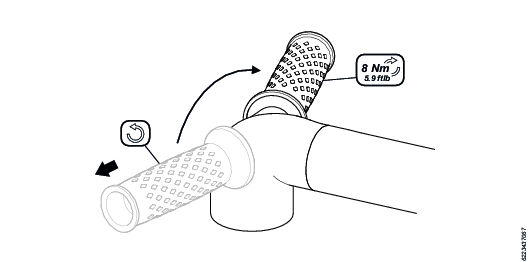
Clean the strainer at the air inlet frequently to prevent clogging and decreased capacity.
Installation
Installation Requirements
Air Quality
For optimum performance and maximum product life we recommend the use of compressed air with a maximum dew point of +10°C (50°F). We also recommend to install an Atlas Copco refrigeration type air dryer.
Use a separate air filter which removes solid particles larger than 30 microns and more than 90% of liquid water. Install the filter as close as possible to the product and prior to any other air preparation units to avoid pressure drop.
For impulse/impact tools make sure to use lubricators adjusted for these tools. Regular lubricators will add too much oil and therefore decrease the tool performance due to too much oil in the motor.
Make sure that the hose and couplings are clean and free from dust before connecting to the tool.
Both lubricated and lubrication free products will benefit from a small quantity of oil supplied from a lubricator.
Air Lubrication Guide
Brand | Air lubrication |
|---|---|
Atlas Copco | Optimizer (1 liter) 9090 0000 04 |
Q8 | Chopin 46 |
Shell | Shell Air Tool Oil S2 A 320 |
Compressed Air Connection
For correct air pressure and hose size, see the Technical Product Data on - https://servaid.atlascopco.com or www.atlascopco.com.
Make sure that the hose and couplings are clean and free from dust before connecting to the tool.
Installation Instructions
Visual Inspection - Tools and Accessories
Inspect the tool and its parts visually before use.
The parts in the list below may vary depending on model.
Wheel guard or Backing pad
Adapters, nuts or flange washers
Support handle
Throttle lever and security mechanism
Autobalancer
Spindle
Look for any damage, grease or oil leakage that can compromise the safety of the tool.
Visual Inspection - Air Installation
Inspect the air installation visually from the supply point to the tool before use.
Hose
Couplings
System pressure
Air filter
Look for any damage that can compromise the safety of the tool.
Operation
Ergonomic Guidelines
Consider your workstation as you read through this list of general ergonomic guidelines to identify areas for improvement in posture, component placement, or work environment.
Take frequent breaks and change work positions frequently.
Adapt the workstation area to your needs and the work task.
Adjust for a convenient reach range by determining where parts and tools need to be located to avoid static load.
Use workstation equipment such as tables and chairs appropriate for the work task.
Avoid work positions above shoulder level or with static holding during assembly operations.
When working above shoulder level, reduce the load on the static muscles by lowering the weight of the tool, using for example torque arms, hose reels or weight balancers. You can also reduce the load on the static muscles by holding the tool close to the body.
Take frequent breaks.
Avoid extreme arm or wrist postures, particularly during operations requiring a degree of force.
Adjust for a convenient field of vision that requires minimal eye and head movements.
Use appropriate lighting for the work task.
Select the appropriate tool for the work task.
In noisy environments, use ear protection equipment.
Use high-quality inserted tools and consumables to minimize exposure to excessive levels of vibration.
Minimize exposure to reaction forces.
When cutting:
A cut-off wheel can get stuck if the cut-off wheel is bent or not guided properly. Use the correct flange for the cut-off wheel and avoid bending the cut-off wheel during operation.
When drilling:
The drill might stall when the drill bit breaks through. Use support handles if the stall torque is high. The safety standard ISO11148 part 3 recommends using a device to absorb a reaction torque above 10 Nm for pistol grip tools and 4 Nm for straight tools.
When using direct-driven screwdrivers or nutrunners:
Reaction forces depend on the tool settings and joint characteristics. Strength and posture determine the amount of reaction force that an operator can tolerate. Adapt the torque setting to the operator's strength and posture and use a torque arm or reaction bar if the torque is too high.
In dusty environments, use a dust extraction system or wear a mouth protection mask.
Configuration Instructions
Fitting of Support Handle
The support handle can be attached to any side of the tool:
Remove the support handle by turning it counterclockwise.
Attach the support handle to the opposite side.
Tighten the handle clockwise to the recommended torque.
Adjusting the Wheel Guard
Put the wheel guard in the wanted position between yourself and the grinding wheel.
Fasten the wheel guard and make sure it is safely attached.
Operating Instructions
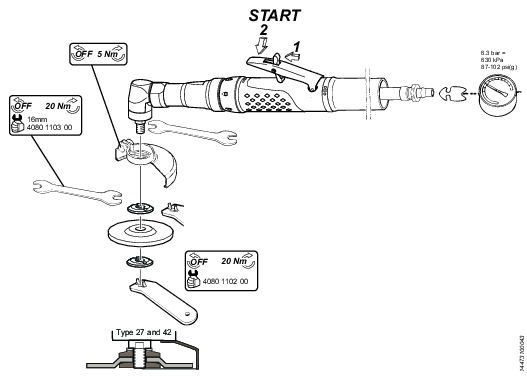
Mounting of Abrasive Equipment
Use only recommended sizes and types of abrasives.
Do not use mounting wheels that are chipped or cracked, or may have been dropped.
Correct mounting is necessary to prevent injury from broken mounted wheels.
Do not fit a wheel soaked in any fluid.
Grinding wheels should be a free fit but not loose on the spindle to prevent stress at the hole. Do not use reducing bushes to fit large hole grinding wheels.
Attach wheel with flanges conforming to international standard and in good condition.
Flanges shall be clean, have a flat contact surface and be without cracks and burrs.
Do not use unauthorised bushings or adaptors to attach large hole abrasive wheels.
Use blotters when delivered with the grinding wheel.
Do not mismatch wheel- and spindle thread.
Spindle and spindle threads shall be without damage or wear.
Mount the wheel correctly and tighten to recommended torque to prevent that the wheel falls off when the air grinder is stopped.
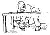
Do a test run of every new mounted wheel in a safe position for 30 seconds. Use a barrier such as under a heavy work table to stop any possible broken wheel parts. Stop immediately if vibration is excessive
Setting-up Instructions
Testing of the tool should only be done by professional technicians. The technicians must be authorized to test this type of tool and to operate a pneumatic system in accordance with national directives.
Do a free speed check of the tool every day and whenever the tool has been serviced. Do the free speed check with the grinding equipment removed.
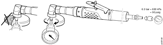
Use a pressure regulator to prevent a too high air pressure which can cause overspeed.
Make sure that connections and the air hose are in good condition.
Service
Maintenance Instructions
General Service and Maintenance Safety
Do not dismantle the tool.
The service must only be done by authorized workshops or qualified service technicians.
Service Recommendations
Preventive maintenance is recommended at regular intervals. See the detailed information on preventive maintenance. If the product is not working properly, take it out of service and inspect it.
If no detailed information about preventive maintenance is included, follow these general guidelines:
Clean appropriate parts accurately
Replace any defective or worn parts
Overhaul and Maintenance
Perform an overhaul of the tool at six-months intervals. Inspect and maintain the tool more often if it is in heavy duty service or not running correctly.
Clean the motor parts and apply a thin layer of air lubrication oil onto the vanes and inner surface of cylinder and end plates.
Assemble the motor and make sure that it is running free. Add two drops of oil through the air inlet and run the motor at idling speed for 5-10 seconds.
Change the grease in the angle gear after approximately 200 hours of operation. See Lubrication.
Inspect the sealing lip and adjacent column for wear. The seal is essential to keep lubricant in the gear box.
Clean the strainer at the air inlet frequently to prevent clogging and decreased capacity.
Replacement of Vanes
Replace the vanes in the motor when a power drop of the tool is experienced. If the vanes are not replaced in time other motor parts may be damaged. For increased life length of the vanes use an oil lubricator to dose oil into the air inlet.
Lubrication Instructions
Rust Protection and Cleaning
Water in the compressed air can cause rust. To prevent rust we strongly recommend to install an air dryer.
Water and particles can cause sticking of vanes and valves. This can be prevented by installing an air filter close to the product to avoid pressure drop.
Before longer standstills always protect your tool by adding a few drops of oil into the air inlet. Run the tool for 5–10 seconds and absorb any access oil at the air outlet in a cloth.
Lubrication
For longer service life of the bevel gear, Inject 1 gram of lubricant with the grease gun (4150 1982 20) every 8 operating hours.
Lubrication Guide
Use lubricants of good quality. The oils and greases listed in the lubrication table are examples of lubricants that can be recommended.
Brand | General purpose Bearings |
|---|---|
BP | Energrease LS-EP2 |
Castrol | Spheerol EP L2 |
Esso | Beacon EP2 |
Q8 | Rembrandt EP2 |
Mobil | Mobilegrease XHP 222 |
Shell | Alvania EP2 |
Texaco | Multifak EP2 |
Molycote | BR2 Plus |
Lubrication Angle Gears
Grease for angle gears | |
|---|---|
Rhenus | LKR03 |
Dismantling/Assembling Instructions
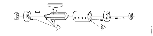
Instructions for Vane Motors
Dismantling
Service tools are also included in the Basic Service Tools set. For further information see ordering No. 9835 5485 00
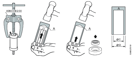
Dismantling tool Mandrel A
Ordering No. | Ø D | Ø C |
|---|---|---|
4080 0182 01 | 7 | 3.5 |
4080 0182 02 | 8 | 4.5 |
4080 0182 03 | 9 | 5.5 |
4080 0182 04 | 10 | 6.5 |
4080 0182 05 | 13 | 8.5 |
4080 0182 06 | 16 | 10.5 |
4080 0182 07 | 19 | 12.5 |
4080 0182 08 | 22 | 15.5 |
4080 0182 09 | 24 | 17.5 |
4080 0182 10 | 26 | 20.5 |
4080 0182 11 | 30 | 25.5 |
4080 0182 12 | 35 | 30.5 |
4080 0182 13 | 40 | 35.5 |
4080 0182 14 | 47 | 40.5 |
Inspection of Motor Parts
Assembling - According to Bäckströms Method
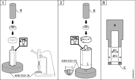
Service tools are also included in the Basic Service Tools set. For further information see ordering No. 9835 5485 00
Dismantling tool Mandrel B
Ordering No. | Ø D | Ø C |
|---|---|---|
4080 0567 04 | 12.5 | 5.2 |
4080 0567 11 | 14.5 | 6.5 |
4080 0567 01 | 15.5 | 5.2 |
4080 0567 05 | 18.5 | 6.2 |
4080 0567 02 | 18.5 | 8.2 |
4080 0567 06 | 21.5 | 7.5 |
4080 0567 03 | 21.5 | 8.2 |
4080 0567 07 | 25.5 | 10.5 |
4080 0567 08 | 27.5 | 12.5 |
4080 0567 09 | 31.5 | 15.5 |
4080 0567 10 | 34.5 | 18.5 |
Free Speed
Model | Max r/min |
|---|---|
LSV29 ST13-100E | 13000 |
Operating Instructions
Recycling
Environmental Regulations
When a product has served its purpose it has to be recycled properly. Dismantle the product and recycle the components in accordance with local legislation.
Batteries shall be taken care of by your national battery recovery organization.
Recycling Information
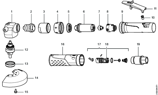
Position | Part | Recycle as |
|---|---|---|
1 | Angle head | Metal, Aluminum |
2 | Pinion set | Metal, Steel |
3 | Planetary gear complete | Metal, Steel |
4 | Front nut | Metal, Steel |
5 | Ring | Metal, Steel |
6 | Vane motor | Metal, Steel* |
7 | Governor | Metal, Steel |
8 | Governor housing | Metal, Aluminum |
9 | Motor casing | Metal, Aluminum |
10 | Bushing | Metal, Steel |
11 | Lever | Metal, Steel |
12 | Spindle complete | Metal, Steel |
13 | Screw ring | Metal, Steel |
14 | Wheel guard | Metal, Steel |
15 | Screws | Metal, Steel |
16 | Insulation sleeve | Plastics, Other, TPU |
17 | Valve complete (except nozzle) | Metal, Steel |
18 | Nozzle | Plastics, Other, POM |
19 | Adapter | Metal, Steel |
*The rotor blades (vanes) in the product contains PTFE, the normal health and safety recommendations concerning PTFE must be observed.