Power Focus S
Data collector
Product Information
General Information
Safety Signal Words
The safety signal words Danger, Warning, Caution, and Notice have the following meanings:
DANGER | DANGER indicates a hazardous situation which, if not avoided, will result in death or serious injury. |
WARNING | WARNING indicates a hazardous situation which, if not avoided, could result in death or serious injury. |
CAUTION | CAUTION, used with the safety alert symbol, indicates a hazardous situation which, if not avoided, could result in minor or moderate injury. |
NOTICE | NOTICE is used to address practices not related to personal injury. |
Warranty
Product warranty will expire in 12+1 months after dispatch from Atlas Copco's Distribution Center.
Normal wear and tear on parts is not included within the warranty.
Normal wear and tear is that which requires a part change or other adjustment/overhaul during standard tool maintenance typical for that period (expressed in time, operation hours or otherwise).
The product warranty relies on the correct use, maintenance, and repair of the tool and its component parts.
Damage to parts that occurs as a result of inadequate maintenance or performed by parties other than Atlas Copco or their Certified Service Partners during the warranty period is not covered by the warranty.
To avoid damage or destruction of tool parts, service the tool according to the recommended maintenance schedules and follow the correct instructions.
Warranty repairs are performed only in Atlas Copco workshops or by Certified Service Partners.
Atlas Copco offers extended warranty and state-of-the-art preventive maintenance through its ToolCover contracts. For further information, contact your local Service representative.
For electrical motors:
Warranty will apply, only when the electric motor has not been opened.
Website
Information concerning our Products, Accessories, Spare Parts and Published Matters can be found on the Atlas Copco website.
Please visit: www.atlascopco.com.
ServAid
ServAid is a portal that is continuously updated and contains Technical Information, such as:
Regulatory and Safety Information
Technical Data
Installation, Operation and Service Instructions
Spare Parts Lists
Accessories
Dimensional Drawings
Please visit: https://servaid.atlascopco.com.
For further Technical Information, please contact your local Atlas Copco representative.
Safety Data Sheets MSDS/SDS
The Safety Data Sheets describe the chemical products sold by Atlas Copco.
Please consult the Atlas Copco website for more information www.atlascopco.com/sds.
Country of Origin
For the Country of Origin, please refer to the information on the product label.
Dimensional Drawings
Dimensional Drawings can be found either in the Dimensional Drawings Archive, or on ServAid.
Please visit: https://webbox.atlascopco.com/webbox/dimdrw or https://servaid.atlascopco.com.
Overview
Power Consumption
Power consumption depends on the speed and torque of the tool. High speed and torque increase power consumption.
Tool | Off mode [W] | Idle mode [W] | Active mode [W] |
|---|---|---|---|
SR21 | <0.5 | <16 | 1090 |
STR61 | <0.5 | <16 | 1190 |
ST31 | <0.5 | <16 | 1040 |
ST61 | <0.5 | <16 | 1190 |
ST81 | <0.5 | <16 | 1290 |
ST101 | <0.5 | <16 | 1490 |
The power consumption in idle mode has been measured without any controller accessories or tool accessories connected.
Technical Product Data
Technical Product Data can be found on either ServAid, or the Atlas Copco website.
Please visit: https://servaid.atlascopco.com or www.atlascopco.com.
Installation
Installation Requirements
Installation Checklist
The Power Focus S is a control and monitoring unit for electric assembly tools. A working system consists of the following:
the Power Focus S
a tool cable, available in different models and lengths
an electric tool.
Controller Overview

1 | Emergency stop connector |
2 | E-stop in |
3 | Fan connector |
4 | Ethernet: Service port |
5 | Remote start enable switch |
6 | Out 24 V |
7 | E-stop out |
8 | Ethernet: Port B |
9 | Ethernet: Factory port/Port A |
Installation Instructions
Installing the Controller
The controller must be positioned so that the power switch is easily accessible.
For maximum tool performance, make sure that the controller is installed so that free airflow is provided. This improves the cooling of the controller.
Attach the mounting plate to a wall or to a steel plate, using three M6 screws. If attaching to a wall, use the correct wall bracket (plug and screw). If attaching to a steel plate, make sure that the steel plate is at least 2 mm thick.
Attach the controller to the mounting plate by tilting the controller and guiding the top flange of the mounting plate into the slot on the back of the controller. Lower the controller to engage the locking mechanism.
Install the retainer strap between the wall and the cable cover.
Open the front of the controller.
Connect the power cable to the power connector.
Make sure that the RCBO (residual-current device) is switched on.
Close the front of the controller.
Connect the tool cable to its socket on the bottom part of the controller.
Connect the power cable to a power supply.
Turn the power switch on.
An optional, threaded grounding point is available on the lower backside of the controller. The grounding point accepts a M4 threaded screw. The additional grounding does not replace the grounding from the wall socket.
Functional Test of the Residual-Current Circuit Breaker with Overcurrent Protection (RCBO) Device
A certified electrician must perform the functional test of the residual-current circuit breaker with overcurrent protection (RCBO) device, according to the IEC 61557-6 standard.
In high-voltage countries with a mains voltage of 220-240 V, the functional test can be performed by pushing the yellow button on the RCBO device.
In low-voltage countries with a mains voltage of 110-120 V, the functional test must be performed using the phase and neutral in the two test openings above the RCBO device.
Configuring Remote Start for Single or Multiple Controllers
The switch for remote start is found on the connector board located behind the front panel.
Whenever enabling remote start you must, for safety reasons, implement an emergency stop solution.
When using portable hand-held or portable hand-guided tools (such as tools used with torque reaction devices or dual trigger), remote start must be disabled by setting the switch on the controller to OFF. This is done to make it impossible to override the safety function within the tools.
Cabling
EM Stop button cables
Single/Multiple controllers | Dimension | Maximum length |
|---|---|---|
Single | 0.7 mm2 cable | 400 meters |
Multiple | 1.5 mm2 cable | 50 meters |
I/O Cables
For connecting multiple controllers with I/O cables distributing the emergency stop signal, use the maximum length according to the following table:
AWG 22 cable | Maximum total length |
|---|---|
4 controllers | 200 meters |
5 controllers | 140 meters |
6 controllers | 100 meters |
8 controllers | 70 meters |
10 controllers | 50 meters |
Emergency Stop
The Power Focus S is equipped with an infrastructure needed to create an emergency stop function with redundant breaking according to EN ISO 13849-1 category 3 PL d. The emergency stop function must be used when using remote start functionality.
The emergency stop function can be used with a supply disconnecting device (such as an EM Stop button). When pressed, it interrupts the supply voltage to the controller drive.
The emergency stop function can be used with either a single controller or up to 10 controllers in a single emergency stop chain. In a multiple controller configuration the emergency stop signal is distributed from the first controller to all interconnected controllers using E-stop in and E-stop out. The last controller in the chain returns a feedback signal to indicate that all controllers have received the emergency stop signal. The Emergency stop status is shown.
For the emergency stop there is a 24V DC output through the emergency stop connector on the connector board.
Emergency Stop Button
The supply disconnecting device may serve as an emergency stop when it is readily accessible to the operator and it is of the type described in EN 60204-1:2006, 5.3.2 a), b), c) or d). When intended for such use, the supply disconnecting device shall be colored red and have a yellow background. (Ref. EN 60204-1:2006, 10.7.5).
EM Stop Connector Configurations
The following EM Stop connector configurations are possible:
EM Stop default configuration (no EM Stop connected).
EM Stop entry configuration - single controller with hand-held tools.
EM Stop entry configuration - multiple controllers with hand-held tools.
EM Stop entry configuration - single controller with fixtured tools.
EM Stop entry configuration - multiple controllers with fixtured tools.
EM Stop entry configuration - single controller without manual reset.
EM Stop bypass configuration.
EM Stop loopback configuration.
EM Stop Default Configuration
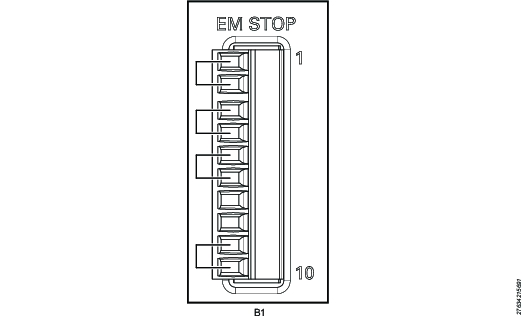
The Power Focus S comes with preinstalled jumpers for this configuration.
Use the following pin configuration:
Pin | Pin name | Use |
|---|---|---|
1 | EM_NC1 | Connect a jumper between pin 1 and pin 2 |
2 | EM_STOP+ | See pin 1 |
3 | EM_STOP+ | Connect a jumper between pin 3 and pin 4 |
4 | 24V_ISOL_EXT | See pin 3 |
5 | EM_STOP- | Connect a jumper between pin 5 and pin 6 |
6 | GND | See pin 5 |
7 | EM_BYPASS_STOP- | Do not use |
8 | EM_BYPASS_NC | Do not use |
9 | EM_RESET_IN | Connect a jumper between pin 9 and pin 10 |
10 | EM_NC2 | See pin 9 |
EM Stop Entry Configuration - Single Controller with Hand-held Tools
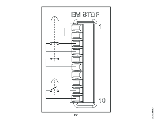
EM Stop button connector: Phoenix, 10-pin headers, 3.5 mm pitch
Use the following pin configuration:
Pin | Pin name | Use |
|---|---|---|
1 | EM_NC1 | Connect a jumper between pin 1 and pin 2 |
2 | EM_STOP+ | See pin 1 |
3 | EM_STOP+ | Connect an emergency button between pin 3 and pin 4 |
4 | 24V_ISOL_EXT | See pin 3 |
5 | EM_STOP- | Connect an emergency button between pin 5 and pin 6 |
6 | GND | See pin 5 |
7 | EM_BYPASS_STOP- | Do not use |
8 | EM_BYPASS_NC | Do not use |
9 | EM_RESET_IN | Connect a reset button between pin 9 and 10 |
10 | EM_NC2 | See pin 9 |
EM Stop Entry Configuration - Multiple Controllers with Hand-held Tools
Pin | Pin name | Use |
|---|---|---|
1 | EM_NC1 | Connect a jumper between pin 1 and pin 2 |
2 | EM_STOP+ | See pin 1 |
3 | EM_STOP+ | Connect an emergency button between pin 3 and pin 4 |
4 | 24V_ISOL_EXT | See pin 3 |
5 | EM_STOP- | Connect an emergency button between pin 5 and pin 6 |
6 | GND | See pin 5 |
7 | EM_BYPASS_STOP- | Do not use |
8 | EM_BYPASS_NC | Connect a reset button between pin 8 and 9 |
9 | EM_RESET_IN | See pin 8 |
10 | EM_NC2 | Do not use |
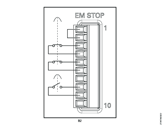
EM Stop Entry Configuration - Single Controller with Fixtured Tools
For this configuration, the remote start enable switch must be set to ON.
Pin | Pin name | Use |
|---|---|---|
1 | EM_NC1 | Connect a jumper between pin 1 and pin 2 |
2 | EM_STOP+ | See pin 1 |
3 | EM_STOP+ | Connect an emergency button between pin 3 and pin 4 |
4 | 24V_ISOL_EXT | See pin 3 |
5 | EM_STOP- | Connect an emergency button between pin 5 and pin 6 |
6 | GND | See pin 5 |
7 | EM_BYPASS_STOP- | Do not use |
8 | EM_BYPASS_NC | Do not use |
9 | EM_RESET_IN | Connect a reset button between pin 9 and 10 |
10 | EM_NC2 | See pin 9 |
EM Stop Entry Configuration - Multiple Controllers with Fixtured Tools
For this configuration, the remote start enable switch must be set to ON.
Pin | Pin name | Use |
|---|---|---|
1 | EM_NC1 | Connect a jumper between pin 1 and pin 2 |
2 | EM_STOP+ | See pin 1 |
3 | EM_STOP+ | Connect an emergency button between pin 3 and pin 4 |
4 | 24V_ISOL_EXT | See pin 3 |
5 | EM_STOP- | Connect an emergency button between pin 5 and pin 6 |
6 | GND | See pin 5 |
7 | EM_BYPASS_STOP- | Do not use |
8 | EM_BYPASS_NC | Connect a reset button between pin 8 and 9 |
9 | EM_RESET_IN | See pin 8 |
10 | EM_NC2 | Do not use |
EM Stop Entry Configuration - Single Controller without Manual Reset
EM Stop button connector: Phoenix, 10-pin headers, 3.5 mm pitch
Use the following pin configuration:
Pin | Pin name | Use |
|---|---|---|
1 | EM_NC1 | Do not use |
2 | EM_STOP+ | Do not use |
3 | EM_STOP+ | Connect an emergency button between pin 3 and pin 4 |
4 | 24V_ISOL_EXT | See pin 3 |
5 | EM_STOP- | Connect an emergency button between pin 5 and pin 6 |
6 | GND | See pin 5 |
7 | EM_BYPASS_STOP- | Do not use |
8 | EM_BYPASS_NC | Do not use |
9 | EM_RESET_IN | Connect a jumper between pin 9 and pin 10 |
10 | EM_NC2 | See pin 9 |
EM Stop Bypass Configuration
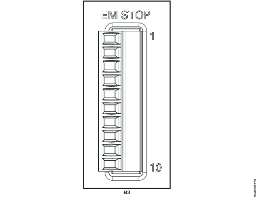
EM Stop I/O cable connector: Phoenix, 10-pin
Remove plug or use the following pin configuration:
Pin | Pin name | Use |
|---|---|---|
1 | EM_NC1 | Do not use |
2 | EM_STOP+ | Do not use |
3 | EM_STOP+ | Do not use |
4 | 24V_ISOL_EXT | Do not use |
5 | EM_STOP- | Do not use |
6 | GND | Do not use |
7 | EM_BYPASS_STOP- | Do not use |
8 | EM_BYPASS_NC | Do not use |
9 | EM_RESET_IN | Do not use |
10 | EM_NC2 | Do not use |
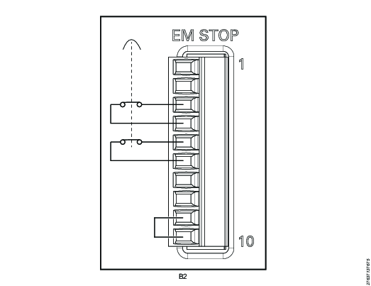
EM Stop loopback configuration
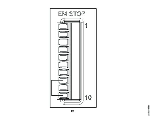
EM Stop I/O cable connector: Phoenix, 10-pin
Use the following pin configuration:
Pin | Pin name | Use |
|---|---|---|
1 | EM_NC1 | Do not use |
2 | EM_STOP+ | Do not use |
3 | EM_STOP+ | Do not use |
4 | 24V_ISOL_EXT | Do not use |
5 | EM_STOP- | Do not use |
6 | GND | Do not use |
7 | EM_BYPASS_STOP- | Do not use |
8 | EM_BYPASS_NC | Connect a jumper between pin 8 and pin 10 |
9 | EM_RESET_IN | Do not use |
10 | EM_NC2 | See pin 8 |
EM Stop Connection Scenarios
The following connection scenarios are possible:
Scenario 1 - No EM Stop, single controller with its remote start enable switch set to OFF.
Scenario 2 - EM Stop, single controller with its remote start enable switch set to ON and used with fixtured tools.
Scenario 3 - EM Stop, single controller with its remote start enable switch set to OFF and used with hand-held tools.
Scenario 4 - EM Stop, multiple controllers with their remote start enable switches set to OFF and using a reset button.
Scenario 5 - EM Stop, multiple controllers with their remote start enable switches set to OFF and using software reset.
Scenario 1 - No EM Stop, one controller with its remote start enable switch set to OFF

A | Controller |
B1 | EM Stop default configuration |
C | Remote start enable switch set to OFF |
In this scenario, no EM Stop is used. The corded tools tool trigger acts as the safety device. The remote start enable switch on the connector board is set to OFF. The EM Stop connector requires the default or no EM Stop configuration. This is the EM Stop connector configuration that the controller is shipped with.
Scenario 2 - EM Stop, single controller with its remote start enable switch set to ON

A | Controller |
B2 | EM Stop entry configuration |
C | Remote start enable switch set to ON |
D | EM Stop button cable connected to EM Stop connector |
E | EM Stop button |
In this scenario, an EM Stop is used with a single controller. The remote start enable switch on the connector board is set to ON. The EM Stop connector requires the B2 EM Stop entry configuration.
Scenario 3 - EM Stop, single controller with its remote start enable switch set to OFF and used with hand-held tools

A | Controller |
B2 | EM Stop entry configuration |
C | Remote start enable switch set to OFF |
D | EM Stop button cable connected to EM Stop connector |
E | EM Stop button |
In this scenario, an EM Stop is used with a single controller. The remote start enable switch on the connector board is set to OFF. The EM Stop connector requires the B2 EM Stop entry configuration.
Scenario 4 - EM Stop, multiple controllers with their remote start enable switches set to OFF and using a reset button

A1 | First controller |
A2 | Intermediate controller |
A3 | Last controller |
B2 | EM Stop entry configuration |
B3 | EM Stop bypass configuration |
B4 | EM Stop loopback configuration |
C | Remote start enable switch set to OFF |
D | EM Stop button cable connected to EM Stop connector |
E | EM Stop button |
F | I/O cables connected between E-STOP IN and E-STOP OUT |
G | Ethernet cables connected between PoE ports |
In this scenario, an EM Stop is used with multiple controllers that are interconnected with I/O cables and RJ45 Ethernet cables. The I/O cables are connected to the E-STOP IN and E-STOP OUT connectors as shown above. The RJ45 Ethernet cables are connected to the PoE ports (PoE 1, PoE 2). For each controller, the remote start enable switch on the connector board is set to OFF. The EM Stop connector configuration depends on the controller location within the chain:
For the first controller, the EM Stop connector requires the entry configuration.
For any intermediate controller, the EM Stop connector requires the bypass configuration.
For the last controller, the EM Stop connector requires the loopback configuration.
Scenario 5 - EM Stop, multiple controllers with their remote start enable switches set to OFF and using software reset

A1 | First controller |
A2 | Intermediate controller |
A3 | Last controller |
B2 | EM Stop entry configuration |
B3 | EM Stop bypass configuration |
B4 | EM Stop loopback configuration |
C | Remote start enable switch set to OFF |
D | EM Stop button cable connected to EM Stop connector |
E | EM Stop button |
F | I/O cables connected between E-STOP IN and E-STOP OUT |
G | Ethernet cables connected between PoE ports |
In this scenario, an EM Stop is used with multiple controllers that are interconnected with I/O cables and RJ45 Ethernet cables. The I/O cables are connected to the E-STOP IN and E-STOP OUT connectors as shown above. The RJ45 Ethernet cables are connected to the PoE ports (PoE 1, PoE 2). For each controller, the remote start enable switch on the connector board is set to OFF. The EM Stop connector configuration depends on the controller location within the chain:
For the first controller, the EM Stop connector requires the entry configuration.
For any intermediate controller, the EM Stop connector requires the bypass configuration.
For the last controller, the EM Stop connector requires the loopback configuration.
Operation
Ergonomic Guidelines
Consider your workstation as you read through this list of general ergonomic guidelines to identify areas for improvement in posture, component placement, or work environment.
Take frequent breaks and change work positions frequently.
Adapt the workstation area to your needs and the work task.
Adjust for a convenient reach range by determining where parts and tools need to be located to avoid static load.
Use workstation equipment such as tables and chairs appropriate for the work task.
Avoid work positions above shoulder level or with static holding during assembly operations.
When working above shoulder level, reduce the load on the static muscles by lowering the weight of the tool, using for example torque arms, hose reels or weight balancers. You can also reduce the load on the static muscles by holding the tool close to the body.
Take frequent breaks.
Avoid extreme arm or wrist postures, particularly during operations requiring a degree of force.
Adjust for a convenient field of vision that requires minimal eye and head movements.
Use appropriate lighting for the work task.
Select the appropriate tool for the work task.
In noisy environments, use ear protection equipment.
Use high-quality inserted tools and consumables to minimize exposure to excessive levels of vibration.
Minimize exposure to reaction forces.
When cutting:
A cut-off wheel can get stuck if the cut-off wheel is bent or not guided properly. Always use the correct flange for the cut-off wheel and avoid bending the cut-off wheel during operation.
When drilling:
The drill might stall when the drill bit breaks through. Use support handles if the stall torque is high. The safety standard ISO11148 part 3 recommends using a device to absorb a reaction torque above 10 Nm for pistol grip tools and 4 Nm for straight tools.
When using direct-driven screwdrivers or nutrunners:
Reaction forces depend on the tool settings and joint characteristics. Strength and posture determine the amount of reaction force that an operator can tolerate. Adapt the torque setting to the operator's strength and posture and use a torque arm or reaction bar if the torque is too high.
In dusty environments, use a dust extraction system or wear a mouth protection mask.
Operating Instructions
LED Status Light
The LEDs on the front of the Power Focus S shows the status of the controller. Some statuses are also shown as error codes on connected Power Focus 8 controllers.

1 | White LED |
2 | Red LED |
3 | Blue LED |
Several different LED statuses can be shown simultaneously
LED color | LED behavior | Power Focus S status | Power Focus 8 error code |
|---|---|---|---|
White | Solid | Power connected | |
Off | Power disconnected | ||
Red | Solid | Tool disconnected | 1011 |
Off | Tool connected | 1010 | |
Blinking | Emergency stop | 3040 | |
Blue | Solid | Drive connected | 3053 |
Off | Drive disconnected | 3054 | |
Blinking | Software update ongoing |
Service
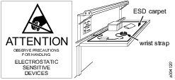
Preventing ESD Problems
The components inside the product and controller are sensitive to electrostatic discharge. To avoid future malfunction, make sure that service and maintenance is carried out in an ESD approved work environment. The figure below shows an example of an appropriate service work station.
Maintenance Instructions
Service Recommendations
Preventive maintenance is recommended at regular intervals. See the detailed information on preventive maintenance. If the product is not working properly, take it out of service and inspect it.
If no detailed information about preventive maintenance is included, follow these general guidelines:
Replace any defective or worn parts
Replacing the Backup Battery for the Clock and Calendar Function
For the clock and calendar function, the controller uses a backup battery. The 3 V lithium backup battery is of the CR2032 type.
To replace the backup battery, do the following:
Unplug the Power Focus S mains connector.
Open the side of the controller.
Remove the old battery and replace it with a new battery of the same type.
Close the side.
Repair Instructions
Wiring
If the plug on the power cable needs to be replaced, use the following wiring guide:
Color | Input |
|---|---|
Brown or black | Live |
Blue | Neutral |
Green and yellow | Protective ground |
Recycling
Environmental Regulations
When a product has served its purpose it has to be recycled properly. Dismantle the product and recycle the components in accordance with local legislation.
Batteries shall be taken care of by your national battery recovery organization.
Recycling Information

Position | Part | Recycle as |
|---|---|---|
1 | Chassis | Aluminum |
2 | Rubber feet | Rubber |
3 | Screw | Steel |
4 | Wall mount | Steel |
5 | Screw | Steel |
6 | Screw | Steel |
7 | Handle | Zinc |
8 | Connector board | WEEE |
9 | Cover | Plastic (ABS+CF) |
10 | Connector cover | Plastic (PC-ABS) |
11 | Strap | Plastic (PA) + Al or Cu terminal |
12 | Screw | Steel |
13 | Front panel inner | Plastic (PC-ABS) |
14 | Front panel | Plastic (PC-ABS) |
15 | Light guide | Plastic (PC) |
16 | Front holder | Steel |
17 | Screw | Steel |
18 | Bracket | Aluminum-zinc |
19 | Screw | Steel |
20 | Main switch | WEEE |
21 | Cable harness | WEEE |
22 | Screw | Steel |
23 | Cable cover | Steel |
24 | Screw | Steel |
25 | Cable harness | WEEE |
26 | Base board | WEEE |
27 | Screw | Steel |
28 | Label | Plastic (PVC) |
29 | Spacing screw | Steel |
30 | Shield plate | Aluminum-zinc |
31 | TPLC board | WEEE |
32 | Screw | Steel |
33 | Chassis lid | Aluminum |
34 | Washer | Steel |
35 | Screw | Steel |
36 | Thermal pad | Silicone rubber or Fiberglass |
37 | Terminal holder | Plastic (PA) |
38 | Aux board | WEEE |
39 | Protection sheet | Plastic (PET) |
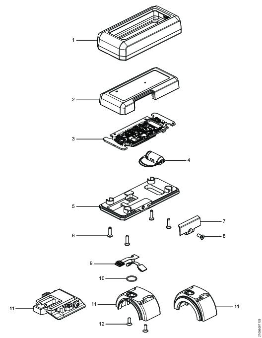
Recycling Information
Position | Part | Recycle as |
|---|---|---|
1 | Protective cover | Rubber, PU |
2 | Top cover | Plastic, Other, PA |
3 | PCBA assembly | Electronics |
4 | Capacitor assembly | Electronics |
5 | Bottom plate | Metals, Aluminum |
6 | Hex sock screw | Metals, Steel |
7 | Lid | Plastic, Other, PA |
8 | Hex sock screw | Metals, Steel |
9 | Flex board PCBA | Electronics |
10 | O-ring | Rubber, NBR |
11 | Scanner bracket | Metals, Aluminum |
12 | Hex sock screw | Metals, Steel |