Power Focus 6000
Control Unit
Product Information
General Information
Safety Signal Words
The safety signal words Danger, Warning, Caution, and Notice have the following meanings:
DANGER | DANGER indicates a hazardous situation which, if not avoided, will result in death or serious injury. |
WARNING | WARNING indicates a hazardous situation which, if not avoided, could result in death or serious injury. |
CAUTION | CAUTION, used with the safety alert symbol, indicates a hazardous situation which, if not avoided, could result in minor or moderate injury. |
NOTICE | NOTICE is used to address practices not related to personal injury. |
Warranty
Product warranty will expire 12+1 months after dispatch from Atlas Copco's Distribution Center.
Normal wear and tear on parts is not included within the warranty.
Normal wear and tear is that which requires a part change or other adjustment/overhaul during standard tools maintenance typical for that period (expressed in time, operation hours or otherwise).
The product warranty relies on the correct use, maintenance, and repair of the tool and its component parts.
Damage to parts that occurs as a result of inadequate maintenance or performed by parties other than Atlas Copco or their Certified Service Partners during the warranty period is not covered by the warranty.
To avoid damage or destruction of tool parts, service the tool according to the recommended maintenance schedules and follow the correct instructions.
Warranty repairs are only performed in Atlas Copco workshops or by Certified Service Partners.
Atlas Copco offers extended warranty and state of the art preventive maintenance through its ToolCover contracts. For further information contact your local Service representative.
For electrical motors:
Warranty will only apply when the electric motor has not been opened.
Website
Information concerning our Products, Accessories, Spare Parts and Published Matters can be found on the Atlas Copco website.
Please visit: www.atlascopco.com.
ServAid
ServAid is a portal that is continuously updated and contains Technical Information, such as:
Regulatory and Safety Information
Technical Data
Installation, Operation and Service Instructions
Spare Parts Lists
Accessories
Dimensional Drawings
Please visit: https://servaid.atlascopco.com.
For further Technical Information, please contact your local Atlas Copco representative.
Safety Data Sheets MSDS/SDS
The Safety Data Sheets describe the chemical products sold by Atlas Copco.
Please consult the Atlas Copco website for more information www.atlascopco.com/sds.
Country of Origin
For the Country of Origin, please refer to the information on the product label.
Dimensional Drawings
Dimensional Drawings can be found either in the Dimensional Drawings Archive, or on ServAid.
Please visit: http://webbox.atlascopco.com/webbox/dimdrw or https://servaid.atlascopco.com.
Overview
Normal Environmental Conditions
This product is designed to be safe under the following conditions:
Indoor use
Altitude up to 2 000 m
Operating temperature +5.0 °C / +41.0 °F to +50.0 °C / +122.0 °F
Storage temperature +5.0 °C / +41.0 °F to +50.0 °C / +122.0 °F
Maximum relative humidity 80 % for temperatures up to 31 °C / 89 °F decreasing linearly to 50 % relative humidity at 40 °C / 104 °F
Network Connections
Factory LAN - 100/100 Mb/s
Service LAN - 100/100 Mb/s
Technical Product Data
Technical Product Data can be found on either ServAid, or the Atlas Copco website.
Please visit: https://servaid.atlascopco.com or www.atlascopco.com.
Service Overview
Service Recommendations
Preventive maintenance is recommended at regular intervals. See the detailed information on preventive maintenance. If the product is not working properly, take it out of service and inspect it.
If no detailed information about preventive maintenance is included, follow these general guidelines:
Replace any defective or worn parts
Installation
Installation Requirements
Installation Checklist
The PF6000 IRC is a control and monitoring unit for battery assembly tools. A working system consists of the following:
the PF6000 IRC
an IAM, Intelligent Application Module, containing software applications, configurations, results, and events
a battery tool
Front Connections
Connections and switches behind the front cover of the Power Focus 6000 IRC controller:

Battery
Cable
USB port
IAM
Factory Ethernet port
Anybus CC
Installation Instructions
Installing the Controller
The controller must be positioned so that the power supply is easily accessible.
For maximum tool performance, make sure that the controller is installed so that free airflow is provided. This improves the cooling of the controller.
Attach the mounting plate to a wall or to a steel plate, using three M6 screws. If attaching to a wall, use the correct wall bracket (plug and screw). If attaching to a steel plate, make sure that the steel plate is at least 2 mm thick.
Attach the controller to the mounting plate by tilting the controller and guiding the top flange of the mounting plate into the slot on the back of the controller. Lower the controller to engage the locking mechanism.
Install the retainer strap between the wall and the cable cover.
Open the front access door of the controller.
Place the IAM in its socket on the back of the front access door.
Close the front access door.
Connect power to the 24V inlet to turn the controller on.
An optional, threaded grounding point is available on the lower backside of the controller. The grounding point accepts a M4 threaded screw.
Operation
Ergonomic Guidelines
Consider your workstation as you read through this list of general ergonomic guidelines to identify areas for improvement in posture, component placement, or work environment.
Take frequent breaks and change work positions frequently.
Adapt the workstation area to your needs and the work task.
Adjust for a convenient reach range by determining where parts and tools need to be located to avoid static load.
Use workstation equipment such as tables and chairs appropriate for the work task.
Avoid work positions above shoulder level or with static holding during assembly operations.
When working above shoulder level, reduce the load on the static muscles by lowering the weight of the tool, using for example torque arms, hose reels or weight balancers. You can also reduce the load on the static muscles by holding the tool close to the body.
Take frequent breaks.
Avoid extreme arm or wrist postures, particularly during operations requiring a degree of force.
Adjust for a convenient field of vision that requires minimal eye and head movements.
Use appropriate lighting for the work task.
Select the appropriate tool for the work task.
In noisy environments, use ear protection equipment.
Use high-quality inserted tools and consumables to minimize exposure to excessive levels of vibration.
Minimize exposure to reaction forces.
When cutting:
A cut-off wheel can get stuck if the cut-off wheel is bent or not guided properly. Use the correct flange for the cut-off wheel and avoid bending the cut-off wheel during operation.
When drilling:
The drill might stall when the drill bit breaks through. Use support handles if the stall torque is high. The safety standard ISO11148 part 3 recommends using a device to absorb a reaction torque above 10 Nm for pistol grip tools and 4 Nm for straight tools.
When using direct-driven screwdrivers or nutrunners:
Reaction forces depend on the tool settings and joint characteristics. Strength and posture determine the amount of reaction force that an operator can tolerate. Adapt the torque setting to the operator's strength and posture and use a torque arm or reaction bar if the torque is too high.
In dusty environments, use a dust extraction system or wear a mouth protection mask.
Configuration Instructions
Programming a Pset
Please refer to the User guide for information on how to program a Pset.
Operating Instructions
Shutting down the Controller
Avoid using the controller while shutting it down to prevent data loss.
Disconnect the 24 V power supply to shutdown the controller.
Service
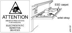
Preventing ESD Problems
The components inside the product and controller are sensitive to electrostatic discharge. To avoid future malfunction, make sure that service and maintenance is carried out in an ESD approved work environment. The figure below shows an example of an appropriate service work station.
Maintenance Instructions
Service Recommendations
Preventive maintenance is recommended at regular intervals. See the detailed information on preventive maintenance. If the product is not working properly, take it out of service and inspect it.
If no detailed information about preventive maintenance is included, follow these general guidelines:
Replace any defective or worn parts
Replacing the Backup Battery for the Clock and Calendar Function
For the clock and calendar function, the controller uses a backup battery. The 3 V lithium backup battery is of the CR2032 type.
To replace the backup battery, do the following:
Open the front access door of the controller.
On the rear of the front access door, loosen the screws of the battery cover and remove the battery cover.
Remove the old battery and replace it with a new battery of the same type.
Reinstall the battery cover and tighten the screws on the rear of the front access door.
Close the front access door.
Recycling
Environmental Regulations
When a product has served its purpose it has to be recycled properly. Dismantle the product and recycle the components in accordance with local legislation.
Batteries shall be taken care of by your national battery recovery organization.