Product Information
General Information
Safety Signal Words
The safety signal words Danger, Warning, Caution, and Notice have the following meanings:
DANGER | DANGER indicates a hazardous situation which, if not avoided, will result in death or serious injury. |
WARNING | WARNING indicates a hazardous situation which, if not avoided, could result in death or serious injury. |
CAUTION | CAUTION, used with the safety alert symbol, indicates a hazardous situation which, if not avoided, could result in minor or moderate injury. |
NOTICE | NOTICE is used to address practices not related to personal injury. |
Warranty
Product warranty will expire 12 months after the product is first taken into use, but will in any case expire at the latest 13 months after delivery.
Normal wear and tear on parts is not included within the warranty.
Normal wear and tear is that which requires a part change or other adjustment/overhaul during standard tools maintenance typical for that period (expressed in time, operation hours or otherwise).
The product warranty relies on the correct use, maintenance, and repair of the tool and its component parts.
Damage to parts that occurs as a result of inadequate maintenance or performed by parties other than Atlas Copco or their Certified Service Partners during the warranty period is not covered by the warranty.
To avoid damage or destruction of tool parts, service the tool according to the recommended maintenance schedules and follow the correct instructions.
Warranty repairs are only performed in Atlas Copco workshops or by Certified Service Partners.
Atlas Copco offers extended warranty and state of the art preventive maintenance through its ToolCover contracts. For further information contact your local Service representative.
For electrical motors:
Warranty will only apply when the electric motor has not been opened.
ServAid
ServAid is a portal that is continuously updated and contains Technical Information, such as:
Regulatory and Safety Information
Technical Data
Installation, Operation and Service Instructions
Spare Parts Lists
Accessories
Dimensional Drawings
Please visit: https://servaid.atlascopco.com.
For further Technical Information, please contact your local Atlas Copco representative.
Website
Information concerning our Products, Accessories, Spare Parts and Published Matters can be found on the Atlas Copco website.
Please visit: www.atlascopco.com.
Safety Data Sheets MSDS/SDS
The Safety Data Sheets describe the chemical products sold by Atlas Copco.
Please consult the Atlas Copco website for more information www.atlascopco.com/sds.
Country of Origin
For the Country of Origin, please refer to the information on the product label.
Dimensional Drawings
Dimensional Drawings can be found either in the Dimensional Drawings Archive, or on ServAid.
Please visit: http://webbox.atlascopco.com/webbox/dimdrw or https://servaid.atlascopco.com.
Overview
Design and Function
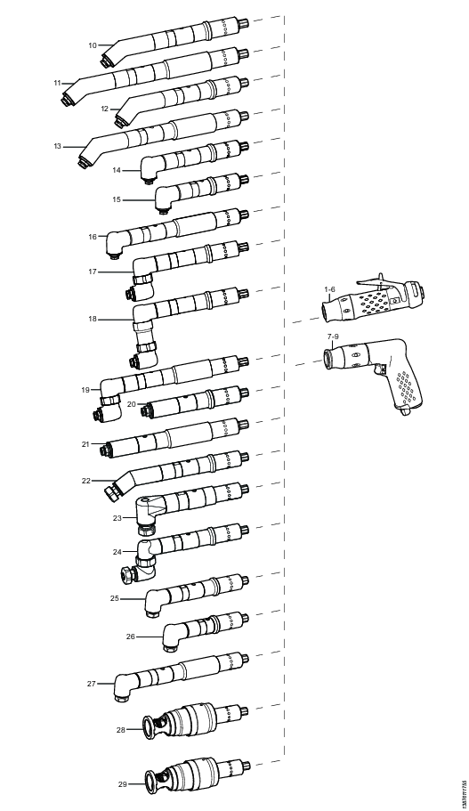
This high-quality handheld drill consists of two main parts; the motor unit and the drill head unit. The motor unit comes in various speeds to suit all kind of applications. The drill head unit is available in different angles. All motor units and drill head units are interchangeable with each other and ordered separately.
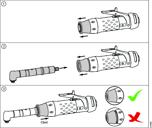
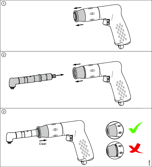
In order to assemble or disassemble the angle unit to the motor unit, pull the quick change mechanism forward to unlock it.
Product Range Overview for Modular Drills
Pos | Model | Specification | Nominal Tool speed a) | Ordering No. |
|---|---|---|---|---|
| Motor unit |
| Free speed without Drill head unit |
|
1 | LBD16M-005 |
| 500 r/min | 8421 0122 05 |
2 | LBD16M-010 |
| 1 000 r/min | 8421 0122 10 |
3 | LBD16M-018 |
| 1 800 r/min | 8421 0122 18 |
4 | LBD16M-032 |
| 3 600 r/min | 8421 0122 32 |
5 | LBD16M-045 |
| 5 100 r/min | 8421 0122 45 |
6 | LBD16M-055 |
| 6 200 r/min | 8421 0122 55 |
7 | LBP16M 010 |
| 1 000 r/min | 8421 0124 10 |
8 | LBP16M 033 |
| 3 300 r/min | 8421 0124 33 |
9 | LBP16M 060 |
| 6 000 r/min | 8421 0124 60 |
|
|
| ||
| Drill head unit |
| Ratio for Drill head unit |
|
10 | BHM30C-5-0 | Angle 30 degrees. Collet 3 mm. Capacity 5 mm. | 14:15 | 8421 0123 20 |
10 | BHM30T-1-4 | Angle 30 degrees. UNF 1/4”-28 | 14:15 | 8421 0123 21 |
11 | BHM30EC-5-0 | Angle 30 degrees. Collet 3 mm. Capacity 5 mm. | 14:15 | 8421 0123 28 |
11 | BHM30ET-1-4 | Angle 30 degrees. UNF 1/4”-28 | 14:15 | 8421 0123 29 |
12 | BHM45C-5-0 | Angle 45 degrees. Collet 3 mm. Capacity 5 mm. | 14:15 | 8421 0123 10 |
12 | BHM45T-1-4 | Angle 45 degrees. UNF 1/4”-28 | 14:15 | 8421 0123 11 |
13 | BHM45EC-5-0 | Angle 45 degrees. Collet 3 mm. Capacity 5 mm. | 14:15 | 8421 0123 18 |
13 | BHM45ET-1-4 | Angle 45 degrees. UNF 1/4”-28 | 14:15 | 8421 0123 19 |
14 | BHM90C-5-0 | Angle 90 degrees. Collet 3 mm. Capacity 5 mm. | 14:16 | 8421 0123 00 |
14 | BHM90C-6-6 | Angle 90 degrees. Collet 6 mm. Capacity 6.6 mm. | 1:1 | 8421 0123 05 |
14 | BHM90T-1-4 | Angle 90 degrees. UNF 1/4”-28 | 14:16 | 8421 0123 01 |
14 | BHM90T-1-4 | Angle 90 degrees. UNF 1/4”-28 | 1:1 | 8421 0123 06 |
15 | BHM90SC-5-0 | Angle 90 degrees. Collet 3 mm. Capacity 5 mm | 14:16 | 8421 0123 02 |
16 | BHM90EC-5-0 | Angle 90 degrees. Collet 3 mm. Capacity 5 mm | 14:16 | 8421 0123 08 |
16 | BHM90ET-1-4 | Angle 90 degrees. UNF 1/4”-28 | 14:16 | 8421 0123 09 |
17 | BHM90ZC-5-0 | Angle 360 degrees. Collet 3 mm. Capacity 5 mm. | 14:16 (x 2) | 8421 0123 30 |
17 | BHM90ZT-1-4 | Angle 360 degrees. UNF 1/4”-28 | 14:16 (x 2) | 8421 0123 31 |
18 | BHM90XZC-5-0 | Angle 360 degrees. Collet 3 mm. Capacity 5 mm. | 14:16 (x 2) | 8421 0123 33 |
19 | BHM90EZC-5-0 | Angle 360 degrees. Collet 3 mm. Capacity 5 mm. | 14:16 (x 2) | 8421 0123 38 |
19 | BHM90EZT-1-4 | Angle 360 degrees. UNF 1/4”-28 | 14:16 (x 2) | 8421 0123 39 |
20 | BHM0C-5-0 | Short straight. Collet 3 mm. Capacity 5 mm. | 1:1 | 8421 0123 43 |
21 | BHM0T-1-4 | Short straight. UNF 1/4”-28 | 1:1 | 8421 0123 44 |
22 | BHM30C-6.6 | Angle 30 degrees. Collet 6.6 mm. Capacity 6.6 mm. | 14:15 | 8421 0123 15 |
23 | BHM90C-8.0 | Angle 90 degrees. Collet 8 mm. Capacity 8 mm. | 1:1 | 8421 0123 80 |
24 | BHM90ZC-6.6 | Angle 360 degrees. Collet 6.6 mm. Capacity 6.6 mm. | 14:16 (x 2) | 8421 0123 40 |
25 | BHM90C-5-0 MKII | Angle 90 degrees. Collet 3.3 mm. Capacity 5 mm. | 14:16 | 8421 0123 03 |
26 | BHM90SC-5-0 MKII | Angle 90 degrees. Collet 3.3 mm. Capacity 5 mm. | 14:16 | 8421 0123 04 |
27 | BHM90EC-5-0 MKII | Angle 90 degrees. Collet 3.3 mm. Capacity 5 mm. | 14:16 | 8421 0123 07 |
28 | BHM Microstop Cage | Short straight. UNF 1/4”-28. | 1:1 | 8421 0123 13 |
29 | Modular Countersink Cage | Short straight. M6x1. | 1:1 | 8421 0123 45 |
BHM = Drill head unit; M = Modular; C = Collet; E = Extended; S = Short; T = Thread; Z = Double angle; X = Extended Z a)The actual spindle speed for the complete tool is determined by the gear ratio of the selected drill head unit. Example: Selection of an LBP16M-033 motor unit (3 300 r/min) with a BHM90C-5-0 drill head unit (gear ratio 14:16) results in the free speed of: 3 300*(14/16) = 2 888 r/min. Gear ratio for Z shaped angle head units is multiplied two times: 3 300*(14/16)*(14/16) = 2 527 r/min free speed. |
Technical Product Data
Technical Product Data can be found on either ServAid, or the Atlas Copco website.
Please visit: https://servaid.atlascopco.com or www.atlascopco.com.
Service Overview
Service Recommendations
Preventive maintenance is recommended at regular intervals. See the detailed information on preventive maintenance. If the product is not working properly, take it out of service and inspect it.
If no detailed information about preventive maintenance is included, follow these general guidelines:
Clean appropriate parts accurately
Replace any defective or worn parts
Installation
Installation Requirements
Air Lubrication Guide
Brand | Air lubrication |
|---|---|
Atlas Copco | Optimizer (1 liter) 9090 0000 04 |
Q8 | Chopin 46 |
Shell | Shell Air Tool Oil S2 A 320 |
Installation Instructions
Mounting of Modular Drill Head Unit for LBD

Mounting of Modular Drill Head Unit for LBP
Operation
Ergonomic Guidelines
Consider your workstation as you read through this list of general ergonomic guidelines to identify areas for improvement in posture, component placement, or work environment.
Take frequent breaks and change work positions frequently.
Adapt the workstation area to your needs and the work task.
Adjust for a convenient reach range by determining where parts and tools need to be located to avoid static load.
Use workstation equipment such as tables and chairs appropriate for the work task.
Avoid work positions above shoulder level or with static holding during assembly operations.
When working above shoulder level, reduce the load on the static muscles by lowering the weight of the tool, using for example torque arms, hose reels or weight balancers. You can also reduce the load on the static muscles by holding the tool close to the body.
Take frequent breaks.
Avoid extreme arm or wrist postures, particularly during operations requiring a degree of force.
Adjust for a convenient field of vision that requires minimal eye and head movements.
Use appropriate lighting for the work task.
Select the appropriate tool for the work task.
In noisy environments, use ear protection equipment.
Use high-quality inserted tools and consumables to minimize exposure to excessive levels of vibration.
Minimize exposure to reaction forces.
When cutting:
A cut-off wheel can get stuck if the cut-off wheel is bent or not guided properly. Use the correct flange for the cut-off wheel and avoid bending the cut-off wheel during operation.
When drilling:
The drill might stall when the drill bit breaks through. Use support handles if the stall torque is high. The safety standard ISO11148 part 3 recommends using a device to absorb a reaction torque above 10 Nm for pistol grip tools and 4 Nm for straight tools.
When using direct-driven screwdrivers or nutrunners:
Reaction forces depend on the tool settings and joint characteristics. Strength and posture determine the amount of reaction force that an operator can tolerate. Adapt the torque setting to the operator's strength and posture and use a torque arm or reaction bar if the torque is too high.
In dusty environments, use a dust extraction system or wear a mouth protection mask.
Operating Instructions
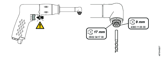
Exchanging the Drill Bit
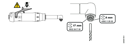
Exchanging the Drill Bit
Service
Maintenance Instructions
Service Recommendations
Preventive maintenance is recommended at regular intervals. See the detailed information on preventive maintenance. If the product is not working properly, take it out of service and inspect it.
If no detailed information about preventive maintenance is included, follow these general guidelines:
Clean appropriate parts accurately
Replace any defective or worn parts
Recycling
Environmental Regulations
When a product has served its purpose it has to be recycled properly. Dismantle the product and recycle the components in accordance with local legislation.
Batteries shall be taken care of by your national battery recovery organization.