EBP16-055F-P
Battery drill
Product Information
General Information
Safety Signal Words
The safety signal words Danger, Warning, Caution, and Notice have the following meanings:
DANGER | DANGER indicates a hazardous situation which, if not avoided, will result in death or serious injury. |
WARNING | WARNING indicates a hazardous situation which, if not avoided, could result in death or serious injury. |
CAUTION | CAUTION, used with the safety alert symbol, indicates a hazardous situation which, if not avoided, could result in minor or moderate injury. |
NOTICE | NOTICE is used to address practices not related to personal injury. |
Warranty
Product warranty will expire 12+1 months after dispatch from Atlas Copco's Distribution Center.
Normal wear and tear on parts is not included within the warranty.
Normal wear and tear is that which requires a part change or other adjustment/overhaul during standard tools maintenance typical for that period (expressed in time, operation hours or otherwise).
The product warranty relies on the correct use, maintenance, and repair of the tool and its component parts.
Damage to parts that occurs as a result of inadequate maintenance or performed by parties other than Atlas Copco or their Certified Service Partners during the warranty period is not covered by the warranty.
To avoid damage or destruction of tool parts, service the tool according to the recommended maintenance schedules and follow the correct instructions.
Warranty repairs are only performed in Atlas Copco workshops or by Certified Service Partners.
Atlas Copco offers extended warranty and state of the art preventive maintenance through its ToolCover contracts. For further information contact your local Service representative.
For electrical motors:
Warranty will only apply when the electric motor has not been opened.
Website
Information concerning our Products, Accessories, Spare Parts and Published Matters can be found on the Atlas Copco website.
Please visit: www.atlascopco.com.
ServAid
ServAid is a portal that is continuously updated and contains Technical Information, such as:
Regulatory and Safety Information
Technical Data
Installation, Operation and Service Instructions
Spare Parts Lists
Accessories
Dimensional Drawings
Please visit: https://servaid.atlascopco.com.
For further Technical Information, please contact your local Atlas Copco representative.
Safety Data Sheets MSDS/SDS
The Safety Data Sheets describe the chemical products sold by Atlas Copco.
Please consult the Atlas Copco website for more information www.atlascopco.com/sds.
Country of Origin
For the Country of Origin, please refer to the information on the product label.
Dimensional Drawings
Dimensional Drawings can be found either in the Dimensional Drawings Archive, or on ServAid.
Please visit: http://webbox.atlascopco.com/webbox/dimdrw or https://servaid.atlascopco.com.
Overview
System Functionality
Not available for all models.
The ToolsTalk Service 2 PC software package, is used for updating and storing software data and downloading configuration parameters to the tool. The tool is able to store and use several number of drill programs. All features in ToolsTalk Service 2 may not be available for this tool.
For more information, see ToolsTalk Service 2 User Edition user guide.
Tool Functionality
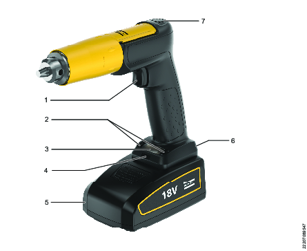
1 | Trigger |
2 | Function buttons |
3 | Display (HMI) |
4 | Front LED light |
5 | Battery |
6 | USB Port |
7 | Fan air outlet |
The tool is equipped with a display and a front LED light. Configured tool programs are stored in the tool and features can be selected for usage.
Display (HMI)
Note that depending on the model, some features and functions are not available on the tool.
Main Display
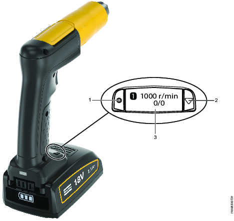
1 | Button - LEFT1 |
2 | Button - RIGHT1 |
3 | Display (HMI) |
1The position of the right or left button is based on the user holding the handle and pointing the drill away from their body.
Display at Startup

The user can switch between the cutter usage and the name by pressing the right hand button.

1A | Index of program listed and stored |
1B | Index of active program selected |
2 | Revolutions per minute |
3 | Cutter usage accumulated |
4 | Cutter usage limited |
5 | Name of the drill program |
Display Icons
Icon | Description |
|---|---|
| Battery warning |
| Temperature warning |
| Warning |
| Revolutions per minute |
| Wi-Fi Zone Tethering 1 |
| Service |
 | Forward direction |
 | Reverse direction |
| Unlock |
| LED light ON |
| LED light OFF |
| OK - apply function |
| NOK - cancel function |
| Bin |
| Cutter usage |
1Not available for all models.
Technical Product Data
Technical Product Data can be found on either ServAid, or the Atlas Copco website.
Please visit: https://servaid.atlascopco.com or www.atlascopco.com.
Installation
Installation Requirements
Attaching and Removing the Battery Pack
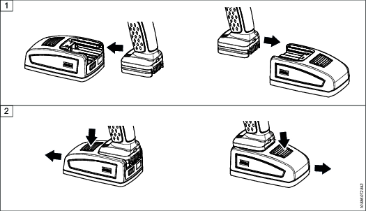
Attach the battery to the tool and make sure that it is fastened correctly. The battery can be attached pointing forward or backward to get the best accessibility and balance.
To remove the battery, press the button on the battery and push it out.
Tool Upgrade
A tool upgrade can be performed by an Atlas Copco Industrial Technique AB Service technician.
Contact your Atlas Copco Industrial Technique AB representative for support and more information.
Installation Instructions
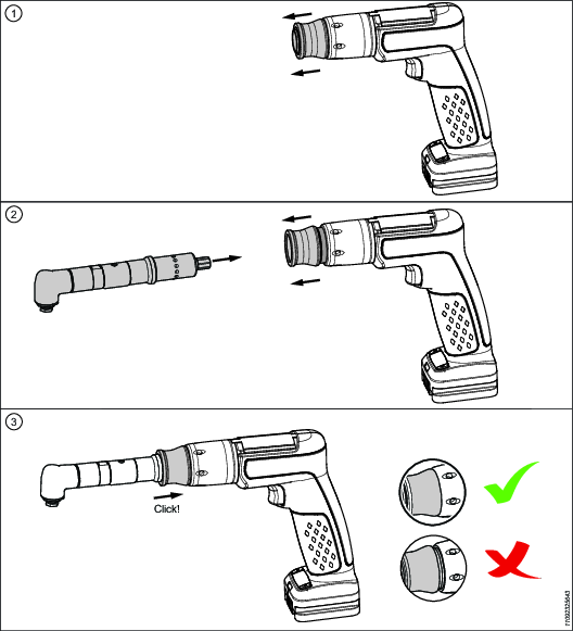
Mounting of Modular Drill Head Unit
Always disconnect the battery pack from the tool, before mounting a modular head unit to the tool.
Software Installation
For installation guidelines, see ToolsTalk Service 2 User Edition user guide.
Operation
Ergonomic Guidelines
Consider your workstation as you read through this list of general ergonomic guidelines to identify areas for improvement in posture, component placement, or work environment.
Take frequent breaks and change work positions frequently.
Adapt the workstation area to your needs and the work task.
Adjust for a convenient reach range by determining where parts and tools need to be located to avoid static load.
Use workstation equipment such as tables and chairs appropriate for the work task.
Avoid work positions above shoulder level or with static holding during assembly operations.
When working above shoulder level, reduce the load on the static muscles by lowering the weight of the tool, using for example torque arms, hose reels or weight balancers. You can also reduce the load on the static muscles by holding the tool close to the body.
Take frequent breaks.
Avoid extreme arm or wrist postures, particularly during operations requiring a degree of force.
Adjust for a convenient field of vision that requires minimal eye and head movements.
Use appropriate lighting for the work task.
Select the appropriate tool for the work task.
In noisy environments, use ear protection equipment.
Use high-quality inserted tools and consumables to minimize exposure to excessive levels of vibration.
Minimize exposure to reaction forces.
When cutting:
A cut-off wheel can get stuck if the cut-off wheel is bent or not guided properly. Use the correct flange for the cut-off wheel and avoid bending the cut-off wheel during operation.
When drilling:
The drill might stall when the drill bit breaks through. Use support handles if the stall torque is high. The safety standard ISO11148 part 3 recommends using a device to absorb a reaction torque above 10 Nm for pistol grip tools and 4 Nm for straight tools.
When using direct-driven screwdrivers or nutrunners:
Reaction forces depend on the tool settings and joint characteristics. Strength and posture determine the amount of reaction force that an operator can tolerate. Adapt the torque setting to the operator's strength and posture and use a torque arm or reaction bar if the torque is too high.
In dusty environments, use a dust extraction system or wear a mouth protection mask.
Operating Instructions
Wi-Fi Zone Tethering
Not available for all models.
This tool features the Wi-Fi Zone Tethering (WZT) function, intended to make the tool less susceptible to theft.
The functionality limits the usability of the tool when it exceeds a specific Wi-Fi network or tethering zone. The tool has to be tethered to a network and can only be used for a limited time without being connected to the network, before the tool is locked. When the tool is locked it cannot be used for drilling. The tool's display will show the tool event.
When the tool is reconnected to the network again the tool is unlocked and fully operational again.
For more information to configure the Wi-Fi Tethering, see ToolsTalk Service 2 User Edition user guide.
Internal Cooling

Operating the Tool
Menu Navigation Flow
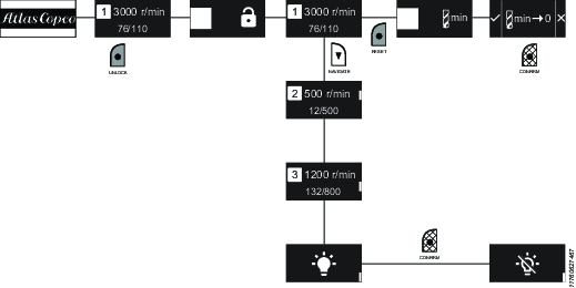
Menu Navigation Buttons
Button | Action |
|---|---|
| Press RIGHT button to navigate. |
| Press LEFT button and hold down for approximately 2 seconds. |
| Press LEFT button to select. |
Key Lock
On start up the display lock is active.
Unlock the Key Lock
Press and hold down the left hand button for approximately 2 seconds.
Once unlocked the operator can enter and navigate the menu.
Activate the Key Lock
Press the tool trigger.
OR
Do not press the button or trigger for a short while.
Operating the Drill
Press the trigger.
The selected drill program on the display will be used when the trigger is pressed.
The tool will carry out status checks before drilling can be carried out:
Temperature
Battery voltage
Internal voltage
The tool will start if all is OK.
The tool will not start the drill program if there are any discrepancies. The display will show the tool event.
Drill a hole.
While drilling, the position of the trigger is continuously used to determine the desired speed of the motor.
The tool monitors the time that the drill program has been running in order to impose a maximum time limit of 30 seconds.
End drilling
The following reasons will stop the drilling:
Stop pressing the trigger.
The drill program restrictions have been met.
Supervision limits have been met.
When the drilling ends the cutter usage and the display will be updated. If any discrepancies have occurred during drilling, it will show on the display.
Drilling Menu
Press and hold down the left menu button to unlock the display.
Select drill program by switching through the stored and active drill programs, by pressing the RIGHT button.

A scroll indicator is shown on the right hand side (white) of the display.

Display example Press the tool trigger to use the selected drill program.
Timeout
The display will timeout and revert to the startup screen if left inactive.
Resetting Cutter Usage
Select the drill program on the display .
Press and hold down the left menu button, the user will be prompted to reset cutter usage
 .
.Press the left menu button to apply the reset
 .
.OR
Press the right menu button to cancel
 .
.
Example display's available when resetting cutter usage:


Cutter Usage Limit Reset
Only applicable for tools with software version 1.6.1 and later.
If cutter usage limit is reached
A notification will pop up, prompting the user to reset cutter usage.

Press the select button (left menu button) to ignore.
OR
Press down button (right menu button) to reset. A confirmation screen will appear.

Press the select button to confirm or down button to cancel.
If cutter usage limit is not reached
Navigate to the Cutter usage sub-menu and press the select button.


Scroll down the menu to find the PSET to reset and press the select button to reset. A confirmation screen will appear.

Press the select button to confirm or down button to cancel.
Front LED Light
The front LED lamp can be used to light up the target drilling area and is enabled by default.
Turn Front LED Light ON/OFF using the Tool Menu
Disable the front LED light :
Select the icon
 on the display.
Enable the front LED light:
Select the icon
 on the display.
For more information to configure the front LED light, see ToolsTalk Service 2 User Edition user guide.
Power Saving Mode
The tool will go on power saving mode due to inactivity. To activate the tool, press the trigger.
For more information to configure the Power Saving, see ToolsTalk Service 2 User Edition user guide.
Service Alarm
Not available for all models.
A service alarm can be set up for the tool, based on the usage of the tool or when service is required. The service alarm function will show up on the display when the tool detects the limit imposed.
The tool continuously monitors and stores data (counters) of usage set up (total usage). The tool can monitor the following usages:
Drill time (Service interval)
Drill energy (Service interval)
Lock on service alarm can be configured, where the tool will not operate once usage limit has exceeded.
Data monitored can be stored in the tool as 'Usage at last service'.
For more information to configure the Service Alarm, refer to the ToolsTalk Service 2 User Edition user guide.
Reverse Direction
The default direction is forward. If the tool goes to sleep or the battery is removed it will automatically go back to the default direction.
Press and hold the select button (left menu button) for 2 seconds to unlock the display.
Scroll down using the down button and select drilling program.
Press the select button once to check the current direction. Press again to change current direction.
A blinking blue light notification is emitted if the direction is forward/clockwise, and forward direction icon
 will appear on the display.
A blinking orange light notification is emitted if the direction is reverse/counterclockwise, and reverse direction icon
 will appear on the display.
Press the trigger to confirm the direction.

If the trigger is not pressed, the selected direction will not be applied.
Service
Preventing ESD Problems
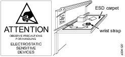
The components inside the product and controller are sensitive to electrostatic discharge. To avoid future malfunction, make sure that service and maintenance is carried out in an ESD approved work environment. The figure below shows an example of an appropriate service work station.
Maintenance Instructions
Preventive Maintenance
Maximize Battery Life
In order to maximize battery life, do not leave the battery connected to the tool if you do not plan to use it for several days. The battery can discharge and go into “sleep mode” which will require a special wake-up charge procedure.
Overhaul
Have your power tool serviced by a qualified repair person using only identical replacement parts. This will ensure that the safety of the power tool is maintained.
Service must only be carried out by qualified personnel who have access to the Service instruction and/or have been trained for service on (these specific) EBB and EBP tools.
The electric motor is a sealed unit and may under no circumstances be opened by anyone else than Atlas Copco Industrial Technique AB.
Overhaul and preventive maintenance is recommended at regular intervals once per year or after maximum 250.000 drilling cycles depending on which occurs sooner. More frequent overhaul may be needed if the machine is used in heavy-duty operations. If the machine not is working properly, it should immediately be taken away for inspection.
When dismantling the tool always use the specially designed service tool 4080 0848 80, (two service tools are required).
Dismantling/Assembling Instructions
Assembling the Chuck
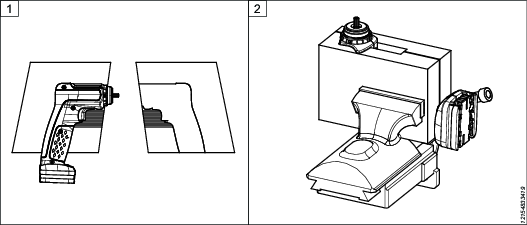
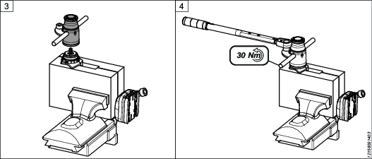
Place the tool in the plastic clamps.
Put the plastic clamps (4080 1133 80) with the motor and handle to a vise.
Assemble the front part of the motor.
Tighten to 30 Nm, left threaded. Use adjustable spanner 4080 0848 80.
Assembling the Planetary Gear
Front Part Assembly
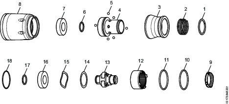
Insert the O-ring (18) into the motor housing.
Insert the 2 O-rings (10 and 11) into the front part (8).
Insert the plug (9) into the front part (8).
Insert the gear rim (12) onto the front part (8).
Assemble the washer (14) and wave washer (15) onto the shaft (13).
Press the ball bearing (16) onto the shaft (13).
Mount the snap ring (17) onto the shaft (13).
Insert the assembled shaft (13) into the front part (8).
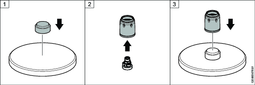
Press the Ball Bearing Into the Front Part
Use the press tool 4080 1131 00 (1) and 4080 1132 00 (4), see image above.
See Front Part Assembly, for the numbers in the bracket.
Place the mounting tool on the press.
Insert the complete planetary gear into the front part. Make sure that when inserted the planetary gear springs.
Put the front part, facing upwards, on the mounting tool.
Insert the ball bearing (7) into the front part (8).
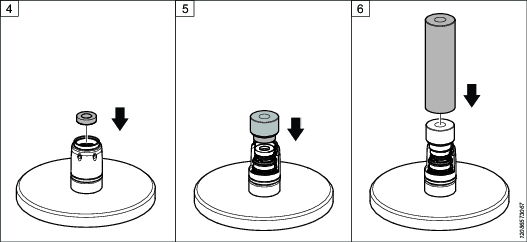
Place the second part of the mounting tool on the top of the front part.
Push down the press.
Press the front part and mounting tool together.
The surface of the front part will show some elevation.
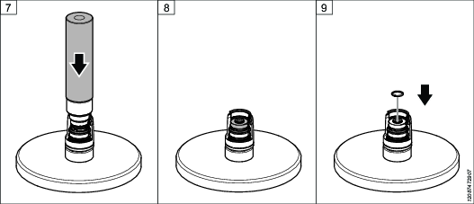
Insert the snap ring (6).
Assemble the connector (4) by following the order below.
Tighten the connector (4), to the front part (8). Tighten left threaded with 10 Nm, use tool 4080 8889 80.
Insert the 6 balls (5) in the holes of the connector (4).
Assemble the locking ring (3) over the connector (4)
Insert the spring (2) to the locking ring (3).
Assemble the snap ring (1).
Outcome of the complete connector.
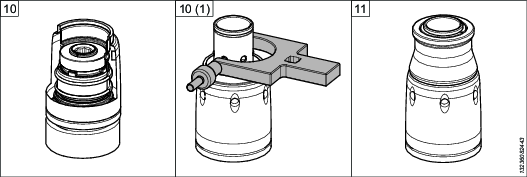
Software Update Status
Not available for all models.
During configuration and software update the tool shows limited content on the display, compared to normal operation.
Light behavior | State | Meaning |
|---|---|---|
Flashing blue | Boot/Configuration mode | A USB cable has been plugged into the tool. The tool is in boot/configuration mode and is/or is ready to be connected to ToolsTalk 2 Service. |
Flashing green | Software update progressing | A software update is in progress. |
Flashing red | Error | The tool has encountered an error during software update or boot up. Connect the tool to ToolsTalk 2 Service for more information. |
Updating the Tool Software
Not available for all models.
For information on updating the tool software, refer to the Copying Firmware section in the ToolsTalk Service 2 User Edition user guide.
To prevent damage to the tool:
Make sure the battery is fully charged when performing a software update.
Do not remove the battery from the tool while the software update is in progress.
Troubleshooting
Overheated Tool
The tool is designed for normal handheld drilling. The tool temperature can be influenced by the following parameters:
Thickness of the material
Type of material
Drilling diameter
Pre-hole size
Drill bit geometry
Rest time between each hole
Thrust force from operator
Number of holes in a series
Troubleshooting Tool Events
Tool events which appears on the display:
Icon display | Light | Event | Tool behaviors |
|---|---|---|---|
| Flashing red | Overheated | The tool will not start drilling. |
| Steady red | Battery empty | The tool will not start drilling. |
| Flashing red | Cutter usage [limit exceeded - no lock] | The tool will start drilling. |
| Steady red | Cutter usage [limit exceeded - lock] | The tool will not start drilling. |
| Flashing red | Service [limit reached - no lock] | The tool will start drilling. |
| Steady red | Service [limit reached - lock] | The tool will not start drilling. |
| Steady red | Wi-Fi Zone Tethering.1 Out of range. | The tool will not start drilling. |
| Steady red | Unrecoverable error:
| The tool will not start drilling. Connect to ToolsTalk 2 Service. |
| Flashing red | Recoverable error:
| The tool will not start drilling. The reason for the event/state will go away. |
1Not available for all models.
Recycling
Environmental Regulations
When a product has served its purpose it has to be recycled properly. Dismantle the product and recycle the components in accordance with local legislation.
Batteries shall be taken care of by your national battery recovery organization.
Recycling Instruction
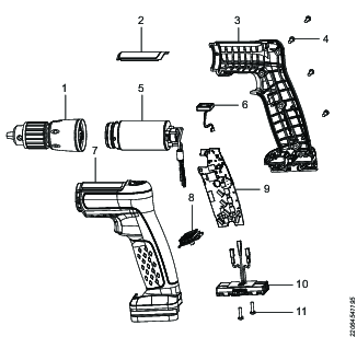
Position | Part | Remarks | Recycle as |
|---|---|---|---|
1 | Front cover | Metal, Steel | |
2 | Marking plate | Metal, Steel | |
3 | Handle | Right | Plastic, Other, PA6GF30 |
4 | Screws | 4 pcs | Metal, Steel |
5 | Motor housing, complete | Electronics | |
6 | Fan | Electronics, Rubber (Sleeve to be recycled as rubber) | |
7 | Handle and trigger | Left | Plastic, Other, PA6GF30 |
8 | Display (HMI) and radio board module | Electronics | |
9 | Main board | Electronics | |
10 | Battery connector | Plastic, Other, PA6 | |
11 | Screws | 2 pcs | Metal, Steel |

