STpad CABLE ADAPTER
Product Information
General Information
Safety Signal Words
The safety signal words Danger, Warning, Caution, and Notice have the following meanings:
DANGER | DANGER indicates a hazardous situation which, if not avoided, will result in death or serious injury. |
WARNING | WARNING indicates a hazardous situation which, if not avoided, could result in death or serious injury. |
CAUTION | CAUTION, used with the safety alert symbol, indicates a hazardous situation which, if not avoided, could result in minor or moderate injury. |
NOTICE | NOTICE is used to address practices not related to personal injury. |
Website
Information concerning our Products, Accessories, Spare Parts and Published Matters can be found on the Atlas Copco website.
Please visit: www.atlascopco.com.
ServAid
ServAid is a portal that is continuously updated and contains Technical Information, such as:
Regulatory and Safety Information
Technical Data
Installation, Operation and Service Instructions
Spare Parts Lists
Accessories
Dimensional Drawings
Please visit: https://servaid.atlascopco.com.
For further Technical Information, please contact your local Atlas Copco representative.
Country of Origin
For the Country of Origin, please refer to the information on the product label.
Dimensional Drawings
Dimensional Drawings can be found either in the Dimensional Drawings Archive, or on ServAid.
Please visit: http://webbox.atlascopco.com/webbox/dimdrw or https://servaid.atlascopco.com.
Overview
General description
The STpad cable adapter is a cabled solution that enables tools testing using STpad when wireless solutions are problematic or infeasible.
Thanks to the STpad cable adapter, it is possible to connect ACTA transducers to an STpad using a standard 19 pins connector military cable.
The STpad cable adapter is designed to be installed on the back of the STpad and it is connected to and powered by the STpad through the USB port.
Product data
Voltage: 5V

Current: 1A (max)
Power: 5W (max)
Environmental Conditions
Indoor use only | |
Altitude | Up to 2000 m |
Ambient temperature range | +5 to +40 °C |
Maximum relative humidity 80 % for temperatures up to 31 °C decreasing linearly to 50 % relative humidity at 50 °C |
|
Pollution degree | 2 |
User interfaces
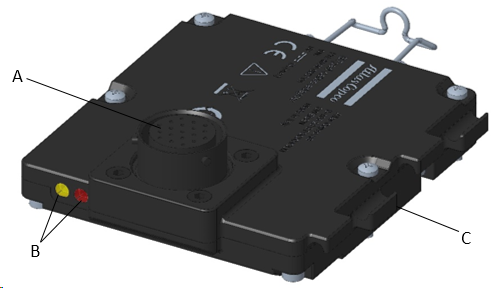
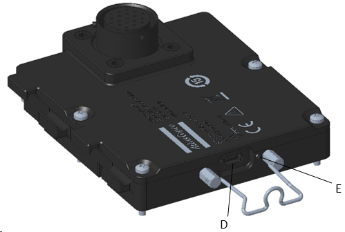
A | Transducer connector | B | LED indicators |
C | USB cable support | D | USB port |
E | Reset button |
Supported transducers
IRTT-B
Torque only models
Model | Capacity [Nm] | Drive | Ordering N. |
|---|---|---|---|
5-I06 | 5 | ¼” hex | 8059 0942 05 |
5-06 | 5 | ¼” square | 8059 0942 07 |
20-I06 | 20 | ¼” hex | 8059 0942 10 |
20-06 | 20 | ¼” square | 8059 0942 15 |
25-10 | 25 | 3/8” square | 8059 0942 20 |
75-10 | 75 | 3/8” square | 8059 0942 25 |
180-13 | 180 | ½” square | 8059 0942 30 |
500-20 | 500 | ¾” square | 8059 0942 35 |
750-25 | 750 | 1” square | 8059 0942 40 |
1400-25 | 1400 | 1” square | 8059 0942 45 |
3000-38 | 3000 | 1 ½” square | 8059 0942 52 |
5000-38 | 5000 | 1 ½” square | 8059 0942 56 |
Torque and Angle models
Models | Capacity [Nm] | Pulses per revolution [*] | Drive | Ordering N. |
|---|---|---|---|---|
1A-I06 | 1 | 256/1024 | ¼” hex | 8059 0943 96 |
2A-I06 | 2 | 256/1024 | ¼” hex | 8059 0943 01 |
5A-I06 | 5 | 256/1024 | ¼” hex | 8059 0943 06 |
5A-06 | 5 | 256/1024 | ¼” square | 8059 0943 08 |
20A-I06 | 20 | 256/1024 | ¼” hex | 8059 0943 11 |
20A-06 | 20 | 256/1024 | ¼” square | 8059 0943 16 |
25A-10 | 25 | 256/1024 | 3/8” square | 8059 0943 21 |
75A-10 | 75 | 256/1024 | 3/8” square | 8059 0943 26 |
180A-13 | 180 | 256/1024 | ½” square | 8059 0943 31 |
500A-20 | 500 | 256/1024 | ¾” square | 8059 0943 36 |
750A-25 | 750 | 256/1024 | 1” square | 8059 0943 41 |
1400A-25 | 1400 | 256/1024 | 1” square | 8059 0943 46 |
3000A-38 | 3000 | 384/1536 | 1 ½” square | 8059 0943 52 |
5000A-38 | 5000 | 384/1536 | 1 ½” square | 8059 0943 56 |
10000A-38 | 10000 | 512/2048 | 1 ½” square | 8059 0943 60 |
SRTT-B
Model | Capacity [Nm] | Drive | Ordering N. |
|---|---|---|---|
SRTT-B 0.5 – 13 | 0.5 | ½” square | 8059 0946 03 |
SRTT-B 2 – 13 | 2 | ½” square | 8059 0946 09 |
SRTT-B 5 – 13 | 5 | ½” square | 8059 0946 15 |
SRTT-B 10 – 13 | 10 | ½” square | 8059 0946 21 |
SRTT-B 25 – 36 | 25 | 36mm hex | 8059 0946 28 |
SRTT-B 50 – 36 | 50 | 36mm hex | 8059 0946 36 |
SRTT-B 100 – 36 | 100 | 36mm hex | 8059 0946 45 |
SRTT-B 250 – 36 | 250 | 36mm hex | 8059 0946 54 |
SRTT-B 500 – 50 | 500 | 50mm hex | 8059 0946 63 |
SRTT-B 1000 – 50 | 1000 | 50mm hex | 8059 0946 75 |
SRTT-B 2000 – 50 | 2000 | 50mm hex | 8059 0946 84 |
QRTT-B
Model | Capacity [Nm] | Drive | Ordering N. |
|---|---|---|---|
20A-10 | 20 | 3/8” square | 8059 0947 13 |
75A-10 | 75 | 3/8” square | 8059 0947 18 |
200A-13 | 200 | ½” square | 8059 0947 23 |
500A-20 | 500 | ¾” square | 8059 0947 28 |
1000A-25 | 1000 | 1” square | 8059 0947 33 |
IRTT
Torque only models
Model | Capacity [Nm] | Drive | Ordering N. |
|---|---|---|---|
5-I06 | 5 | ¼” hex | 8092 1180 05 |
20-I06 | 20 | ¼” hex | 8092 1180 10 |
20-06 | 20 | ¼” square | 8092 1180 15 |
25-10 | 25 | 3/8” square | 8092 1180 20 |
75-10 | 75 | 3/8” square | 8092 1180 25 |
180-13 | 180 | ½” square | 8092 1180 30 |
500-20 | 500 | ¾” square | 8092 1180 35 |
750-25 | 750 | 1” square | 8092 1180 40 |
1400-25 | 1400 | 1” square | 8092 1180 45 |
Torque and Angle models
Models | Capacity [Nm] | Pulses per revolution [*] | Drive | Ordering N. |
|---|---|---|---|---|
1A-I06 | 1 | 256/1024 | ¼” hex | 8092 1182 96 |
2A-I06 | 2 | 256/1024 | ¼” hex | 8092 1182 01 |
5A-I06 | 5 | 256/1024 | ¼” hex | 8092 1182 06 |
5A-06 | 5 | 256/1024 | ¼” square | 8092 1182 08 |
20A-I06 | 20 | 256/1024 | ¼” hex | 8092 1182 11 |
20A-06 | 20 | 256/1024 | ¼” square | 8092 1182 16 |
25A-10 | 25 | 256/1024 | 3/8” square | 8092 1182 21 |
75A-10 | 75 | 256/1024 | 3/8” square | 8092 1182 26 |
180A-13 | 180 | 256/1024 | ½” square | 8092 1182 31 |
500A-20 | 500 | 256/1024 | ¾” square | 8092 1182 36 |
750A-25 | 750 | 256/1024 | 1” square | 8092 1182 41 |
1400A-25 | 1400 | 256/1024 | 1” square | 8092 1182 46 |
3000A-38 | 3000 | 384/1536 | 1 ½” square | 8092 1182 52 |
5000A-38 | 5000 | 384/1536 | 1 ½” square | 8092 1182 56 |
SRTT
Model | Capacity [Nm] | Drive | Ordering N. |
|---|---|---|---|
SRTT 0.5-06 | 0.5 | ¼” square | 8092 1143 15 |
SRTT 2-06 | 2 | ¼” square | 8092 1143 20 |
SRTT 5-06 | 5 | ¼” square | 8092 1143 25 |
SRTT 25-10 | 25 | 3/8” square | 8092 1143 30 |
SRTT 75-13 | 75 | ½” square | 8092 1143 35 |
SRTT 180-13 | 180 | ½” square | 8092 1143 40 |
SRTT 500-20 | 500 | 3/4” square | 8092 1143 45 |
SRTT 1400-25 | 1400 | 1" square | 8092 1143 50 |
MTTS
Model | Capacity [Nm] | Drive | Ordering N. |
|---|---|---|---|
MTTS 1 | 1 | Ø 3 mm | 8432 0822 20 |
MTTS 2 | 2 | Ø 3 mm | 8432 0822 21 |
MTTS 5 | 5 | Ø 3 mm | 8432 0822 22 |
MTTS 10 | 10 | Ø 3 mm | 8432 0822 23 |
MTTS 20 | 20 | Ø 3 mm | 8432 0822 24 |
MTTS 50 | 50 | ¼” hex female | 8432 0822 25 |
MTTS 100 | 100 | ¼” hex female | 8432 0822 26 |
MTTS 200 | 200 | ¼” hex female | 8432 0822 27 |
MTTS 500 | 500 | ¼” hex female | 8432 0822 28 |
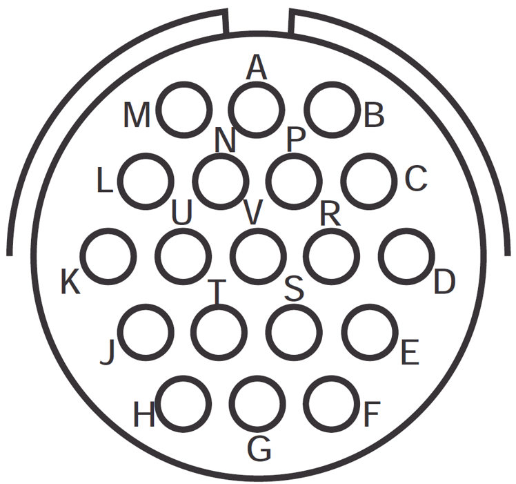
Transducer connector
Use a standard Atlas Copco cable to connect ACTA transducers to the STpad cable adapter.
The connector pinout is as follows:
| PIN | Description |
|---|---|---|
| A | V+ transducer |
B | V- transducer | |
C | Signal + | |
D | Signal - | |
E | Shield | |
F | Phase B encoder | |
H | Phase A encoder | |
P | Ground encoder | |
R | +5.5 V encoder | |
Other pins | Reserved. Do not connect anything. |
LED indicators
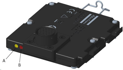
A | Power ON LED | B | RGB LED |
Power ON LED behavior:
Status | Description |
|---|---|
Steady green | Connected and powered by STpad. |
RGB LED behavior:
Status | Description |
|---|---|
Steady blue | Overall status OK and device connected to STpad. |
Blinking cyan | Inspection / tightening in progress. |
Steady white | Bootloader mode. |
Steady red | Device failure: system not initialized or malfunctioning. |
Blinking yellow | Generic error / Warning: detailed description will be reported by STpad. |
USB port
The USB port is used for data exchange and power supply.
Connection to STpad is done via a USB 2.0 type mini-B to USB 2.0 type A cable.
Installation
Installation Instructions
Assembling the cable adapter
Assemble the STpad cable adapter on the back of the STpad with four M2.5x18 mm screws:
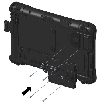
The installation of STpad cable adapter is compatible with all STpad application scenarios (stand-alone, desktop docking station, STbench docking station).
Operation
Ergonomic Guidelines
Consider your workstation as you read through this list of general ergonomic guidelines to identify areas for improvement in posture, component placement, or work environment.
Take frequent breaks and change work positions frequently.
Adapt the workstation area to your needs and the work task.
Adjust for a convenient reach range by determining where parts and tools need to be located to avoid static load.
Use workstation equipment such as tables and chairs appropriate for the work task.
Avoid work positions above shoulder level or with static holding during assembly operations.
When working above shoulder level, reduce the load on the static muscles by lowering the weight of the tool, using for example torque arms, hose reels or weight balancers. You can also reduce the load on the static muscles by holding the tool close to the body.
Take frequent breaks.
Avoid extreme arm or wrist postures, particularly during operations requiring a degree of force.
Adjust for a convenient field of vision that requires minimal eye and head movements.
Use appropriate lighting for the work task.
Select the appropriate tool for the work task.
In noisy environments, use ear protection equipment.
Use high-quality inserted tools and consumables to minimize exposure to excessive levels of vibration.
Minimize exposure to reaction forces.
When cutting:
A cut-off wheel can get stuck if the cut-off wheel is bent or not guided properly. Use the correct flange for the cut-off wheel and avoid bending the cut-off wheel during operation.
When drilling:
The drill might stall when the drill bit breaks through. Use support handles if the stall torque is high. The safety standard ISO11148 part 3 recommends using a device to absorb a reaction torque above 10 Nm for pistol grip tools and 4 Nm for straight tools.
When using direct-driven screwdrivers or nutrunners:
Reaction forces depend on the tool settings and joint characteristics. Strength and posture determine the amount of reaction force that an operator can tolerate. Adapt the torque setting to the operator's strength and posture and use a torque arm or reaction bar if the torque is too high.
In dusty environments, use a dust extraction system or wear a mouth protection mask.
Operating Instructions
Connecting the STpad cable adapter
Connect the STpad cable adapter to the STpad via USB cable. The power indicator glows green.
Connect the transducer to the STpad cable adapter via military cable.
Run the test configured on the STpad (for more information see STpad Configuration manual).

The USB cable connecting to STpad must be kept connected while running a test.
Service
Calibration
The STpad cable adapter must be calibrated at least once a year.
Contact Atlas Copco Service Personnel.
Troubleshooting
Cable adapter disconnecting from STpad
Cause: STpad USB power saving mode settings.
Solution: contact Atlas Copco Service Personnel.
Recycling
Environmental regulations
When a product has served its purpose it has to be recycled properly. Dismantle the product and recycle the components in accordance with local legislation.
Recycling Instructions
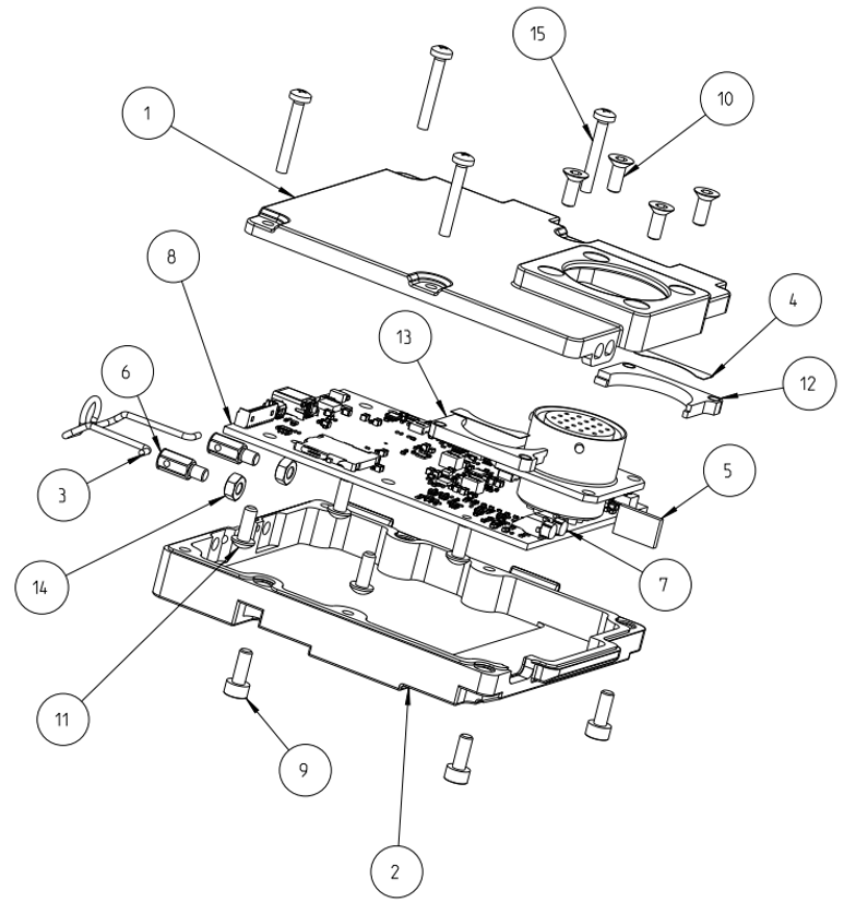
Position | Part | Recycle as |
|---|---|---|
1 | Cover up | Aluminum |
2 | Cover down | Aluminum |
3 | Spring power cable | Steel |
4 | Connector support sticker | Glue |
5 | Light splitter | Foam |
6 | Spring pin | Steel |
7 | Light pipe single | Plastic |
8 | Main board | WEEE |
9 | Screw | Steel |
10 | Screw | Steel |
11 | Screw | Steel |
12 | Military connector internal lower support | Aluminum |
13 | Military connector internal upper support | Aluminum |
14 | Hex nut | Steel |
15 | Screw | Steel |