Battery 14V
Battery
Product Information
General Information
Safety Signal Words
The safety signal words Danger, Warning, Caution, and Notice have the following meanings:
DANGER | DANGER indicates a hazardous situation which, if not avoided, will result in death or serious injury. |
WARNING | WARNING indicates a hazardous situation which, if not avoided, could result in death or serious injury. |
CAUTION | CAUTION, used with the safety alert symbol, indicates a hazardous situation which, if not avoided, could result in minor or moderate injury. |
NOTICE | NOTICE is used to address practices not related to personal injury. |
Warranty
The warranty period of the battery expires 12 months after the battery arrives at the customer, or after 500 charge cycles, whichever occurs first.
"Charge cycle" means any charge of the battery pack that increases the state of charge of the battery by more than 10%.
Normal wear and tear, and loss of performance due to normal wear of the cells is not included within the warranty.
Warranty does not apply if a battery has been abused, misused, opened, dismantled or modified.
Website
Information concerning our Products, Accessories, Spare Parts and Published Matters can be found on the Atlas Copco website.
Please visit: www.atlascopco.com.
ServAid
ServAid is a portal that is continuously updated and contains Technical Information, such as:
Regulatory and Safety Information
Technical Data
Installation, Operation and Service Instructions
Spare Parts Lists
Accessories
Dimensional Drawings
Please visit: https://servaid.atlascopco.com.
For further Technical Information, please contact your local Atlas Copco representative.
Safety Data Sheets MSDS/SDS
The Safety Data Sheets describe the chemical products sold by Atlas Copco.
Please consult the Atlas Copco website for more information www.atlascopco.com/sds.
Country of Origin
For the Country of Origin, please refer to the information on the product label.
Dimensional Drawings
Dimensional Drawings can be found either in the Dimensional Drawings Archive, or on ServAid.
Please visit: http://webbox.atlascopco.com/webbox/dimdrw or https://servaid.atlascopco.com.
Overview
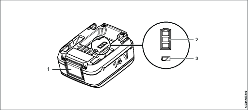
Battery Overview

Position | Description |
|---|---|
1 | Release button |
2 | State of charge indicator |
3 | Status indicator |
Ambient Temperature
For best battery performance and life time, keep battery within temperature intervals.
Operating temperature, charge | +5 to +40 °C |
Operating temperature, discharge | 0 to +40 °C |
Transportation temperature | −20 to +40 °C |
Storage temperature | +10 to +25 °C |
Do not place battery in direct sunlight.
Installation
Installation Instructions
Attaching and Removing the Battery
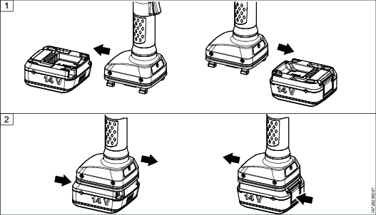
Attach the battery to the tool and make sure that it is fastened correctly. The battery can be attached pointing forward or backward to get the best accessibility and balance.
To remove the battery, press the button on the battery and push it out.

Operation
Operating Instructions
General Operation Safety
Read these safety instructions before use.
Operation
Check the battery pack for damage before every use. Do not use damaged devices.
The battery voltage must match the voltage mentioned on the type plate of the charger and tool.
Use power tools only with specifically designated battery packs. Use of any other battery packs may create a risk of injury and fire.
Do not incinerate, disassemble or crush the battery pack.
Avoid contact with fluids oozing out of defective battery packs. Rinse with water in case of accidental contact with fluid. Consult a doctor if fluid comes into contact with eyes.
Charging
Other chargers than the one stated under Battery Charger Data are not allowed. Charging the battery on a not approved charger is considered as altering the system and will make the tool certification invalid.
Insert only clean and dry battery packs into the battery holder of the charger.
If a protective cover is used on the battery, make sure the cover is removed and look for potential damage before charging.
Check for damage on the battery before charging. Do not charge any battery pack that has been damaged during use or by accident (e.g. dents on the housing or any other damages). Replace damaged battery packs.
We recommend users to remove the battery from the charger once fully charged.
Do not operate the charger close to an explosive environment, for example close to a gas filling station.
We recommend users to operate the charger in a defined protected and secure area (e.g. in charging cabinets or under supervision).
Make sure the charger is stable when charging, to ensure that the batteries do not fall to the floor.
If you identify noise or extensive heat from a battery:
If charging, unplug the charger. Do not remove the battery.
Step away from the battery.
Leave the battery for 12 hours.
Contact your Atlas Copco representative.
Storage
Do not store the battery packs along with metal objects. No metal parts should come in contact with battery connectors; risk of short circuit.
Store batteries and chargers in a dry place, and keep dry at all times.
Avoid storing batteries fully charged.
Do not store your battery connected to the power tool for longer periods
Maintenance charge batteries in storage, preferably every 12 months.
Disposal
Do not dispose of battery packs by throwing them into fire or through household waste.
Starting the Battery
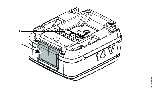
Press the button to start the battery. If sticker (4) is placed over connector and LEDs, remove the sticker before use.

LED Indicators
Autonomous Status Indicators:
Indication | Flash pattern | Battery status | Remark |
|---|---|---|---|
No indication | Good | Battery is healthy and performing well | |
Steady yellow light for 1.5 second | Self-test when powering on | Battery operational after 1.5 second | |
Steady yellow light | Battery cell temperature out of range: | Let battery cool before continuing operation | |
Battery cell temperature out of range: | Make sure ambient temperature is within range | ||
Too high discharge current to tool | Check the tool configuration | ||
Too high charge current | Remove battery from charger and replace charger | ||
Invalid charger | Use appropriate charger | ||
Too high voltage applied externally to battery connector | Use appropriate charger | ||
Steady red light | Unrecoverable error | Replace battery |
State of Charge (SOC) Indicators:
Press release button (1) to show SOC indication (2).
Indication | Battery charge | Remark |
|---|---|---|
Full charge | ||
Medium charge | Charge battery when possible | |
Low charge | Charge battery | |
Empty | Charge battery |
When attaching the battery to the charger, the charging procedure will start and go on for 20 seconds. The charging is then temporarily stopped as the battery performs a self-test. The self-test continues for 10 seconds and after this the battery resumes charging again.
State of Health (SOH) Indicators:
SOH indicates how much of the original capacity that is left in the battery cells, that is, how much the battery has degraded since it was new.
SOH is not an indication of current battery charge.
When the button is pressed for 10 seconds the battery SOH is shown, as listed below:
Indication | Flash pattern | State of Health (SOH) |
|---|---|---|
1 flash, green | More than 80% of the original capacity | |
1 flash, yellow | Between 70-80% of the original capacity | |
1 flash, red | Less than 70% of original capacity |
Manual Status Indicators:
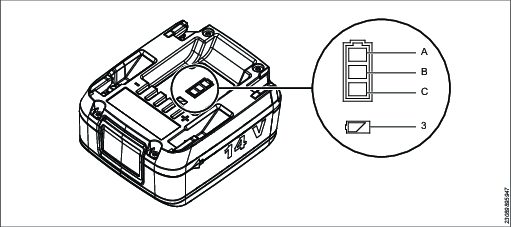
When the release button is pressed for 20 seconds the current battery state is shown by the LEDs in position 3 flashing in sequence, as listed below.
Battery 14V (4211613002) with generation letter A and B is not equipped with a green LED. The green LED is instead indicated with red light, as described in Battery 14V LED behavior for different generation letters.
LED Sequence | Battery State |
|---|---|
Green, green, green | Sleep, normal state |
Green, green, yellow | Idle, normal state |
Green, green, red | Empty, normal state |
Green, green, white | Charge over temperature, transient state |
Green, yellow, green | Charge under temperature, transient state |
Green, yellow, yellow | Discharge over temperature |
Green, yellow, red | Discharge under temperature |
Green, yellow, white | Charge over current |
Green, red, green | Discharge over current |
Green, red, yellow | MOSFET over temperature |
Green, red, red | No parameters |
Green, red, white | Calibration mode |
Green, white, green | Fully charged state |
Green, white, yellow | Discharging |
Green, white, red | Charging |
Yellow, green, green | Transport mode |
Yellow, green, yellow | Powering down |
Yellow, green, red | Cell temperature sensor broken |
Yellow, green, white | MOSFET temperature sensor broken |
Yellow, yellow, green | Cell voltage too low |
Yellow, yellow, yellow | Cell voltage too high |
Yellow, yellow, red | Cells are unbalanced |
Yellow, yellow, white | Pack is over voltage |
Yellow, red, green | Charge MOSFET is broken |
Yellow, red, yellow | Discharge MOSFET is broken |
Yellow, red, red | Initializing at startup |
Yellow, red, white | Discharge off, test mode |
Yellow, white, green | Charge off, test mode |
Yellow, white, yellow | Discharge and charge off, test mode |
Yellow, white, red | Disconnect from charger state |
Yellow, white, white | Charger is invalid |
Red, green, green | Charge software is wrong version |
Red, green, yellow | Charge FET self-test |
Red, green, red | Discharge FET self-test |
Red, green, white | Sum of cell voltages not accurate |
Red, yellow, green | Faulty cell connector |
Red, yellow, yellow | Accumulator over voltage |
Red, yellow, red | Mismatch between temperatures |
Red, yellow, white | Pack over temperature |
Red, red, green | Over charged |
White, white, red | Pack is dead |
Battery Power-off
If the release button is pressed for more than 60 seconds, all three white SOC indicators (2) will flash one by one, in sequence. After 30 seconds of indicators flashing the battery will power-off.
Battery 14V LED behavior for different generation letters
Battery 14V (4211613002) with generation letter A and B is not equipped with a green LED. The difference between generation letter A, B and later generation letters is described in the table below.

LED | Generation A and B | Generation C and onward |
|---|---|---|
A | White | White |
B | White | White |
C | White, red* | White |
3 | Yellow, red | Yellow, red, green |
* same indicator as green in generation C and onwards.
Recycling
Environmental Regulations
When a product has served its purpose it has to be recycled properly.
Batteries shall be taken care of by your national battery recovery organization.


