BCP BL-12-I06
Battery-Powered Screwdriver
Product Information
General Information
Safety Signal Words
The safety signal words Danger, Warning, Caution, and Notice have the following meanings:
DANGER | DANGER indicates a hazardous situation which, if not avoided, will result in death or serious injury. |
WARNING | WARNING indicates a hazardous situation which, if not avoided, could result in death or serious injury. |
CAUTION | CAUTION, used with the safety alert symbol, indicates a hazardous situation which, if not avoided, could result in minor or moderate injury. |
NOTICE | NOTICE is used to address practices not related to personal injury. |
Warranty
Product warranty will expire 12 months after the product is first taken into use, but will in any case expire at the latest 13 months after delivery.
Normal wear and tear on parts is not included within the warranty.
Normal wear and tear is that which requires a part change or other adjustment/overhaul during standard tools maintenance typical for that period (expressed in time, operation hours or otherwise).
The product warranty relies on the correct use, maintenance, and repair of the tool and its component parts.
Damage to parts that occurs as a result of inadequate maintenance or performed by parties other than Atlas Copco or their Certified Service Partners during the warranty period is not covered by the warranty.
To avoid damage or destruction of tool parts, service the tool according to the recommended maintenance schedules and follow the correct instructions.
Warranty repairs are only performed in Atlas Copco workshops or by Certified Service Partners.
Atlas Copco offers extended warranty and state of the art preventive maintenance through its ToolCover contracts. For further information contact your local Service representative.
For electrical motors:
Warranty will only apply when the electric motor has not been opened.
ServAid
ServAid is a portal that is continuously updated and contains Technical Information, such as:
Regulatory and Safety Information
Technical Data
Installation, Operation and Service Instructions
Spare Parts Lists
Accessories
Dimensional Drawings
Please visit: https://servaid.atlascopco.com.
For further Technical Information, please contact your local Atlas Copco representative.
Safety Data Sheets MSDS/SDS
The Safety Data Sheets describe the chemical products sold by Atlas Copco.
Please consult the Atlas Copco website for more information www.atlascopco.com/sds.
Country of Origin
For the Country of Origin, please refer to the information on the product label.
Dimensional Drawings
Dimensional Drawings can be found either in the Dimensional Drawings Archive, or on ServAid.
Please visit: http://webbox.atlascopco.com/webbox/dimdrw or https://servaid.atlascopco.com.
Overview
General Description
The BCP clutch screwdriver is ideal for quality critical joints and applications where flexibility is essential. The slim, well-balanced design and ergonomic pistol grip on the BCP screwdriver makes it a pleasure to hold. With no cables or hoses these screwdrivers are powered by light, high-capacity Lithium-Ion batteries that provide an impressive number of tightenings on one charge. BCP screwdrivers also offer variable speeds and plenty of power within its’ range of torques.
Features
Ergonomic pistol-grip design
Brushless models offering variable speed
Unrivalled clutch design
Speed setting unit for regulating speed
Two strong front lights for best visibility
LED for OK/NOK and battery status Buzzer option
Li-Ion battery technology
Benefits
Low noise level
Excellent torque repeatability and low mean shift
Battery can be mounted in two directions, giving improved accessibility
Technical Product Data
Technical Product Data can be found on either ServAid, or the Atlas Copco website.
Please visit: https://servaid.atlascopco.com or www.atlascopco.com.
Service Overview
Service instructions
Overhaul and preventive maintenance is recommended at regular intervals once per year or after a maximum of 250.000 tightenings. More frequent overhaul may be needed if the tool is used at high torque or with long tightening times. Take out the tool for inspection if it is not working correctly.
At overhaul, clean all parts accurately and replace defective or worn parts.
Lubricate gears and clutch with grease containing molybdenum disulphide, for example Molykote BR2 Plus, refer to the exploded views.
Lubricate o-rings and threaded connections with grease before assembling.
Make sure that all threaded connections on the tool are tightened correctly according to the specifications on the exploded views.
Service Recommendations
Preventive maintenance is recommended at regular intervals. See the detailed information on preventive maintenance. If the product is not working properly, take it out of service and inspect it.
If no detailed information about preventive maintenance is included, follow these general guidelines:
Clean appropriate parts accurately
Replace any defective or worn parts
Operation
Ergonomic Guidelines
Consider your workstation as you read through this list of general ergonomic guidelines to identify areas for improvement in posture, component placement, or work environment.
Take frequent breaks and change work positions frequently.
Adapt the workstation area to your needs and the work task.
Adjust for a convenient reach range by determining where parts and tools need to be located to avoid static load.
Use workstation equipment such as tables and chairs appropriate for the work task.
Avoid work positions above shoulder level or with static holding during assembly operations.
When working above shoulder level, reduce the load on the static muscles by lowering the weight of the tool, using for example torque arms, hose reels or weight balancers. You can also reduce the load on the static muscles by holding the tool close to the body.
Take frequent breaks.
Avoid extreme arm or wrist postures, particularly during operations requiring a degree of force.
Adjust for a convenient field of vision that requires minimal eye and head movements.
Use appropriate lighting for the work task.
Select the appropriate tool for the work task.
In noisy environments, use ear protection equipment.
Use high-quality inserted tools and consumables to minimize exposure to excessive levels of vibration.
Minimize exposure to reaction forces.
When cutting:
A cut-off wheel can get stuck if the cut-off wheel is bent or not guided properly. Use the correct flange for the cut-off wheel and avoid bending the cut-off wheel during operation.
When drilling:
The drill might stall when the drill bit breaks through. Use support handles if the stall torque is high. The safety standard ISO11148 part 3 recommends using a device to absorb a reaction torque above 10 Nm for pistol grip tools and 4 Nm for straight tools.
When using direct-driven screwdrivers or nutrunners:
Reaction forces depend on the tool settings and joint characteristics. Strength and posture determine the amount of reaction force that an operator can tolerate. Adapt the torque setting to the operator's strength and posture and use a torque arm or reaction bar if the torque is too high.
In dusty environments, use a dust extraction system or wear a mouth protection mask.
Operating Instructions
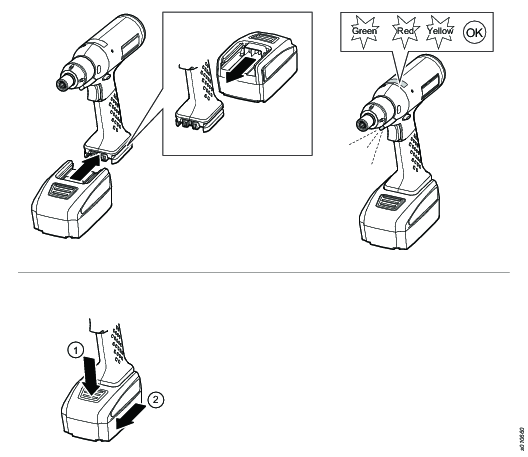
Speed setting unit during charging
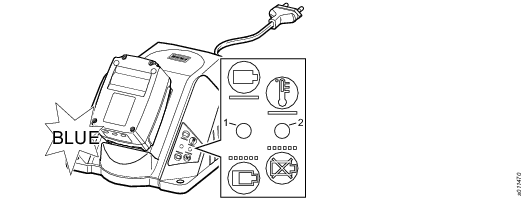
The display light on the speed setting unit flashes when it is put in the charger.
1 Green LED:
The green LED flashes: The battery pack charges.
The green LED is steady lit: The battery is fully charged.
2 Red LED:
The red LED flashes: Contact problems; the battery pack is defective.
The red LED is steady lit: The temperature is too high/low.
Setting tool speed
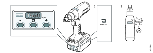
Set the tool speed with + or - button.
Confirm the speed with the enter button.
The LED flashes yellow once when the new speed is confirmed.
RANGE | Min rpm | Max rpm |
|---|---|---|
BCP BL2-I06 (0.8 - 2.5) | 500 | 1550 |
BCP BL6-I06 (2 - 6) | 300 | 1000 |
BCP BL8-I06 (3 - 8) | 300 | 800 |
BCP BL12-I06 (5 - 12) | 250 | 600 |
BCP BL2-L-I06 (0.8 - 2.5) | 150 | 440 |
BCP BL6-L-I06 (1.5 - 6) | 150 | 440 |
BCP BL12-L-I06 (3 - 12) | 150 | 440 |
Adjusting the torque
The tightening torque is adjusted by changing the tension of the clutch spring with the key and the adjustment disc (clutch adjusting kit).
Start at a low torque setting to prevent screw joint damage. If the torque is set too high, there will be no click-sound from the clutch, the green LED will not lit and the motor will be turned off.
Do not adjust the torque over the recommended maximum value as it will result in incorrect function and faster wear.
Put the key in the hole at the front part of the tool.
Turn the key clockwise to increase the tightening torque.
Finish the adjustment at a holding position, located each 1.5 turns of the key.

Controlling the torque
Atlas Copco’s Torque Analyser, ACTA 4000, plus an correctly-sized in-line rotary transducer, such as IRTT, are suitable instruments for controlling the torque.
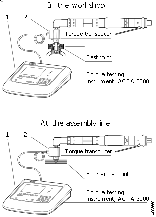
Ref. No. | Ordering No. | Qty | Description | Remark / Included in Service kit |
|---|---|---|---|---|
1 |
| 1 | Torque testing read-out instrument | (Type: ACTA 3000 / FOCUS 2000) See our main catalogue or separate leaflet |
2 | 8092112905 | 1 | Torque transducer | (Type: IRTT 5-I06) See our main catalogue or separate leaflet |
2 | 8092112910 | 1 | Torque transducer | (Type: IRTT20-I06) See our main catalogue or separate leaflet |
| 8092113320 | 1 | ACTA 3000 B |
|
| 8092113330 | 1 | ACTA 3000 QC |
|
| 8092113340 | 1 | ACTA 3000 AA |
|
Standby behaviour (from serial no.A3482445)
To save battery power the tool will switch automatically to a standby mode when it is not used. All LEDs are off in standby mode.
Push the trigger to wake up the tool. Push the trigger a second time to run the tool.
Make sure that the tool is set to the wanted direction.
Standby behaviour (to serial no.A3482444)
To save battery power the tool will switch automatically to a standby mode when it is not used. All LEDs are off in standby mode.
Push the trigger to wake up the tool. The tool starts immediately and runs in a clockwise direction even if it is set to counterclockwise.
Push the trigger a second time to run the tool in the set direction.
Rehit Protection

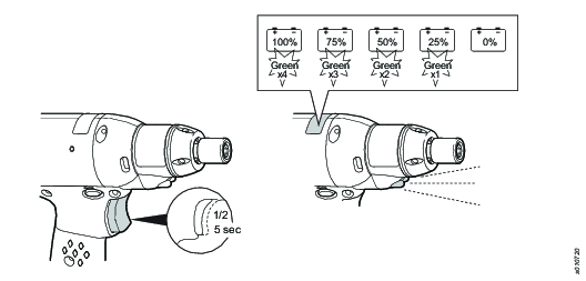
Low Battery Status
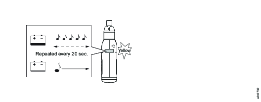
Battery Power Status
A temperature above 50°C reduces the battery perfomance. Do not expose the battery to heat or sunshine.
Changing Screwdriver Bits

Operating the Tool
Make sure that the switch (CW/CCW) is in the clockwise position.
Release the trigger to change the switch.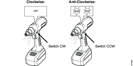
Push the trigger to start the tool.
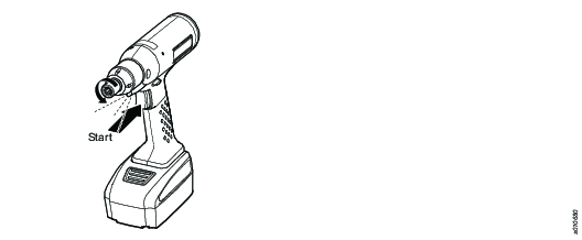
Run the tool until the preset torque is reached and the clutch is released.
A click sound is heard, the LED is green and the motor is turned off.
The LED on the tool notify the tightening status after each tightening. There is no notification if the tool is run in counterclockwise mode.

Battery Packs
Fully charge new or long time unused battery packs before using your battery machine. Full loading capacity of battery pack is reached after 4 – 5 chargings.
The contact points of chargers and battery packs must be kept clean.
If the machine will not be used for 100 hours or longer: separate the battery from the machine. Otherwise the electronics will discharge the battery.
LED Indications
Indication | Status |
|---|---|
No colour, not lit | Screwdriver direction is clockwise. |
Green/Red flashing | Screwdriver direction is counterclockwise. |
Green | Tightening OK, tool is turned off by the clutch. |
Yellow | Battery energy is not sufficient, motor turned off. |
Setting the Tightening Torque
For a safe and accurate operation, set the tightening torque of the screwdriver in relation to the screw joint.
Ref. No. | Ordering No. | Torque rate Nm / rev. | Torque range Nm |
|---|---|---|---|
3 | 4145 0958 80 | 10 | 0.5 – 0.5 |
3 | 4145 0958 81 | 25 | 1.5 – 3.0 |
3 | 4145 0958 82 | 45 | 3.0 – 6.0 |
3 | 4145 0958 83 | 80 | 6.0 – 9.0 |
3 | 4145 0958 84 | 130 | 9.0 – 25.0 |
Ref. No. | Ordering No. | Torque rate Nm / rev. | Torque range Nm |
|---|---|---|---|
3 | 4145 0959 80 | 0.7 | 0.6 – 2.0 |
3 | 4145 0959 81 | 1.5 | 1.5 – 4.0 |
3 | 4145 0959 82 | 3.0 | 3.0 – 7.0 |
3 | 4145 0959 83 | 5.5 | 5.5 – 10.0 |
3 | 4145 0959 84 | 10.0 | 10.0 – 25.0 |
Buzzer
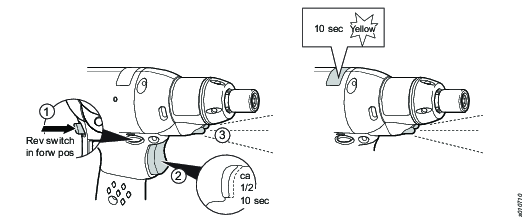
To enable the buzzer function, push and keep the trigger half way.
After 10 seconds the LED flashes orange and the buzzer function is activated.
To disable the buzzer function, repeat the same procedure.
Attaching and Removing the Battery Pack
Attach the battery pack to the tool and make sure that it is fastened correctly. The battery pack can be attached pointing forward or backward to get the best accessibility and balance. To remove the battery pack, push the button on the battery and push it out.
Since a battery pack slowly discharge itself, keep the battery pack in the charging unit that provides a trickle charge.
Service
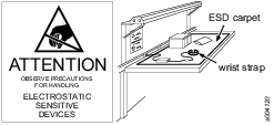
Preventing ESD Problems
The components inside the product and controller are sensitive to electrostatic discharge. To avoid future malfunction, make sure that service and maintenance is carried out in an ESD approved work environment. The figure below shows an example of an appropriate service work station.
Maintenance Instructions
Service instructions
Overhaul and preventive maintenance is recommended at regular intervals once per year or after a maximum of 250.000 tightenings. More frequent overhaul may be needed if the tool is used at high torque or with long tightening times. Take out the tool for inspection if it is not working correctly.
At overhaul, clean all parts accurately and replace defective or worn parts.
Lubricate gears and clutch with grease containing molybdenum disulphide, for example Molykote BR2 Plus, refer to the exploded views.
Lubricate o-rings and threaded connections with grease before assembling.
Make sure that all threaded connections on the tool are tightened correctly according to the specifications on the exploded views.
Service Recommendations
Preventive maintenance is recommended at regular intervals. See the detailed information on preventive maintenance. If the product is not working properly, take it out of service and inspect it.
If no detailed information about preventive maintenance is included, follow these general guidelines:
Clean appropriate parts accurately
Replace any defective or worn parts
Preventive Maintenance
Maximize Battery Life
In order to maximize battery life, do not leave the battery connected to the tool you do not use it for several days. The battery can discharge and go into “sleep mode” which will require a special wake-up charge procedure. For further information, see instructions for multicharger, 4211542485.
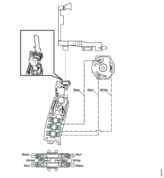
Electric circuit diagram
Lubrication Instructions
Lubrication
Lubricate gears and clutch with grease containing molybdenum disulphide (e.g. Molykote BR2 Plus). Lubricate o-rings and threaded connections with grease before assembling.
For more information, see Spare Parts section in ServAid - https://servaid.atlascopco.com.
Troubleshooting
Overheated Tool
The tool can handle any normal line jobs that an operator sustains with the proper adjustments.
The tool temperature can be influenced by the following parameters:
short cycle time
torque above rated
too low speed
very high prevailing torque
very soft joints
ambient temperature
Error Codes
LED | |
|---|---|
3 red flashes followed by 2 yellow flashes Clutch sensor error. The tool does not start or stops correctly. | |
The signal given by the clutch sensor is out of tolerances. Do a check of the sensor and the magnets for the sensor. Make sure that the flex is connected correctly to the electronic board. If the fault still appears, contact customer service. | |
3 red flashes followed by 3 yellow flashes The temperature is over the maximum limit of 70°C. The tool does not start or stops correctly. | |
The temperature measured with the electronic board is higher than 70°C. Wait for the tool to cool down. When the temperature is lower than 70°C it is possible to operate the tool again. Decrease the tool rate. If the temperature is lower than 70°C and the fault still appears, contact customer service | |
3 red flashes followed by 4 yellow flashes Overheated tool. Too high current over too long time. The tool does not start or stops correctly. | |
The power requested is too big. If the fault still appears, contact customer service. | |
3 red flashes followed by 5 yellow flashes Battery voltage fault. The tool does not start or stops correctly. | |
The battery voltage is not correct for the tool. Make sure that the correct battery is used. If the battery used is correct and the fault still appears, contact customer service. | |
3 red flashes followed by 6 yellow flashes Overcurrent on the power circuit. The hardware limit is reached. The tool does not start or stops correctly. | |
If the fault still appears, the power stage is faulty, contact customer service | |
| 3 red flashes followed by 7 yellow flashes Motor stall. The motor is blocked or the sensors feedback do not fit with the tool drive request. |
Replace the motor. If after replacing the motor the fault still appears, contact customer service. |
Recycling
Environmental Regulations
When a product has served its purpose it has to be recycled properly. Dismantle the product and recycle the components in accordance with local legislation.
Batteries shall be taken care of by your national battery recovery organization.
Recycling information BCP
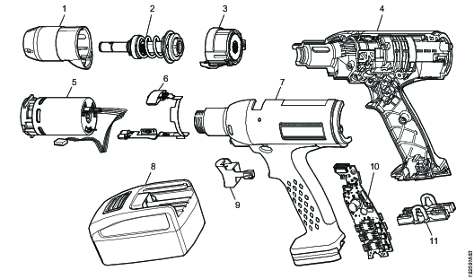
|
Pos. |
Part |
Remarks |
Recycle as |
|---|---|---|---|
|
1 |
Clutch housing |
|
Metal, aluminum |
|
2 |
Clutch |
Metal, steel | |
|
3 |
Gear |
Metal, steel | |
|
4 |
Plastic housing |
Plastics, other, PA | |
|
5 |
Motor |
Electronic | |
|
6 |
Window kit |
Electronic | |
|
7 |
Plastic housing |
Plastics, other, PA | |
|
8 |
Li-Ion battery |
Electronic | |
|
9 |
Trigger |
Plastics, other, PA | |
|
10 |
Circuit board |
Electronic | |
|
11 |
Battery connector |
Plastics, other, PA |


