HLTQ Series
Panel PC
Product Information
General Information
Safety Signal Words
The safety signal words Danger, Warning, Caution, and Notice have the following meanings:
DANGER | DANGER indicates a hazardous situation which, if not avoided, will result in death or serious injury. |
WARNING | WARNING indicates a hazardous situation which, if not avoided, could result in death or serious injury. |
CAUTION | CAUTION, used with the safety alert symbol, indicates a hazardous situation which, if not avoided, could result in minor or moderate injury. |
NOTICE | NOTICE is used to address practices not related to personal injury. |
Warranty
Product warranty will expire 12+1 months after dispatch from Atlas Copco's Distribution Center.
Normal wear and tear on parts is not included within the warranty.
Normal wear and tear is that which requires a part change or other adjustment/overhaul during standard tools maintenance typical for that period (expressed in time, operation hours or otherwise).
The product warranty relies on the correct use, maintenance, and repair of the tool and its component parts.
Damage to parts that occurs as a result of inadequate maintenance or performed by parties other than Atlas Copco or their Certified Service Partners during the warranty period is not covered by the warranty.
To avoid damage or destruction of tool parts, service the tool according to the recommended maintenance schedules and follow the correct instructions.
Warranty repairs are only performed in Atlas Copco workshops or by Certified Service Partners.
Atlas Copco offers extended warranty and state of the art preventive maintenance through its ToolCover contracts. For further information contact your local Service representative.
For electrical motors:
Warranty will only apply when the electric motor has not been opened.
Website
Information concerning our Products, Accessories, Spare Parts and Published Matters can be found on the Atlas Copco website.
Please visit: www.atlascopco.com.
ServAid
ServAid is a portal that is continuously updated and contains Technical Information, such as:
Regulatory and Safety Information
Technical Data
Installation, Operation and Service Instructions
Spare Parts Lists
Accessories
Dimensional Drawings
Please visit: https://servaid.atlascopco.com.
For further Technical Information, please contact your local Atlas Copco representative.
Safety Data Sheets MSDS/SDS
The Safety Data Sheets describe the chemical products sold by Atlas Copco.
Please consult the Atlas Copco website for more information www.atlascopco.com/sds.
Country of Origin
For the Country of Origin, please refer to the information on the product label.
Dimensional Drawings
Dimensional Drawings can be found either in the Dimensional Drawings Archive, or on ServAid.
Please visit: http://webbox.atlascopco.com/webbox/dimdrw or https://servaid.atlascopco.com.
Overview
Applications
The Industrial PC is a computer system which can support several applications, including:
An interface between the factory network and tightening equipment
A platform to operate error proofing systems with PC-based visualization
Technical Product Data
Technical Product Data can be found on either ServAid, or the Atlas Copco website.
Please visit: https://servaid.atlascopco.com or www.atlascopco.com.
Technical Data
Description | Standard (15"/19"/24”) | Configurable | |
|---|---|---|---|
CPU Type | AMD® G-Series GX-424CA (Quad-Core 2.4 GHz), L2 2 MB, 25 W | . | . |
Motherboard | NANO-KBN-i1-4241-R10 | . | . |
RAM | 4 GB, DDR3, FSB 1600/1333 MHz | - | . |
8 GB, DDR3, FSB 1600/1333 MHz | . | optional | |
Mass storage | 64 GB SSD, 2.5“, SATA 3 interface, quick release cartridge | - | . |
128 GB SSD, 2.5“, SATA 3 interface, quick release cartridge | . | optional | |
256 GB SSD, 2.5“, SATA 3 interface, quick release cartridge | - | optional | |
Ports | 1x LAN Gigabit Intel i210-AT, with NCSI support, 1x LAN Gigabit Intel i211-AT, 1x RS232 / RS422 / RS485, each with 5V configurable, 1x extension connector (RJ45) - 7 extension modules connectable, 1x miniPCI express slot, 2x USB 3.0, 2x USB 2.0 (internal accessible), 5x COM RS232, each with 5V configurable, Digital Input: 8 x 24VDC, Digital Output: 8 x 24VDC, 100mA (single) or 400mA (complete) loadable | . | . |
1x USB 2.0 (external accessible) | - | optional | |
Ext. Monitor port | 1x HDMI 1.4a | . | . |
Display | 24 inch; LED TFT, format 16:9, resolution 1920 x 1080 pixel, brightness ≤ 300 cd/m² | . | . |
19": LED TFT, 5:4, 1280 x 1024 pixel, brightness ≥ 350 cd/m² | . | . | |
24": LED TFT, 16:9, 1920 x 1080 pixel, brightness ≤ 300 cd/m² | . | . | |
Touch | glass, resistive | . | . |
RAID system | RAID1 configuration (mirrored system, quick release cartridge for two SSD‘s and second 2.5“ SSD, min. 64 GB necessary, needs miniPCI express slot) | -(1) | optional(2) |
WiFi | WLAN Client Interface (802.11 a/b/g/n) | -/. | optional |
User identification | RFID reader 13,56 MHz and 125 kHz | . | . |
LEGIC reader with ID badge holder | - | optional | |
Fingerprint reader | - | optional | |
Mifare reader | - | optional | |
Euchner reader | - | optional | |
Euchner electronic key system EKS (available on demand) | - | optional | |
Lock | Rittal standard | . | . |
Power supply | 100-240 VAC(Phoenix plug) No powercable is included in delivery! | . | . |
Power rating | max. 70W | . | . |
Current rating | max.1A | . | . |
Mounting | Adapter console Rittal CP 60 (holder for mounting bracket included) | . | . |
Housing | aluminum | . | . |
Protection class | 15" and 19" > IP42 (regarding EN 60529); 24" > IP42 (regarding EN 60529) | . | . |
Operating system | Windows Embedded Standard 7: 64 Bit MUI Pack | . | optional |
Windows 7 Pro: 32 Bit / 64 Bit | - | optional | |
Windows Embedded Standard 7: 32 Bit / 64 Bit | - | optional | |
Size / Weight | 15": 484 x 368 x 70 mm / 12 kg / 26,5 lb (without options, weight of configured options to be added) | . | . |
19": 583 x 434 x 70 mm / 15 kg / 33,0 lb (without options, weight of configured options to be added) | . | . | |
24": 732 x 434 x 70 mm / 21 kg / 46,3 lb (without options, weight of configured options to be added) | . | . | |
(1) Standard RAID Upgrade Kit is with 128GB SSD size only (2) RAID upgrade Kit is with the customer specified SSD size | |||
Internal I/O module
Power supply: | 24VDC (18-30VDC) |
Inputs/outputs: | 8 digital inputs and outputs (24VDC) |
Expandable by adding: | up to 7 extension modules each with 8 inputs and outputs |
Current per output: | 0,5A (max. 3A total) |
Fuse protection: | 3,5A |
Current consumption per input: | 7mA |
Outputs are protected against short circuits, overload, load discharge (inductive voltage spikes) as well as the loss of ground connection.
Reversing the polarity of the supply voltage will destroy the soldered fuse.
Optionally, the ground potentials of the 24VDC inputs can be separated from those of the 24VDC outputs. The maximum permissible potential difference between the grounds is 100VDC.
Service Overview
Spare parts
Parts without ordering number are not delivered separately for technical reasons. The use of other than genuine Atlas Copco replacement parts may result in decreased tool performance and increased maintenance and may, at the company option, invalidate all warranties.
Ref.No. | Size | Ordering No. | Qty | Description | Remark / included in Service kit |
|---|---|---|---|---|---|
1 | 15’ | 4222 6000 25 | 1 | USB Backside | |
19’ | 4222 6000 25 | 1 | USB Backside | ||
24’ | 4222 6000 25 | 1 | USB Backside | ||
2 | 15’ | 4222 6000 13 | 1 | Frontunit RFID identifcation - Touch RS232 | |
15’ | 4222 6000 14 | 1 | Frontunit fingerprint identifcation - Touch R232 | ||
15’ | 4222 6000 00 | 1 | Frontunit RFID identifcation - Touch PS/2 | ||
15’ | 4222 6000 01 | 1 | Frontunit fingerprint identifcation - Touch PS/2 | ||
19’ | 4222 6000 02 | 1 | Frontunit RFID identifcation - Touch RS232 | ||
19’ | 4222 6000 03 | 1 | Frontunit fingerprint identifcation - Touch R232 | ||
19’ | 4222 6000 11 | 1 | Frontunit RFID identifcation - Touch PS/2 | ||
19’ | 4222 6000 12 | 1 | Frontunit fingerprint identifcation - Touch PS/2 | ||
15’ | 4222 6000 58 | 1 | Frontunit RFID identification - Touch RS232 rev. 2 | ||
19’ | 4222 6000 59 | 1 | Frontunit RFID identification - Touch RS232 rev. 2 | ||
15’ | 4222 6000 60 | 1 | Frontunit fingerprint identification - Touch RS232 rev. 2 | ||
19’ | 4222 6000 61 | 1 | Frontunit fingerprint identification - Touch RS232 rev. | ||
24’ | 4222 6000 71 | 1 | Frontunit RFID identifcation - Touch RS232 | ||
24’ | 4222 6000 72 | 1 | Frontunit fingerprint identifcation - Touch R232 | ||
15’ | 4222 6000 63 | 1 | HLT15Q Frontplate with touchscreen | ||
19’ | 4222 6000 64 | 1 | HLT19Q Frontplate with touchscreen | ||
24’ | 4222 6000 73 | 1 | HLT24Q Frontplate with touchscreen | ||
3 | 15’, 19’, 24’ | 4222 6000 17 | 1 | Key lock E1 | |
15’, 19’, 24’ | 4222 6000 18 | 1 | HLT..Q Key lock E14 | ||
15’, 19’, 24’ | 4222 6000 19 | 1 | HLT..Q Key lock Rittal |

Ref.No. | Size | Ordering No. | Qty | Description | Remark / included in Service kit |
|---|---|---|---|---|---|
1 | 15’ | 4222 6000 08 | 1 | Power supply incl. cover & cable | |
19’ | 4222 6000 07 | 1 | Power supply incl. cover & cable | ||
24’ | 4222 6000 74 | 1 | Power supply incl. cover & cable | ||
2 | 15’, 19’, 24’ | 4222 6000 24 | 1 | WLAN 802.11 a/b/g/n with 2 Antennas | |
3 | 15’ | 4222 6000 09 | 1 | Consoleninterfaceboard, incl. cables | |
19’ | 4222 6000 10 | 1 | Consoleninterfaceboard, incl. cables | ||
24’ | 4222 6000 75 | 1 | Consoleninterfaceboard, incl. cables | ||
4 | 15’ | 4222 6000 33 | 1 | Back panel basic | |
19’ | 4222 6000 34 | 1 | Back panel basic | ||
24’ | 4222 6000 76 | 1 | Back panel basic | ||
5 | 15’, 19’, 24’ | 4222 6000 06 | 1 | 64GB SSD, 2,5” | |
15’, 19’, 24’ | 4222 6000 15 | 1 | 128GB SSD,2,5" | ||
15’, 19’, 24’ | 4222 6000 16 | 1 | 256GB SSD, 2,5" | ||
6 | 15’, 19’, 24’ | 4222 6000 20 | 1 | Fingerprint Reader | |
15’, 19’, 24’ | 4222 6000 21 | 1 | Legic Reader phg | ||
15’, 19’, 24’ | 4222 6000 22 | 1 | Legic Reader phg + Badgeholder | ||
15’, 19’, 24’ | 4222 6000 23 | 1 | Mifare Reader phg | ||
7 | 15’, 19’, 24’ | 4222 6000 04 | 1 | Quick Release Cartridge for 2 SSDs | |
15’, 19’, 24’ | 4222 6000 05 | 1 | Quick Release Cartridge for 1 SSD | ||
8 | 15’, 19’, 24’ | 4222 6000 30 | 1 | SBC with displayinterfaceboard | |
9 | 15’ | 4222 6000 53 | Cover plate incl. mounting material and sticker | ||
19’ | 4222 6000 54 | Cover plate incl. mounting material and sticker | |||
24’ | 4222 6000 70 | Cover plate incl. mounting material and sticker |

Installation
Installation Requirements
Connection console – COM

Technical data
A | COM connection 1 |
B | COM connection 3 |
C | COM connection 4 |
D | COM connection 5 |
E | Mains voltage connection |
F | Connections for each of the 8 digital 24VDC outputs |
G | Connections for each of the 8 digital 24VDC inputs |


COM 1 (switchable)
PIN | Pinout @ RS232 S | Pinout @ RS422 | Pinout @ RS485 |
|---|---|---|---|
1 | DCD | TX- | DATA- |
2 | RxD | TX+ | DATA+ |
3 | TxD | RX+ | NC |
4 | DTR | RX- | NC |
5 | Signal Ground | Signal Ground | Signal Ground |
6 | DSR | NC | NC |
7 | RTS | RTS | RTS |
8 | CTS | NC | NC |
9 | RI | NC | NC |
Case | Shielding | Shielding | Shielding |
COM 3, 4, 5
PIN | Pinout @ RS232 |
|---|---|
1 | DCD |
2 | RxD |
3 | TxD |
4 | DTR |
5 | Signal Ground |
6 | DSR |
7 | RTS |
8 | CTS |
9 | RI |
Case | Shielding |
Single Board Computer (SBC)
Additional connections are present on the inside of the rear panel on the Single Board Computer (SBC). To access these connections, the IPC must be opened and closed as described in the section "Opening and closing the Industrial PC".

The connecting cables must run through the connection console (with the cover removed) on the rear side of the Panel PC.
Power supply cord
The power supply cord has to be a 3 wire AWG 16. The length of the power supply cord shall be between 1.5 meters and 4.5 meters. Use one of the cord types: SV, SVE, SVO, SVOO, SVT, SVTO, SVTOO1, SP-2, SPE-2, SPT-2, NISP-2, NISPE-2, NISPT-21, SP-3, SPE-3, SPT-31, SJ, SJE, SJO, SJOO, SJT, SJTO, SJTOO S, SE, SO, SOO, ST, STO, STOO.
1 Types SP-2, SP-3, SV and similar cords may be provided if the cord is not longer than 2,4 meters
External circuit breaker
The Industrial PC has to be installed with an external 2 pole circuit breaker rated current 6A e.g. Eaton FAZ-C6/2.
Installation Instructions
Connecting the power cable
Check and make sure that the power cable is not under any strain when mounted and make sure that the protective conductor is 1.5 times as long as both the other wires. (The Phoenix mains voltage plug is included on delivery.)
Plug the mains plug into the mains socket and fix it in place with both the screws. Screw the cable grip into the connection console/rotating joint with the two enclosed screws. Align the power cable properly and tighten the cable grip (PG fitting).
Activate the external circuit breaker and / or external fuse.

Assembling the Industrial PC
Only appropriately qualified personnel may assemble and operate this device.
Only suspended and raised assembly is permissible.
The bracket is assembled as follows:
Screw in rotating joint (a) to the mounting profile (b) (e.g. Rittal CP 60), using the four to eight screws enclosed with the rotating joint. Remove the cover of the connection console by loosening the three screws.
Then screw together the disassembled connection console (c) with the rotating joint (a). Four screws for this purpose are also included on delivery with the rotating joint.
Preassemble both the top screws first. The original size of these screws is M6x18. The distance between the Panel PC and screw head should be around 13mm. Mount the Panel PC. Then install the two lower screws and tighten all four screws.
Assembled front and side view.
Once all cables have been connected to the Industrial PC, re-position the cover of the connection console in place.
Suspended assembly:

Raised assembly:

Operation
Ergonomic Guidelines
Consider your workstation as you read through this list of general ergonomic guidelines and see if you can identify areas for improvement in posture, component placement, or work environment.
Take frequent breaks and change work positions frequently.
Adapt the work area to your needs and the work task.
Adjust for convenient reach range by determining where parts or tools should be located to avoid static load.
Use workstation equipment such as tables and chairs appropriate for the work task.
Avoid work positions above shoulder level or with static holding during assembly operations.
When working above shoulder level, reduce the load on the static muscles by reducing the weight of the load. You can also reduce the load on the static muscles by holding the load close to the body.
Make sure to take frequent breaks.
Avoid extreme arm or wrist postures, particularly for operations requiring a degree of force.
Adjust for convenient field of vision by minimizing movement of the eyes and head during the work task.
Use the appropriate lighting for the work task.
Use ear protection equipment in noisy environments.
Use dust extraction system or mouth protection mask in dusty environments.
Operating Instructions
Software Installation Requirements
Installation via any of the following methods is possible:
PXE boot (network)
USB stick
External USB DVD hard drive
Hard disk allocation / image distribution via removable hard disk
Calibrating the touch screen
For Industrial PCs with a Serial number from 8066 to 8548 follow these instructions:
Requirements | |
|---|---|
Software | UDDP |
Hardware | External USB keyboard with a built-in trackball |
Localisation | Desktop |
Particularity | Running in Administrator mode |
Connect an external USB keyboard for the purpose of calibration. Navigate to the Windows Start menu > All Programs > UDDP > Kalibrieren.
Press the touch screen in the middle of the black cross. As you release, a green check appears if the calibration point is captured. Repeat this procedure sequentially for each of the four crosses.


For Industrial PCs with a Serial number from 8549 follow these instructions:
Requirements | |
|---|---|
Software | Windows control panel |
Hardware | External USB keyboard with a built-in trackball |
Localisation | Desktop |
Particularity | Running in Administrator mode |
Navigate to Windows > Start > Control Panel > Hardware and Sound > Tablet PC Settings.
Press the “Calibrate…" button. Press the touch screen in the middle of the cross. Repeat this procedure sequentially for each appearing cross until the calibration process is completed.


Opening and closing the Industrial PC
Insert the enclosed key into the locking cylinder. Turn the key through 90° in an anticlockwise direction.


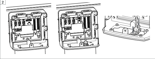
The front panel of the Panel PC folds out automatically when the unit is unlocked.
For HLT24Q please release the safety cord.
Before closing the device, bring the key back into a vertical position and ensure the lock audibly clicks into place when pushing it shut.
Switching the Industrial PC on / off
Open the device as described in the section "Opening and closing the Industrial PC".
The internal power switch is located on the inside of the rear panel. The device can be switched on or off by moving the power switch to position I or O respectively.
Close the device as described in the section "Opening and closing the Industrial PC".

Starting up and shutting down the Industry PC
The Panel PC is automatically started up by moving the power switch to position I, which boots up the operating system.
As is familiar to Windows users, the Industrial PC can be shut down by clicking the start button, whereupon you can then switch off the Panel PC power via the power switch.
To shut down, select Shut Down from the start menu.
Operating the touch screen
Once the touch screen has been calibrated, briefly touching the screen equates to clicking at the relevant point. Touching the screen for longer equates to a right-click. The context menu then opens.
Service
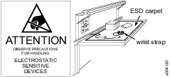
Preventing ESD Problems
The components inside the product and controller are sensitive to electrostatic discharge. To avoid future malfunction, make sure that service and maintenance is carried out in an ESD approved work environment. The figure below shows an example of an appropriate service work station.
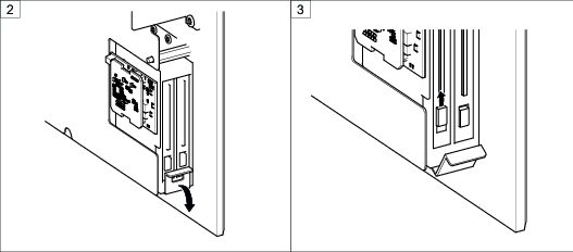
Replacing the hard disk
Open the device, as described in the section “Opening and closing the Industrial PC”. The hard disk mounting is located at the bottom right on the inside of the rear panel.
Release the safety clamp by pressing it downwards.
Push the slider of the hard disk mounting upwards, which opens the flap.
Remove the hard disk from the mounting.
Insert the new hard disk into the mounting, close the flap and re-engage the safety clamp by pushing it upwards.
Close the device, as described in the section “Opening and closing the Industrial PC”.


Replacing the Bios battery
When BIOS buffer battery is replaced, it should be original part type CR2032. Risk of explosion if battery is replaced by an incorrect type. Dispose of used batteries according to the local or regional regulations or instructions.
Maintenance recommendations
The Panel PC can generally be operated without maintenance, but should be cleaned regularly in very dusty environments.
Especially the cooling fins should be kept clean and not be covered by any material and proper ventilation always assured to prevent the computer from overheating.
For preventive maintenance purposes and depending on operating conditions and availability requirements, the power supply and SSD may be replaced as a precautionary measure.
If the device does not function flawlessly, it should be shut down immediately and inspected. During an overhaul, all parts should be carefully cleaned and damaged and worn out parts replaced.
Recycling
Environmental Regulations
When a product has served its purpose it has to be recycled properly. Dismantle the product and recycle the components in accordance with local legislation.
Batteries shall be taken care of by your national battery recovery organization.