Power Focus S (3.14)
Software
Introduction
In this section, you can find the basic information about the product and also the formatting conventions used in the topics.
General Data Protection Regulation (GDPR)
This product offers the possibility to process personal identifiable information such as system user name, role and IP-address. The purpose of this processing capability could be to enhance quality control through traceability and proper access management.
If you decide to process personal data you need to be aware of and comply with relevant personal data protection rules, including, in the EU the GDPR as well as other applicable laws, directives and regulations. Atlas Copco can in no way be held liable for any use made by you of the product.
Conventions
To enhance user understanding, certain formatting conventions are used throughout this document. The formatting conventions used are listed below.
Element | Notation | Description | Output |
|---|---|---|---|
General emphasis | In the Program workspace. | To make certain text elements stand out, or to highlight. | Text in Bold |
Graphical User Interface (GUI) items | Select the Function button. | Any reference to items found on screen in the GUI (for example, command buttons, icon names and field names). | Text in Bold |
Graphical User Interface (GUI) Path > | Generally, on the top of the GUI. | Navigation aid which keeps track of the location in the GUI. | For example: Controller > Program > Edit |
User input | Enter a Description for the program. | Any text input by the user. | Text in Bold |
File names | Enter a File Name for the export. | Files either exported from, or imported into the system. | Text in Bold Italic |
Variable and parameter names | Enter a Name for the export. | Variable and parameter names (not values). | Text in Italic |
Variable and parameter values | Enter a VALUE for the export. | Variable and parameter values. | Text in BOLD CAPS |
System output | Client.Domain.Models.ExportImportConfiguration | Any text output by the system. | Text in Monospace |
External links | Links to external sites that have information connected to the document or subject content. These could include:
| Selectable text to external sites | |
Internal documentation links |
If available, these links will be presented below the text. | Selectable text to internal content |
Liabilities and Warnings
Liability
Many events in the operating environment may affect the tightening process and shall require a validation of results. In compliance with applicable standards and/or regulations, we hereby require you to check the installed torque and rotational direction after any event that can influence the tightening result. Examples of such events include but are not limited to:
initial installation of the tooling system
change of part batch, bolt, screw batch, tool, software, configuration or environment
change of air- or electrical connections
change in line ergonomics, process, quality procedures or practices
changing of operator
any other change that influences the result of the tightening process
The check should:
Ensure that the joint conditions have not changed due to events of influence.
Be done after initial installation, maintenance or repair of the equipment.
Occur at least once per shift or at another suitable frequency.
Safety Signal Words
The safety signal words Danger, Warning, Caution, and Notice have the following meanings:
DANGER | DANGER indicates a hazardous situation which, if not avoided, will result in death or serious injury. |
WARNING | WARNING indicates a hazardous situation which, if not avoided, could result in death or serious injury. |
CAUTION | CAUTION, used with the safety alert symbol, indicates a hazardous situation which, if not avoided, could result in minor or moderate injury. |
NOTICE | NOTICE is used to address practices not related to personal injury. |
About the User Guide
The User Guide describes how to set up and configure the Power Focus S.
It is intended for anyone operating or servicing the Power Focus S.
Revision History
Release Number | Revision Date | Revision Description |
|---|---|---|
item | item | none |
3.11 | 02/2024 | NEW Content UPDATED Content |
3.10 | 08/2023 | First official release of the user guide for Power Focus S. |
Installation and Upgrade
In this section, you can find information to help with the initial installation of the product, or upgrading from one version to another.
Accessing the Web GUI
To access the Power Focus S Web GUI a computer with a browser installed is needed.
Using an ethernet cable, connect the computer to the service port of the Power Focus S.
On the computer, open a browser and go to 169.254.130.2.
The Power Focus S Web GUI opens.
Configuration
In this section, you can find detailed information about how to create, modify, and verify product settings.
Working with the Controller Tab
The system administration tasks for the Power Focus S are handled in the Controller menu. The menu is accessed through the web interface.
Software
The software version available in the POWER FOCUS S is found in the tab Software.
A new software distribution can be installed either by using the web interface or connecting the system to Power Focus 8 or ToolsControl.
The software update is done automatically when the system is connected to Power Focus 8 or ToolsControl. The software will inherit the same software version that is running on Power Focus 8 or ToolsControl.
The software update option is only visible when accessing the web interface from a PC. The software update file must be unzipped before performing the software update.
Updating the Controller Software through the Web Interface
Access the web interface by connecting a PC with a straight-through Ethernet cable (RJ45) to the Service Ethernet port.
Access the system with the IP address 169.254.130.2 from a web browser.On the home screen of the web interface, go to the Controller tab, select Software on the left pane and then go to the Software update window and select Browse.
Browse and select the file with the software available inside the oci folder of the unzipped file and follow the instructions to complete the installation.
Hardware
The Hardware tab contains information about the controller, such as model designation and serial number, and information about the various electronics boards in the controller.
Working with the Settings Tab
This tab is used to set up the controller specific settings, such as channel, language, and network.
Configuration of the Synchronized Tightening
Power Focus S can be configured in two different Synchronized Tightening modes:
Sync member. This mode is used when the system is connected to a Power Focus 8 through a daisy chain connection. The Power Focus S should be set to Sync member mode, and the Power Focus 8 should be set to Sync reference mode.
No sync. This mode is used when the system is connected to ToolsControl through the Factory Ethernet port.
Changing the Mode
Go to the Settings tab on the home screen. Select Synchronized Tightening.
Select the ellipsis icon (...) on the right. The Choose an item pop-up window opens.
Select the preferred mode in the Choose an item pop-up window. Confirm by selecting Apply.
In Sync member mode, the Channel number field will appear. This number sets the channel number of the system when connected to a Power Focus 8.
The system will automatically reboot once the mode change is applied.
Configuration of the Preferences
Preferences contain general settings and language.
Changing the Language
Go to the Settings tab on the home screen. Select Preferences, and go to the Language window.
Select the ellipsis icon (...) next to the name of the current language. The Choose an item pop-up window opens.
Select a language in the Choose an item pop-up window.
Changing the language in the Power Focus 8 will also change the language of the Power Focus S web interface.
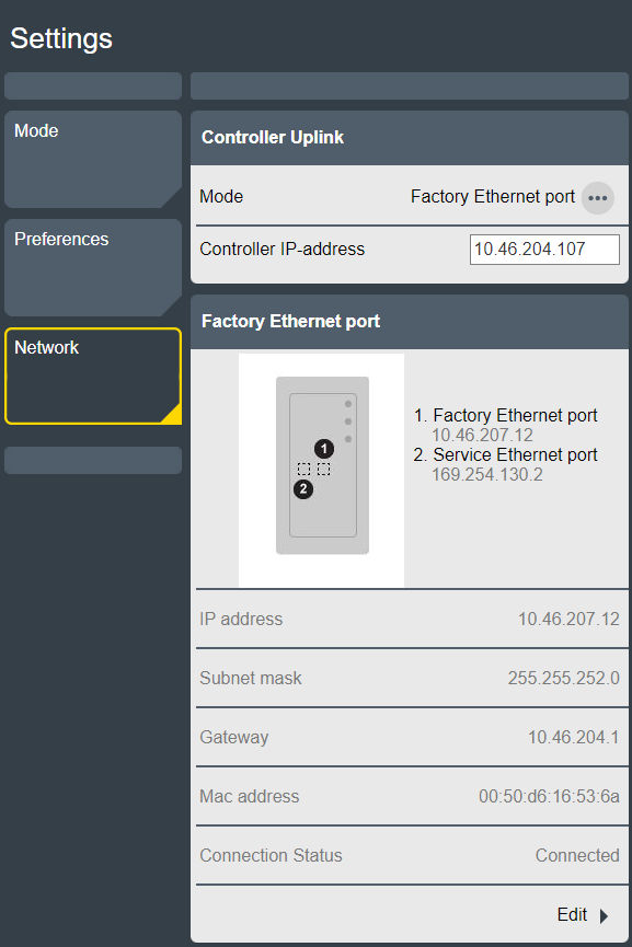
Configuration of the Network
Power Focus S supports two different Controller Uplink modes:
Daisy-chain. This mode is used when the system is connected to a Power Focus 8 and where the Power Focus S is set to Sync member mode.
Factory Ethernet port. This mode is used when the system is connected to ToolsControl.
Changing the Mode
Go to the Settings tab on the home screen. Select Network, and go to the Controller Uplink window.
Select the ellipsis icon (...). The Choose an item pop-up window opens.
Select the preferred mode in the Choose an item pop-up window. Confirm by selecting Apply.

If the Factory Ethernet port mode is selected, the Controller IP-address field will appear. This field is used to set the IP address of the ToolsControl that the system will be connected to.
When the IP address has been added to the Controller IP-address field, the Factory Ethernet port field will appear. Select Edit to change the Ethernet settings of the Power Focus S.
Configuring the Firewall
The controller can be set up to use a firewall. The firewall is based on the trusted host principle, and only allows incoming connections via enabled ports or white-listed addresses.
By default, the firewall is disabled.
The firewall applies only to incoming connections on the Factory Ethernet Port.
Activating and configuring the firewall
In the Home view, select Settings.
Select Network in the left panel.
In the right panel, scroll down to Firewall.
Select Edit and set the Firewall to On. The Port Filtering (layer 4 firewall) and all its predefined filters are enabled by default.
Configure the settings for the different firewall layers by setting services to On/Off or manually enter addresses.
Port filtering (layer 4 firewall): To open and specify reachable services through the firewall.
IP Filtering (layer 3 firewall): To specify a trusted host by IP on the network that can access all the services.
MAC Filtering (layer 2 firewall): To specify a trusted host by MAC.
When no firewall layer is enabled, all incoming connections are let through.
Port Filtering (Layer 4 Firewall)
When the Port Filtering (Layer 4 Firewall) is set to ON, the firewall filter packets based on destination port. Packets sent to an open port are accepted immediately. Non-matching packets are also processed by the other firewall types, IP Filtering and MAC Filtering, before being accepted or rejected.
When the Port Filtering (Layer 4 Firewall) is OFF, the port filtering is disabled and all other options hidden.
Predefined service have their own enable switches:
Open ports for web (TCP 80, TCP 8080)
Open ports for SSH and SFTP (TCP 22)
Open ports for wireless tools (UDP 6677, TCP 6678)
Open ports for accessories (TCP 25000)
Additional TCP ports
Additional UDP ports
Predefined service | Description |
|---|---|
Open ports for web (TCP 80, TCP 8080) | Ports required for web services so the controller is accessible over the factory network. Setting Open ports for web (TCP 80, TCP 8080) to Off, triggers a warning that the connection with the Web HMI can be lost. |
Open ports for SSH and SFTP (TCP 22) | Port required for SSH and SFTP functionality on the Factory Ethernet Port. |
Open ports for wireless tools (UDP 6677, TCP 6678) | Ports required for wireless tools to connect to the controller over the factory network. |
Open ports for accessories (TCP 25000) | Ports required for accessories to communicate with the controller over the factory network. This applies to Socket Selector 6. |
Open additional TCP ports | Accepted are both comma-separated ports and port ranges using a dash (-). Example: when entering 1,2,3,4-10, all ports between 1 and 10 are opened. Invalid port entries trigger an immediate pop-up warning. Ports are automatically sorted after selecting the Apply button. |
Open additional UDP ports |
To use Open Protocol, add the port numbers manually in the Open additional TCP ports entry box. For example: 4545,4546,4547 (depends on the ports configured in Virtual Station > Virtual Station 1 > Protocols > Open Protocol > Server Port).
To use NTP server, add port 123 manually in the Open additional UDP ports entry box.
Multiple ports are added by using comma separation. Port ranges are added by using a dash.
IP Filtering (layer 3 firewall)
To specify trusted host or networks in the IP Filtering (layer 3 firewall), enter their IP addresses in the IP White List entry box. To access the entry box, set the switch to On. Accepted entries are lists of IP addresses or network addresses as IP tables, that is, host IP addresses or network IP addresses. The network mask can be entered as mask length (for example, /24) or as a network IP address (for example, /255.255.255.0). Packets coming from a white-listed IP address are immediately allowed. Other packets are screened by the other firewall layers (Port Filtering and MAC Filtering).
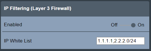
Due to security issues, entering host names or network names is not accepted.
Note that processes like NATing (Network Address Translation) may change source IP addresses. Consult your local network administrator when white-listing a host based on source IP address is required.
MAC Filtering (layer 2 firewall)
MAC Filtering (layer 2 firewall) allows specifying trusted hosts or networks by entering their MAC addresses in the MAC White List entry box. To access the entry box, set the switch to On. Accepted entries are comma-separated lists of MAC addresses. Packets coming from a white-listed MAC address are immediately allowed. Other packets are screened by the other firewall layers (Port Filtering and IP Filtering).
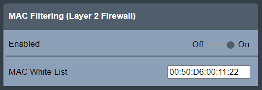
Invalid entries trigger an immediate pop-up warning.
Note that routing may change source MAC addresses. Consult your local network administrator when white-listing a host based on source MAC address is required.
Packet counters
To display the Firewall statistics for each firewall layer, select Settings > Network > Firewall > Packet Counters.
The Update section includes the following buttons:
Refresh: used to refresh the displayed packet counters.
Reset: used to reset the packet counters to zero.
Both buttons has a switch that automatically resets itself to the original position after the action is done.
The Accepted Packet Counters section displays the counters for each of the firewall types and for rejected packets.
Port Filtering: displays the packet counter for packets accepted by the Port Filtering firewall type.
IP Filtering: displays the packet counter for packets accepted by the IP Filtering firewall type.
MAC Filtering: displays the packet counter for packets accepted by the MAC Filtering firewall type.
Rejected: displays the packet counter for packet that were rejected.
The packets accepted, and thus counted, by the Port, IP and MAC Filtering rules only include the initial packets that establish a connection.
The Rejected packets are all counted and displayed.
Firewall status
The status of the general firewall feature and its firewall layers is shown in the Firewall main view directly under Settings > Network.
Status | Description |
|---|---|
OK | The firewall is enabled and the firewall configuration is applied. |
Disabled | The firewall is disabled and the firewall configuration is not applied. |
Configuration Error | The firewall is enabled, but the firewall configuration is not applied due to an internal error. For safety reasons, the fail-open policy is applied, meaning all connections are allowed through. |
When the general firewall status is OK, the status (Enabled / Disabled) for the respective firewall layers is also shown.