Square Drive Tool
Hydraulic Torque Wrench
Produktinformation
Allmän information
KASSERA EJ – GE TILL ANVÄNDAREN
Användningsintyg
Endast för yrkesmässigt bruk.
Denna produkt och medföljande tillbehör får inte modifieras på något sätt.
Använd inte denna produkt om den har skadats.
Om produktuppgifterna eller varningsskyltarna på produkten inte är läsliga eller lossnar ska de bytas omedelbart.
The product must only be operated and serviced by trained and qualified personnel.
Signalord för säkerhet
Säkerhetssignalorden Fara, Varning, Aktsamhet och Observera har följande innebörder:
FARA | FARA är en farlig situation som om den inte undviks, kommer att leda till dödsfall eller allvarliga personskador. |
VARNING | VARNING är en farlig situation som om den inte undviks, kan leda till dödsfall eller allvarliga personskador. |
AKTSAMHET | AKTSAMHET, använt med säkerhetsvarningssymbolen, indikerar en farlig situation som om den inte undviks, kan resultera i mindre eller måttlig skada. |
OBSERVERA | OBSERVERA uppmärksammar om saker som inte är relaterade till personskador. |
Garanti
Produktgarantin upphör att gälla 12 månader efter det att produkten först tas i bruk, men kommer ändå att upphöra senast 13 månader efter leveransen.
Normalt slitage på delar ingår inte i garantin.
Normalt slitage kräver vanligen byte av delar eller annan justering/översyn vid underhåll av standardverktyg under denna period (uttryckt i tid, drifttimmar eller på annat sätt).
Produktgarantin bygger på korrekt användning, underhåll och reparation av verktyget och dess komponenter.
Skador på delar som uppstår som en följd av bristande underhåll eller utförs av andra än parter Atlas Copco eller deras certifierade servicepartners under garantitiden täcks inte av garantin.
För att undvika skador eller förstörelse av verktygsdelar, bör service utföras på verktyget samt underhållsplaner följas enligt anvisningarna.
Garantireparationer utförs endast i Atlas Copco verkstäder eller av auktoriserade servicepartners.
Atlas Copco erbjuder förlängd garanti och toppmodernt förebyggande underhåll genom dess ToolCover kontrakt. För ytterligare information, kontakta din lokala servicerepresentant.
För elektriska motorer:
Garantin gäller endast när den elektriska motorn inte har öppnats.
ServAid
ServAid är en portal som uppdateras kontinuerligt och som innehåller teknisk information, till exempel:
Föreskrifter och säkerhetsinformation
Tekniska data
Installations-, drift- och serviceanvisningar
Reservdelslistor
Tillbehör
Dimensionsritningar
Besök: https://servaid.atlascopco.com.
Kontakta närmaste representant för Atlas Copco om du behöver ytterligare teknisk information.
Säkerhetsdatablad MSDS/SDS
Säkerhetsdatabladen beskriver de kemiska produkter som säljs av Atlas Copco.
Se webbplatsen för Atlas Copco om du behöver mer information www.atlascopco.com/sds.
Ursprungsland
Se informationen på produktetiketten för uppgift om ursprungsland.
Dimensionsritningar
Dimensionsritningar finns antingen i arkivet över dimensionsritningar eller på ServAid.
Besök: http://webbox.atlascopco.com/webbox/dimdrw eller https://servaid.atlascopco.com.
Översikt
Tekniska produktdata
Tekniska produktdata finns antingen på ServAid eller på webbplatsen för Atlas Copco.
Besök: https://servaid.atlascopco.com eller www.atlascopco.com.
Serviceöversikt
Servicerekommendationer
Förebyggande underhåll rekommenderas med jämna mellanrum. Se den detaljerade informationen om förebyggande underhåll. Om produkten inte fungerar som den ska, ta den ur drift och inspektera den.
Om ingen detaljerad information om förebyggande underhåll ingår, följ dessa allmänna riktlinjer:
Rengör tillämpliga delar noga
Byt ut defekta eller slitna delar
Användning
Ergonomiska riktlinjer
Tänk på din arbetsstation när du läser igenom denna förteckning över allmänna ergonomiska riktlinjer, för att komma på områden som kan förbättras när det gäller hållning, placering av komponenter, eller arbetsmiljö.
Ta paus och ändra arbetsställning ofta.
Anpassa arbetsplatsens utseende så att det passar dina behov och arbetsuppgiften.
Se till att allt finns inom bekvämt räckhåll så att verktyg och delar är lättåtkomliga och du undviker statisk belastning.
Använd utrustning som t.ex. bord och stolar som är lämpliga för arbetsuppgiften.
Undvik att arbeta över axelhöjd eller med statiska grepp vid monteringsarbete.
Vid arbeten över axelhöjd, minska den statiska belastningen på musklerna genom att minska verktygets vikt, med hjälp av t.ex. momentarmar, slangvindor eller balanseringsdon. Du kan även minska den statiska belastningen på musklerna genom att hålla verktyget nära kroppen.
Ta regelbundna pauser.
Undvik extrema arm- och handledsställningar, speciellt vid moment som kräver att du tar i.
Justera så att du får ett gott synfält som kräver ett minimum av ögon- och huvudrörelser.
Använd lämplig belysning för arbetet.
Välj lämpligt verktyg för arbetet.
Använd hörselskydd i bullriga miljöer.
Använd högkvalitativa insatta verktyg och förbrukningsartiklar för att minimera exponeringen för kraftiga vibrationer.
Handhavande
Electric Connections
Ensure proper power availability to prevent motor failure or dangerous electrical overloading. Use the recommended amperage listed on the motor nameplate. Do not use electric pump if ground is not connected on plug.
Minimera längden på förlängningssladdar och se till att de har tillräcklig ledararea och är jordade.
Extension cord should be #10 AWG gauge.
General Setup
All our hydraulic torque wrenches are supplied completely assembled, ready for use. An Atlas Copco hydraulic power pack, for use with your Atlas Copco hydraulic torque wrench, is recommended to provide the speed, pressure and portability that make your Atlas Copco System efficient and accurate.
The accuracy of your Atlas Copco hydraulic torque wrench is +/-3% based upon our manufacturer's specifications. This accuracy is certified through calibration tests conducted by Atlas Copco or any other qualified calibration facility whose program is traceable to the National Institute of Standards and Technology (N.I.S.T). We strongly suggest using Atlas Copco certified gauges (with a class 1 accuracy) to enhance the accuracy your torquing system.
Luftanslutning
Ensure that you have sufficient air flow (58 up to 100 PSI / 4 up to 7 bar) to operate you pneumatic pump. If in doubt, compare the pump manufacturer's recommended air flow rating prior to pressurizing pump. Improper air flow may damage the pump motor.
For best results use air hoses equal or larger than 3/4” internal diameter.
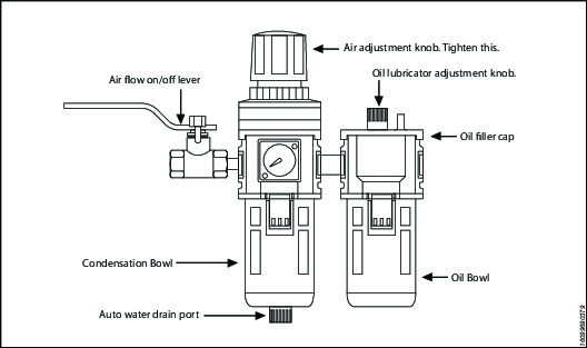
Use of a F.R.L. (Filter Regulator Lubricator) is highly recommended. Fill with oil and adjust the air admission with the adjustment knob.
Hydraulic Connections
Our hydraulic pumps are equipped with a zero-pressure relief valve. However, it could be possible that the retract side remain pressurized after the pump has been switched “off”. This trapped pressure prevents the user from loosening the retract-side fittings by hand. To release the pressure, simply push the black button on top of the solenoid. All fittings are free to be manually tightened.
Never disconnect or connect any hydraulic hoses or fittings without first unloading the wrench and the pump. If the system includes a gauge, double check the gauge to assure pressure has been released. When making connections with quick disconnect couplings, make sure the couplings are fully engaged. Gängade anslutningar som t.ex. kopplingar, tryckmätare, måste vara ordentligt åtdragna och täta.
Arbetstryck
The tool's maximum working pressure is 10,000 psi (700 bar). Make sure that all hydraulic equipment (pumps, hoses, couplers) used with this tool are rated for 10,000 psi (700 bar) working pressure. Review the documentation for the hydraulic pump in use to ensure pressure does not exceed 10,000 psi.
Connecting the System
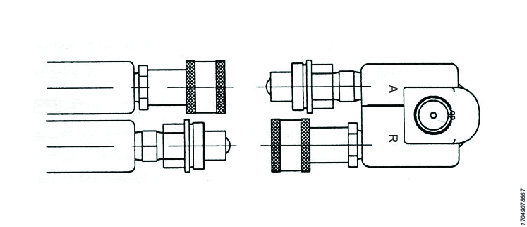
The Atlas Copco hydraulic torque wrench and the power pack are connected by a 10,000 psi (700 bar) operating pressure twinline hose assembly. The safety ratio of the Atlas Copco hydraulic hose is 4/1. On each twin hydraulic hose, one line must be MALE-MALE and the other line must be FEMALE-FEMALE in order to assure a correct interaction between pump and machine. Connect the twinline hose to the swivel as shown:
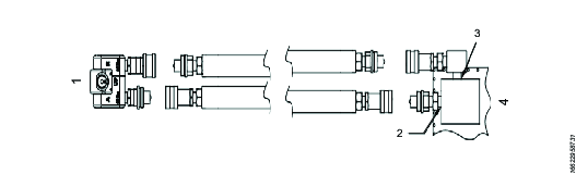
Referens | Beskrivning |
|---|---|
1 | Nyckel |
2 | Port A |
3 | Port 'R' |
4 | Pump |
Check all coupler connections because, after the system has been pressurized, you will not be able to tighten the couplers by hand and using tools will damage the couplers.
Check all coupler connected properly with no gaps between collar and fittings. Never use spanners and other tools to tighten or loose couplers.
Ensure connectors are fully engaged and screwed snugly together.
Never use two twin hydraulic hoses between pump and machine. If so, you have the high pressure on the retract side and your machine will not work properly. To avoid tool malfunction, do not reverse connectors. Do not try to loosen the swivel assembly at any moment.
Operating Hydraulic Pump
Setting Working Pressure on the Pump
To set the pressure on the pump, follow this procedure:
Loosen the knurled locking ring below the "T" handle on the pump's external pressure regulator. Then turn the "T" handle counter clockwise (CCW) until it turns freely and easily.
Turn the pump "on". Using the pump's remote control pendant, push down the advance switch (or button on air pumps) and hold it.
While holding the pump in the advance mode, slowly turn the "T" handle clockwise and observe the pump pressure gauge rise.

Always adjust the regulator in order to increase the pressure up - Never down. Gör aldrig några justeringar med den hydrauliska tryckregulatorn när verktyget är i kontakt med applikationen.
When your gauge reaches 4,000 psi stop turning the "T" handle and let the gauge settle out.
If the pressure continues to rise (above 4,000 psi), release the advance button and back off your pressure slightly-by turning CCW on the "T" handle. Then re-depress the advance switch on you remote and slowly bring pressure up to 4,000 psi again.
When the pressure is correct, turn the pump "off" and tighten the knurled lock nut provided under the "T" handle. This sets pump pressure, which determines torque tool output.
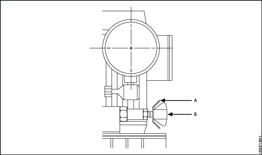
Referens
Beskrivning
A
Låsring
B
T - Handle
Once your target pressure is set and locked, cycle the pump once more to ensure that your pressure setting did not change as you turned down the knurled knob.
Applying Torque to Wrench
Having set your target pressure, cycle the tool three or four times to full pressure. Cycling the tool ensures that the system is operating properly and removes trapped air, if any.
Verify that any impact sockets used are rated to accept the full torque output of the tool they are to be used with. Ensure the correct size impact socket for the nut A/F has been selected, placed on the square drive and secure with a locking pin and ring.
Place the tool and the socket on the nut, making sure that the socket has fully engaged the nut, check that the drive retainer is engaged.
Se till att mothållet ligger an stadigt mot ett fast föremål (t.ex. en närliggande mutter, fläns, kåpa till utrustningen osv.). When positioning the wrench, make sure that the hose connections are well clear of any obstructions and that all body parts are safely out of harm's way. Först i det läget kan man applicera ett tillfälligt tryck i systemet för att säkerställa korrekt verktygsplacering. If it doesn't look or act right, stop and re-adjust the reaction arm.
Read Safety Instructions supplied with the torque wrench for further guidance on tool usage.
By pushing down on the remote control button in the advance position, the rear of the tool will be pushed back until its reaction arm will contact its reaction point.
Continue to hold down the button as the socket turns until you hear an audible "click" which will signify the hydraulic cylinder inside the tool is fully extended and will not turn the advance further.

Continuing to hold down the remote control button will result in a rapid build up of pressure to the point of where the gauge reads what was preset prior to applying the wrench.
The reading of full preset pressure after the cylinder is extended DOES NOT INDICATE that this pressure (torque) is applied to the bolt. It only indicates that the cylinder is fully extended and cannot turn the socket or the ratchet link further until the tool automatically resets itself.
Releasing the remote control button will retract the cylinder. The tool will automatically reset itself and the operator will hear an audible "click" indicating he can again push the remote control button and the socket will turn. Each time the cylinder is extended and retracted, it is called a cycle. Successive cycles are made until the tool "stalls" at the pre-set Torque/psi with an accuracy of +/-3%. Repeatability is +/- 1%.
Always attempt one final cycle to ensure the "stall" point has been reached.
Should the tool "lock-on" after the final cycle, push down on the remote control button once more (to build pressure) and, while maintaining this pressure, pull back on the external disengagement lever (RT) or reaction Pawl (RTX). Releasing the remote control while continuing to hold back on the pawl lever/reaction pawl will allow the tool to be removed easily.
Loosening Procedures
First, set the pump to 9,000 psi (Do not try directly at 10.000 psi). Change the drive and the reaction arm to the loosening mode (Left = Loose), assuring the reaction arm abuts squarely off a solid reaction point. Press and hold the remote control button down. Pressure will decrease as the socket begins to turn. As the cylinder extends fully, you will hear an audible "click". Release the remote control button, and the cylinder automatically retracts, at this time you will again hear the audible "click". Repeat this process until the fastener can be removed by hand.
If the bolt does not loosen with the above procedure, it is an indication that you need a larger tool to loosen the bolt.
Setting Torque
All Atlas Copco power packs operate at a pressure range from 500 to 10,000 psi and are fully adjustable. They have been engineered and designed for portability and high flow for increased speed. Before using your Atlas Copco power pack, check the following points.
Is the reservoir filled with oil?
Where is the closest electrical outlet at the job site?
Is there enough air pressure (60 to 100 psi) and Air flow at the job site? (Air units only)
Is the gauge mounted and rated for 10,000 psi / 700 bar?
Arbetstryck
The pump's maximum working pressure is 10,000 psi / 700 bar. Make sure all hydraulic equipment and accessories are rated for 10,000 psi / 700 bar operating pressure. Hydraulic pumps are available with higher pressure outputs, if not using an Atlas Copco power pack verify maximum operating pressure of the unit being used and ensure the system maximum operating pressure (10,000 psi / 700 bar) is not exceeded.
Hydraulic Connections
Never disconnect or connect hydraulic hoses or fittings without first unloading the wrench. Unplug the electrical cord of the pump, and open all hydraulic controls several times to assure that the system has been depressurized. If the system includes a gauge, double check the gauge to assure pressure has been released. When making a connection with quick disconnect couplings, make sure the couplings are fully engaged threaded connections such a fittings, gauges etc. must be clean and securely tightened and leak free.
Loose or improperly threaded couplers can be potentially dangerous if pressurized, however, severe over tightening can cause premature thread failure. Kopplingar måste vara ordentligt åtdragna och läckagefria. Du får aldrig ta tag i, röra vid eller på något annat sätt komma i kontakt med ett hydrauliskt tryckläckage. Utsprutande olja kan tränga genom huden och orsaka skador. Do not subject the hose and potential hazard such as sharp surfaces, extreme heat or heavy impact. Do not allow the hose to kink and twist. Inspect the hose for wear before it is used.
Electrical Power
Check the proper electrical supply before connecting.
This motor may spark. Do not operate in an explosive atmosphere or in pressure of conductive liquids.
Do not use a power or extension cord that is damaged or has exposed wiring.
All single phase motors come equipped with a three prong grounding type plus to fit the proper grounded type electrical outlet. Do not use a two prong ungrounded extension cord as the pump's motor must be grounded.
Jämför motorns märkskylt mot den spänning som är tillgänglig för att förhindra att motorn bränns ut eller att en farlig elektrisk överbelastning uppstår.
Prior to Use
Check hydraulic oil (Use Atlas Copco maximiser range Grade 46) level to prevent possible pump burnout. Open the filler plug located on the reservoir plate. Look at oil fill level on the oil sight gauge. The oil level should be approximately 2" from the top of the reservoir plate- with motor off. Add oil as necessary. Do not mix different grades of oil. Make sure all desired gauge, valve, hose and quick coupler connections are tight and secure before operating. The use of a pressure gauge is required for normal pump operation. Mounted on the manifold, the gauge permits the operator to monitor the load on the wrench. Class1 certified calibrated gauges are available for most applications.
Operating Square Drive
Changing Drive Direction
To remove the square drive, push the round button on the drive retainer and gently pull on the square end of the square drive (for RT20, 25 & 50, push on the drive retainer while turning it counter-clockwise). To insert the drive in the tool, place the drive in the desired direction, engage drive and bushing splines, then twist drive and bushing until ratchet Spline can be engaged. Push drive through ratchet.
Push drive retainer button, engage retainer with drive and release button to lock the square drive in position.
Reaction Arm
All Atlas Copco hydraulic torque wrenches are equipped with a universal reaction arm. These reaction arms will absorb and counteract forces created as the unit operates. The reaction arm should extend in the same direction of the square drive; however, slight adjustments may be made to suit your particular application. The RT reaction arm is made of special aircraft alloy and is 360° adjustable.
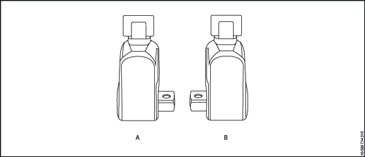
Referens | Beskrivning |
|---|---|
A | Right = Tight |
B | Left = Loose |
The standard RT reaction arm cannot be welded on and should not be modified.
The reaction arm for all RT Monobloc Housing is splined to slide over the rear (cylinder) portion of the tool. In operation, the reaction arm must be fully engaged and secured by inserting the spring loaded reaction arm lever at the base of the housing (end cap). Se till att mothållet är helt låst före användning.
Setting Torque
Once the system is fully connected and proper power supply available, the operator may now adjust the pump pressure to the level needed for the application.
When tightening, use the manufacturer's specifications to determine the torque value which you will ultimately require.
Torque sequence may vary from plant to plant and even within individual plants, depending upon the gasket material, etc. Always follow local procedures.
Refer to the pressure-torque conversion table applicable to the tool which you intend to use, Torque chats are available on ServAId .
Square/Allen Drive Working Torque
Medbringarstorlek The square or hex drive of each drive is limited in its maximum output by its material and its engagement area. Since Atlas Copco uses a specially suited alloy-steel for its drive members, the following maximum torque output can be achieved without drive failure, provided the reaction member abuts close to the same plane as the nut to be turned.
If the reaction arm cannot abut on the same plane as the nut to be turned, less torque should be applied, as the additional side load has to be taken into consideration. When toque requirements are close in excess of the values listed above, use RT's/-9/ Sockets Hex-Drive with replaceable Hex Insert Bits.
RT series is available with square drive (standard) or option hexagonal/Allen drive. The table below reviews ideal working range for the respective drives.
Medbringarstorlek Inch or mm | Drivningstyp | Maximalt arbetstryck | Probable Failure | ||
ft lb | Nm | ft lb | Nm | ||
1/2" | hexa- | 353 | 478 | 392 | 531 |
1/2" | Kvadrat | 367 | 497 | 408 | 553 |
5/8" | hexa- | 689 | 934 | 766 | 1038 |
3/4" | hexa- | 1191 | 1614 | 1324 | 1794 |
3/4" | Kvadrat | 1239 | 1679 | 1377 | 1865 |
7/8" | hexa- | 1892 | 2565 | 2102 | 2848 |
1 tum | hexa- | 2824 | 3827 | 3138 | 4252 |
1 tum | Kvadrat | 2937 | 3980 | 3263 | 4422 |
1 - 1/8" | hexa- | 4021 | 5448 | 4468 | 6054 |
1 - 1/4" | hexa- | 5516 | 7474 | 6129 | 8304 |
1 - 3/8" | hexa- | 7341 | 9948 | 8157 | 11053 |
1 - 1/2" | hexa- | 9531 | 12915 | 10590 | 14350 |
1 - 1/2" | Kvadrat | 9912 | 13432 | 11014 | 14924 |
1 - 5/8" | hexa- | 12118 | 16420 | 13465 | 18245 |
1 - 3/4" | hexa- | 15135 | 20508 | 16817 | 22787 |
1 - 7/8" | hexa- | 18616 | 25224 | 20684 | 28027 |
2 tum | hexa- | 22593 | 30613 | 25103 | 34015 |
2 - 1/4" | hexa- | 32168 | 43588 | 35742 | 48431 |
2 - 1/2" | hexa- | 44126 | 59791 | 49029 | 66435 |
2 - 1/2" | Kvadrat | 45891 | 62183 | 50990 | 69092 |
12mm | hexa- | 298 | 404 | 331 | 449 |
17mm | hexa- | 847 | 1147 | 941 | 1275 |
19mm | hexa- | 1182 | 1602 | 1313 | 1780 |
22mm | hexa- | 1835 | 2486 | 2039 | 2763 |
24mm | hexa- | 2382 | 3228 | 2647 | 3587 |
27mm | hexa- | 3392 | 4596 | 3769 | 5107 |
32mm | hexa- | 5647 | 7652 | 6275 | 8502 |
36mm | hexa- | 8040 | 10895 | 8934 | 12105 |
41mm | hexa- | 11878 | 16094 | 13197 | 17882 |
46mm | hexa- | 16774 | 22730 | 18638 | 25255 |
50mm | hexa- | 21542 | 29190 | 23935 | 32433 |
Service
Underhåll
Rekommendationer för service och underhåll
Använd alltid slagtåliga ögon- och ansiktsskydd om du arbetar med eller uppehåller dig i närheten av verktyg som används, repareras eller underhålls eller verktygstillbehör som byts ut. Handskar och skyddskläder rekommenderas.
Undersökning, underhåll och reparationsarbeten får endast utföras när hela systemet har noll tryck.
För optimala prestanda ska du regelbundet kontrollera verktyg, batteri, slangar, kopplingar, elkablar och tillbehör visuellt så att eventuella skador upptäcks. Följ alltid anvisningarna för underhåll av verktyg och pump.
Riktlinjer för serviceintervall
Med rätt underhållsschema kan utbildad personal använda hydrauliska nycklar i många år utan problem. Alla verktyg slits dock efter lång tids användning. Faktorer som påverkar verktygets livslängd:
Hög arbetscykelfrekvens
Användning med hög belastning
Påverkan
Arbete i smutsiga, varma eller fuktiga miljöer
Olika reaktionsmetoder
Bristfälligt underhåll
Regelbunden smörjning och översyn rekommenderas för att kontrollera att skruvdragaren alltid är i gott bruksskick. Tätare serviceintervall kan behövas vid höga moment, hög produktivitet eller långa åtdragningstider. Om skruvdragaren inte fungerar korrekt ska du omedelbart ta den ur drift och genomföra en inspektion.
Följande serviceintervall är endast avsedda som vägledning. Alla uppgifter och tillämpningar är olika och det är slutanvändarens ansvar att planera lämpligt underhåll som passar arbetsmiljön och användningen. Dokumentera verktygets användning. Denna dokumentation underlättar planering av service, kalibrering och byte av verktyg eller komponenter.
Lättare uppgifter
Exempel: Oregelbunden användning vid låga tryck, <40 % kapacitet.
Smörjning: 6 månaders intervall
Översyn: 12 månaders intervall
Normala uppgifter
Exempel: Regelbunden användning, <80 % kapacitet.
Smörjning: 3 månaders intervall
Översyn: 12 månaders intervall inklusive byte av drivtapp. Se avsnittet Smörjning.
Tunga uppgifter
Exempel: Oavbruten användning vid alla tryck: använd >80 % kapacitet, regelbunden lossning av fastrostade skruvar.
Smörjning: 1 månads intervall
Översyn: 6 månaders intervall inklusive byte av drivtapp och drivspärr. Se avsnittet Smörjning.
Byte av verktyg
Produktägaren måste implementera en serviceplan för policyn för utbyte av verktyg. Denna policy säkerställer att verktyg som används i driften byts ut innan de inte längre är användbara. På grund av olika driftsmiljöer och eventuella skillnader i underhåll av verktygen är det svårt att ange verktygens livslängd.
Visuella tecken på slitage, såsom repor, bucklor eller saknat material, indikerar att verktyget inte längre är användbart. Serva verktyg som visar tecken på slitage. För att bibehålla verktygens skick ska skadade delar bytas ut. Om verktyget uppvisar stora skador på de tryckbärande komponenterna eller mothållsarmarna ska verktyget tas bort av säkerhetsskäl.
Mer information finns i riktlinjerna för serviceintervall.
Förebyggande underhåll
För att hålla det hydrauliska momentdragarsystemet i gott driftsskick ska följande underhåll utföras efter varje användningsperiod.
Torka rent alla utvändiga ytor och gör en visuell kontroll av verktyget och titta efter tecken på skador. Utred vid behov.
Kontrollera alla hydraulkopplingar och fogar avseende tecken på hydraulläckor. Utred vid behov.
Kontrollera att alla hydraulkopplingar är rena och fria från skräp.
Kontrollera slangens hela längd och titta efter skärskador eller nötning. Var uppmärksam på svedda ändar och titta efter tecken på läckor.
Om utrustningen är i gott bruksskick kan du spraya med lämplig rostskyddsolja, till exempel Shell Ensis eller Castrol Rustillo, och ställa undan utrustningen till nästa gång.
Anvisningar för översyn
Anslut dragaren till en pump.
Gör ett trycktest och förvissa dig om att alla mekanismer fungerar som förväntat.
Kontrollera alla funktionsfel eller hydraulläckor.
Gör systemet trycklöst och koppla ur alla kopplingar.
Demontera skruvdragaren.
Byt ut alla tätningar och fjädrar.
Byt ut drivtappen.
Byt ut alla andra komponenter som visar tecken på skador eller slitage.
Smörj och återmontera skruvdragaren.
Gör ett trycktest och kontrollera att alla mekanismer fungerar som förväntat.
Kalibrera skruvdragaren och kontrollera att utgående moment stämmer.
Smörjning
Smörjningsanvisningar
Drivenhetens komponenter | Molykote 1000 |
Tätningar | Rocol Sapphire Aqua-Sil |
Fästelement | Loctite 243 |
Avsmalnande hydraulgängor | Loctite 577 |
Smörjning
För att hålla skruvdragaren i gott driftsskick ska du smörja drivningens komponenter regelbundet mellan serviceintervallen.
Demontering före smörjning:
Ta bort fyrkanttappen.
Ta bort åtkomstpluggarna [×2].
Ta bort kåpans skruvar [×2] samt kåpan.
Ta bort låsklämmorna [×2].
Ta bort drivhylsorna [×2].
Placera drivtappen i linje med åtkomstpluggens hål. Tryck ut sprinten ur huset så att drivenheten frigörs.
Ta bort drivenheten från huset.
Utför följande vid smörjunderhåll:
Kontrollera om drivtappen har tecken på slitage eller skador. Byt ut sprinten om så behövs.
Kontrollera om det finns tecken på skador på spärrhakarnas tandkanter. Byt ut spärranordningen om så behövs.
Kontrollera om det finns tecken på skador på drivspärrens tandkanter. Byt ut drivspärren om så behövs.
Kontrollera om det finns tecken på skador på drivspärrens fjädrar. Byt ut fjädrarna om så behövs.
Smörj de skuggade områdena med Molykote 1000.
Rutinen vid montering är samma som vid demontering men i omvänd ordning.
Felsökning
Troubleshooting of Hydraulic Torque Wrench
Tool failure, although rare, does occur. Such failure is most often in the hydraulic couplers or hoses. These items are repairable or replaceable immediately, since they are available universally. Failures of structural members of the tool are quite rare, however, replacement parts are available from stock. All repairs to Atlas Copco tools may be made by reasonably experienced individuals according to the aforementioned instructions. Otherwise, please contact Atlas Copco to schedule a quick repair of the tool.
Recommended Service intervals are :
Heavy duty use or use in corrosive/harsh environments – every 3 months internal drive components may require frequent inspection and re-lubrication under heavy duty cycles, e.g. weekly.
Normal use – every 6 months.
Light or infrequent use – every 12 months.
Troubleshooting Powerpacks
Atlas Copco Hydraulic Power Packs are precision-built units and, as such, do require a certain amount of care and maintenance
Hydraulic Oil should be completely changed after every 300 hours of operation, or at least twice a year. Always make sure the reservoir is filled with fluid. Always use Atlas Copco Maximizer range of oils for best performance.
Couplers and fittings should be checked periodically for leaks. Dirt or foreign materials should be kept away from fittings. Clean before use.
Hydraulic Gauge: TITAN-mätare är vätskefyllda. Skulle denna vätskenivå sjunka, betyder det ett yttre läckage, och den måste bytas ut. Om mätaren fylls med hydraulolja, betyder det ett internt fel och den ska kasseras.
Filter on Pump: The filter should be replaced twice a year in normal use and more often if the pump is used daily or in a dirty, harsh environment.
Fjärrkontroll (Air Unit) The airline to the remote control unit should be checked for obstructions or kinks in the line periodically. If there is a bend or break in the line, it must be replaced. The spring- loaded buttons on the remote handle should be checked in the event of operating difficulties. (Electric Unit) The switch buttons should be checked periodically if any indications of problems exist.
Air Valve: This valve should be checked twice a year.
Armature: (Electric Unit) Check yearly.
Pumping unit: Pumpen bör ses över vartannat år. Detta kan göras av TITAN eller av ett kvalificerat hydrauliskt servicecenter.
Troubleshooting Routines
Test 1
Attach hoses to pump and tool in the normal manner.
Press the advance button and hold it down.
If the pump pressure builds and the hoses "flex" but the tool still refuses to cycle, the problem is most likely a loose or defective coupling connection. To find out where the bad coupling is, remove the tool from the hoses and marry the loose ends together and cycle the pump. If the gauge pressure reads no more than 500 PSI, then the bad fitting is on the tool. A significantly greater pressure indicates that the problem is in either the pump or a hose fitting.
Test 2
Remove screws from pump motor to reservoir, slide pump motor to the back while keeping pistons into oil.
Turn pump on. If you have no oil coming out from the solenoid tube, change the solenoid.
Tight the regulating valve to maximum, Push on the advance button and while holding down, look if any oil is coming out from the regulating tube. If oil is coming out, change the regulating valve.
Test 3
Remove tool from hoses.
Cycle pump.
If pump fails to build pressure, the problem is with the pump. If it does build pressure, the problem is with hydraulic blow-by in the tool.
Test 4
This test should be run prior to every use of an Atlas Copco Tool
Connect the tool, pump and hoses together as normal.
Cycle the pump several times.
Cycle the system once more and observe the sequence of operation.
As you depress the advance button, the tool drive shroud turn about 24 degrees and you should hear an audible "click". You will also notice that the disengagement levers will move to the rear of the tool and spring forward.
At this point, release the advance button. You should see no further movement and after a moment you will hear another audible "click". This is how the tools are designed to operate.
If you observe any other sequence of operation, the system is out of order and cannot deliver more than 10% of its designed capacity.
Take immediate corrective action. For reference, tools and pumps are designed from the factory plumbed as follows. This ensures that the tool, pump and ONE hose cannot possible be connected up incorrectly.
Test 5
Verktyg | Slang | Pump |
|---|---|---|
Advanced Side-Male | Advance side- Female to Female | Advance side-Male |
Retract side-Female | Retract Side-Male to Male | Retract Side-Female |
Note that connecting two (or any even numbers) of hoses together creates "one" hose which is plumbed backwards! Male to Female and Female to Male. This will cause the system to operate backwards per Test #5 above. If you hose isn’t long enough, connect 3 hoses together, move your pump or call Atlas Copco for a longer hose assembly.
Felsökning Symptom och nödvändig åtgärd
Symptom | Probable Cause | Required Action |
|---|---|---|
Gauge shows pressure build-up but the tool will not cycle | Couplings are loose or not working. Solenoid is not working | Tighten and/or replace couplings. Use Test #1 to isolate problem Use test #2. if not working replace solenoid |
Cylinder will not retract | 1.See above. | 1. See above. |
2.Voltage to electric pump is too low to line drop or inadequate amperage is available. | 2. Get shorter extension cord or upgrade to 12AWG, 25 amp rating or better. | |
3.Linkage between piston rod and drive pawl are broken. | 3. Byt ut cylindern efter behov. | |
Cylinder pressure will not build | 1. Oil blow by in tool (Piston seal leak, blown O-ring, cracked piston) | 1. Byt ut mekaniska delar Kontakta din Atlas Copco-representant. |
2. Pump Problem. | 2. Remove screws from pump motor to reservoir, slide pump motor to the back while keeping pistons into oil. Turn pump on. If you have no oil coming out from the solenoid tube, change the solenoid. 2A If pump sounds like a lot of pebbles in a tin can, the problem may be a worn motor coupling-remove motor from base plate-using a pair of needle nose pliers removes the motor coupling-if worn replace. Kontakta din Atlas Copco-representant. 2B If pump sounds like a lot of pebbles in a tin can, the problem may be a worn motor coupling-remove motor from base plate-using a pair of needle nose pliers removes the motor coupling-if worn replace. Kontakta din Atlas Copco-representant. 2C Air pump- Fault FRL due to excessive moisture and/or dirt in air supply. Disassemble and change. Kontakta din Atlas Copco-representant. 2D Air pumps- Replace faulty remote control valve cartridge. | |
Cylinder/tool leaks | 1. Safety relief valve on swivel has lifted. | 1A Tighten all hose and couplers. If leak continues, adjust safety setting – Test #4. 1B Check to see if the system is properly plumbed by running test #5 (high pressure on retract side will lift the safety relief valve). |
2. Blown O-ring in cylinder. | 2. Replace O-Ring with proper high pressure O-Ring. Kontakta din Atlas Copco-representant. | |
3.Defective gland seal. | 3. Replace gland seal. Kontakta din Atlas Copco-representant. | |
Tool operates backwards | 1. Couplings reversed. | 1. Run test #5. Replumb system as necessary. |
2. Multiple hoses in even numbers. | 2. As plumbed, Atlas Copco hoses may only be joined together in odd numbers ONLY if it is necessary to use 2, 4, 6 hoses-make an adapter from spare high pressure couplings and nipples. | |
Ratchet returns with retract stroke | Broken or otherwise inoperable reaction pawl. | |
Ratchet will not take successive strokes. | 1. Broken or otherwise inoperative drive pawl or spring. | 1. Replace drive pawl and/or spring. Kontakta din Atlas Copco-representant. |
2. Cylinder not retracting completely. Ratchet will not take successive strokes. | 2.Remove tool from nut and cycle freely for several strokes. If problem persists, check pawls. 2A Operator not allowing adequate time for cylinder to retract fully | |
3. Linkage between piston rod and drive plates is broken. | 3. Replace parts as necessary -Contact Atlas Copco service. | |
Tool locks onto nut. | 1. Reaction pawl is loaded when the tool is maxed out in torque. | 1. Press advance button on remote and build pressure- continue to press down on remote while pulling back on one of the disengagement levers- release remote while continuing to hold back on levers. |
2. Tool is operating backwards. | 2. Push advance button down-tool should immediately fall free- Run test #5. | |
3.Tool is wedged under a fixed object. | 3. Remove shroud from around ratchet. Using any tool available, pry the drive pawl out of the ratchet and at the same time pull back on the disengagement levers. Tool should swing free or turn away the socket or obstruction. | |
Gauge records no pressure | 1. Gauge connection is loose. | 1. Tighten coupling. |
2. Bad gauge. | 2. Replace gauge. | |
3. Pump will not build pressure. | 3. See cylinder will not build pressure above. See cylinder will not build pressure above. | |
4. Tools seals are blown. | 4. Replace defective seals. Kontakta din Atlas Copco-representant. |
Felsökning Symptom och nödvändig åtgärd
Symptom | Probable Cause | Required Action |
|---|---|---|
Pump will not build pressure. | 1. Air Electric supply is low. | 1. Kontrollera lufttrycksregulatorn |
2. Defective relief or regulator valve. | 2. Replace valve. Kontakta din Atlas Copco-representant. | |
3. Low oil or clogged filter. | 3. Fill reservoir and clean filter. | |
4. Internal leak in oil line from external relief valve to pump body. | 4. Open reservoir, inspect oil line while trying to build pressure- if leaking tighten fittings or replace. | |
5. Defective Solenoid or regulating valve. | 5. See “Cylinder will not build pressure-#2 above” | |
Motor sluggish and inefficient “sounds sick” slow to build pressure. | 1. Air or electric supply is low. | 1. See #1 in preceding block |
2. Clogged filter. | 2. Rengör och byt filter | |
Pump heats up. | 1. Improper use. | 1. Operator is continuing to hold down on the advance stroke after the cylinder has reached end of stroke- this causes a lot of oil to go through a very small hole in relief-valve- causing heat build-up. Have operator release advance stroke after disengagement levers spring forward. |
2. Remote control is left in “on” position when pump is not actively in use. | 2. Turn pump off whenever not actually being used. DO NOT leave pump running when tool is not in use. | |
Pump cannot reach 10,000 psi, only 9,000psi | Change regulating valve | 1A.Remove 3 screws of 4 port block manifold IB. Remove regulating valve IC: Replace new regulating valve ID Don’t forget metal ring IE. Check o’rings on block manifold Om Replace block manifold IG. Place 1 drop of loctite on each screw IH. Tighten screws firmly - double check screws are fully tightened. |
Pressure can’t reach 4,000 psi | Change cut off valve(s) | IA. Remove the pump from tank IB. Change cut-off valves 3,250 psi /70 bar 90% Chance pump is workingIB. Change cut-off valves 3,250 psi /70 bar 90% Chance pump is working IC: If pump can’t get 10,000 psi change cut-off valve 1,250 psi/350 bar |
Pressure not stable (big variation) | Change solenoid (115v), (220v) | IA. Remove top solenoid IB. Replace new top solenoid IC: Skadade o-ringar |
Pressure not stable (small variation) | Change check valves Part# 20374 Need special tooling | IA. Remove the pump from tank IB. Replace check valve IC: Do not tight too much |
tryck | Check piping | IA. Remove the pump from tank or Check piping couplers IB. Check t-coupler inside the pump |
Uncontrolled pressure | 1. Check coupling Part#10190 | IA. Remove the pump from the tank IB. Remove piping IC: Remove block pump (screws# 20444) ID Check attentively coupling IE. Do not forget to replace keys(part #10184) |
2. Check pumps Part# 10168-10169-10170 | 2A Remove the pump from the tank 2B Untighten pump’s screws 2C Check seals 2D Ersätt 2E Tighten firmly |
Felsökning Symptom och nödvändig åtgärd
Symptom | Probable Cause | Required Action |
|---|---|---|
Motor doesn’t run | 1.Check fuse 16 a Part# 10064 | 1. Change fuse 16 a (white - on top) |
2. Check electrical box | 2. Check for disconnection | |
3. Check 115v cord | 3.Check for wire cut or disconnect | |
4. Check plug | 4. Check for wire disconnect | |
5.Check remote control | 5. Check for wire disconnect | |
Motor start difficult | 1. Bearing Part#10198 & 10178 | IA. Remove the pump from the tank IB. Remove block pump IC: Disassemble block pump ID Change bearing |
2. Remote control handswitch small white plastic support | 2A Open the hand switch 2B. Replace small plastic parts | |
Blown fuses when starting | Check if fuse 16 a is blown Part# 10064 | To avoid the problem don’t run motor If hydraulic hose are not connected |
Hose or tool fitting is damaged or leaks. | 1. Broken or melted plastic outer covering. | 1. If underlying plastic is still intact continue operation. Inspect frequently.If underlying plastic is still intact continue operation. Inspect frequently. |
2. Frayed plastic strands. | 2. Cut hose in half and discard. Replace hose. | |
3. Oil leaks through fibres. | 3. Cut hose in half and discard. Replace hose. | |
4. Broken fittings. | 4. Remove old fitting and replace with STEEL high pressure fittings only. After changing fittings, always run test #5 to insure proper plumbing. | |
Electric pump will not run | 1. Loose electric connections in control box. | 1. Open control box and visually inspect for loose threaded or push-on connectors. |
2. Motor burned up. | 2. Replace motor components whichever is necessary. Kontakta din Atlas Copco-representant. | |
Säkringar | 3. Byt ut säkringen. |
Återvinning
Miljöföreskrifter
När en produkt har förbrukats måste den återvinnas på rätt sätt. Demontera produkten och återvinn komponenterna i enlighet med lokal lagstiftning.