Square Drive Tool
Hydraulic Torque Wrench
Informácie o výrobku
Všeobecné informácie
NEVYHADZUJE – ODOVZDAJTE POUŽÍVATEĽOVI
Účel použitia
Iba na profesionálne použitie.
Tento výrobok a jeho príslušenstvo sa nesmie v žiadnom prípade prerábať.
Tento výrobok nepoužívajte, ak bol poškodený.
Ak údaje o výrobku alebo výstražné štítky upozorňujúce na nebezpečenstvo umiestnené na výrobku prestanú byť čitateľné alebo sa uvoľnia, bezodkladne ich nahraďte.
The product must only be operated and serviced by trained and qualified personnel.
Bezpečnostné výstražné slová
Bezpečnostné signálne slová Nebezpečenstvo, Varovanie, Upozornenie a Informácia majú tieto významy:
NEBEZPEČENSTVO | NEBEZPEČENSTVO označuje nebezpečnú situáciu, ktorá spôsobí, ak sa jej nepredíde, smrť alebo vážne zranenie. |
VAROVANIE | VAROVANIE označuje nebezpečnú situáciu, ktorá by mohla spôsobiť, ak sa jej nepredíde, smrť alebo vážne zranenie. |
UPOZORNENIE | UPOZORNENIE, používané so symbolom výstražného trojuholníka s výkričníkom, označuje nebezpečnú situáciu, ktorá by mohla, ak sa jej nepredíde, spôsobiť mierne alebo stredne závažné zranenie. |
INFORMÁCIA | INFORMÁCIA sa používa na upozornenie na postupy, ktoré nemajú spojitosť so zranením osôb. |
Záruka
Záruka na výrobok uplynie 12 mesiacov po prvom uvedení výrobku do prevádzky ale v každom prípade uplynie najneskôr 13 mesiacov od dodania.
Na bežné opotrebenie a zničenie dielov sa nevzťahuje záruka.
Bežné opotrebenie a starnutie je také, ktoré si vyžaduje výmenu dielu a/alebo iné nastavenie/generálnu opravu počas štandardnej údržby nástrojov typickej pre daný interval (vyjadrený časom, prevádzkovými hodinami alebo inak).
Záruka na výrobok predpokladá správne použitie, údržbu a opravy nástroja a jeho komponentov.
Poškodenie dielov, ktoré sa vyskytne ako výsledok neprimeranej údržby alebo údržby vykonanej inými stranami než Atlas Copco alebo ich certifikovanými servisnými partnermi počas záručnej body, nie je pokryté zárukou.
Aby ste predišli poškodeniu alebo zničeniu dielov nástroja, servisujte nástroj podľa odporúčaných servisných intervalov a postupujte podľa správnych pokynov.
Záručné opravy sú vykonávané iba v Atlas Copco dielňach alebo certifikovanými servisnými partnermi.
ponúka predĺženú záruku a najnovšiu preventívnu údržbu prostredníctvom Atlas Copco ToolCover zmlúv. Bližšie informácie získate u miestneho servisného zástupcu.
Pre elektrické motory:
Záruka sa uplatňuje iba v prípade neotvorenia elektrického motora.
Funkcia ServAid
ServAid je portál, ktorý sa nepretržite aktualizuje a obsahuje technické informácie, ako napríklad:
Regulačné a bezpečnostné informácie
Technické údaje
Inštalačné, prevádzkové a servisné pokyny
Zoznamy náhradných dielov
Príslušenstvo
Kótované výkresy
Navštívte, prosím: https://servaid.atlascopco.com.
Pre bližšie technické informácie sa obráťte na vášho miestneho zástupcu Atlas Copco.
Bezpečnostné dátové listy MSDS/SDS
Karty bezpečnostných údajov popisujú chemické výrobky predávané spoločnosťou Atlas Copco.
Pre viac informácií si pozrite webovú stránku spoločnosti Atlas Copco www.atlascopco.com/sds.
Krajina pôvodu
Pre krajinu pôvodu si pozrite informáciu na etikete výrobku.
Kótované výkresy
Kótované výkresy nájdete buď v archíve kótovaných výkresov alebo na ServAid.
Navštívte, prosím: http://webbox.atlascopco.com/webbox/dimdrw alebo https://servaid.atlascopco.com.
Prehľad
Technické údaje o výrobku
Technické údaje o výrobku nájdete buď na ServAid alebo na webovej stránke Atlas Copco.
Navštívte, prosím: https://servaid.atlascopco.com alebo www.atlascopco.com.
Servisný prehľad
Servisné odporúčania
Odporúča sa preventívna údržba v pravidelných intervaloch. Pozrite si podrobné informácie o preventívnej údržbe. Ak výrobok nefunguje správne, prerušte jeho prevádzku a skontrolujte ho.
Ak nie sú zahrnuté žiadne podrobné informácie o preventívnej údržbe, postupujte podľa týchto všeobecných pokynov:
Príslušné diely dôkladne vyčistite
Vymeňte všetky poškodené alebo opotrebené diely
Prevádzka
Pokyny ohľadom ergonómie
Pri čítaní tohto zoznamu všeobecných ergonomických smerníc sa zamyslite nad vašou pracovnou stanicou, aby identifikovali oblasti vylepšenia postoja, umiestnenia komponentov alebo pracovného prostredia.
Robte si časté prestávky a často meňte pracovné polohy.
Prispôsobte oblasť pracovnej stanice vašim potrebám a pracovným úlohám.
Prispôsobte oblasť pohodlného dosahu určením, kde musia byť časti alebo nástroje umiestnené, aby ste predišli statickému zaťaženiu.
Použite výbavu pracovnej stanice ako stoly a stoličky vhodné pre pracovnú úlohu.
Počas montážnych úkonov sa vyhnite pracovným polohám nad úrovňou ramien alebo zahŕňajúcim statické držanie.
Pri práci nad úrovňou ramien znížte zaťaženie na statické svaly znížením hmotnosti nástroja použitím napríklad momentových ramien, hadicových navijakov alebo vyvažovacích záťaží. Zaťaženie statických svalov môžete tiež znížiť uchopením nástroja bližšie k telu.
Často si robte prestávky.
Vyhnite sa extrémnym polohám ramena alebo zápästia, hlavne počas úkonov, ktoré si vyžadujú silu.
Prispôsobte pohodlné zorné pole, ktoré si vyžaduje minimálny pohyb očí a hlavy.
Použite osvetlenie vhodné pre pracovnú úlohu.
Použite nástroj vhodný pre pracovnú úlohu.
V hlučnom prostredí používajte ochranné vybavenie.
Aby ste minimalizovali vystavenie nadmerným úrovniam vibrácií, používajte kvalitné vkladacie nástroje a spotrebné diely.
Prevádzkové pokyny
Electric Connections
Ensure proper power availability to prevent motor failure or dangerous electrical overloading. Use the recommended amperage listed on the motor nameplate. Do not use electric pump if ground is not connected on plug.
Minimalizujte dĺžku predlžovacích káblov a uistite sa, či majú správny rozmer drôtu a či sú uzemnené.
Extension cord should be #10 AWG gauge.
General Setup
All our hydraulic torque wrenches are supplied completely assembled, ready for use. An Atlas Copco hydraulic power pack, for use with your Atlas Copco hydraulic torque wrench, is recommended to provide the speed, pressure and portability that make your Atlas Copco System efficient and accurate.
The accuracy of your Atlas Copco hydraulic torque wrench is +/-3% based upon our manufacturer's specifications. This accuracy is certified through calibration tests conducted by Atlas Copco or any other qualified calibration facility whose program is traceable to the National Institute of Standards and Technology (N.I.S.T). We strongly suggest using Atlas Copco certified gauges (with a class 1 accuracy) to enhance the accuracy your torquing system.
Vzduchové pripojenie
Ensure that you have sufficient air flow (58 up to 100 PSI / 4 up to 7 bar) to operate you pneumatic pump. If in doubt, compare the pump manufacturer's recommended air flow rating prior to pressurizing pump. Improper air flow may damage the pump motor.
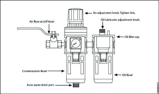
For best results use air hoses equal or larger than 3/4” internal diameter.
Use of a F.R.L. (Filter Regulator Lubricator) is highly recommended. Fill with oil and adjust the air admission with the adjustment knob.
Hydraulic Connections
Our hydraulic pumps are equipped with a zero-pressure relief valve. However, it could be possible that the retract side remain pressurized after the pump has been switched “off”. This trapped pressure prevents the user from loosening the retract-side fittings by hand. To release the pressure, simply push the black button on top of the solenoid. All fittings are free to be manually tightened.
Never disconnect or connect any hydraulic hoses or fittings without first unloading the wrench and the pump. If the system includes a gauge, double check the gauge to assure pressure has been released. When making connections with quick disconnect couplings, make sure the couplings are fully engaged. Závitové spoje ako fitingy, meradlá atď. musia byť čisté, pevne utiahnuté a bez netesností.
Pracovný tlak
The tool's maximum working pressure is 10,000 psi (700 bar). Make sure that all hydraulic equipment (pumps, hoses, couplers) used with this tool are rated for 10,000 psi (700 bar) working pressure. Review the documentation for the hydraulic pump in use to ensure pressure does not exceed 10,000 psi.
Connecting the System
The Atlas Copco hydraulic torque wrench and the power pack are connected by a 10,000 psi (700 bar) operating pressure twinline hose assembly. The safety ratio of the Atlas Copco hydraulic hose is 4/1. On each twin hydraulic hose, one line must be MALE-MALE and the other line must be FEMALE-FEMALE in order to assure a correct interaction between pump and machine. Connect the twinline hose to the swivel as shown:
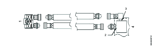
Referencia | Popis |
|---|---|
1 | Kľúč |
2 | Port 'A' |
3 | Port 'R' |
4 | Čerpadlo |
Check all coupler connections because, after the system has been pressurized, you will not be able to tighten the couplers by hand and using tools will damage the couplers.
Check all coupler connected properly with no gaps between collar and fittings. Never use spanners and other tools to tighten or loose couplers.
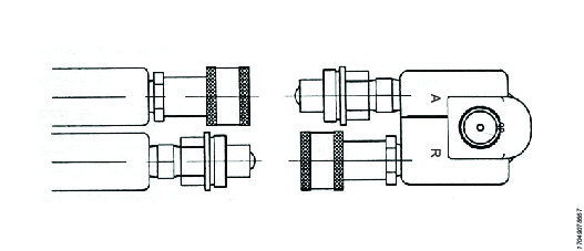
Ensure connectors are fully engaged and screwed snugly together.
Never use two twin hydraulic hoses between pump and machine. If so, you have the high pressure on the retract side and your machine will not work properly. To avoid tool malfunction, do not reverse connectors. Do not try to loosen the swivel assembly at any moment.
Operating Hydraulic Pump
Setting Working Pressure on the Pump
To set the pressure on the pump, follow this procedure:
Loosen the knurled locking ring below the "T" handle on the pump's external pressure regulator. Then turn the "T" handle counter clockwise (CCW) until it turns freely and easily.
Turn the pump "on". Using the pump's remote control pendant, push down the advance switch (or button on air pumps) and hold it.
While holding the pump in the advance mode, slowly turn the "T" handle clockwise and observe the pump pressure gauge rise.

Always adjust the regulator in order to increase the pressure up - Never down. Regulátor hydraulického tlaku nikdy nenastavujte pri spustenom nástroji.
When your gauge reaches 4,000 psi stop turning the "T" handle and let the gauge settle out.
If the pressure continues to rise (above 4,000 psi), release the advance button and back off your pressure slightly-by turning CCW on the "T" handle. Then re-depress the advance switch on you remote and slowly bring pressure up to 4,000 psi again.
When the pressure is correct, turn the pump "off" and tighten the knurled lock nut provided under the "T" handle. This sets pump pressure, which determines torque tool output.
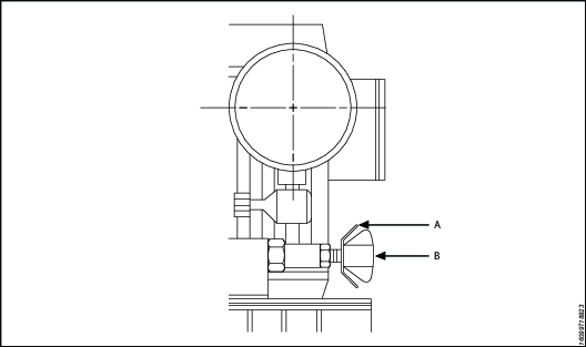
Referencia
Popis
A
Poistný krúžok
B
T - Handle
Once your target pressure is set and locked, cycle the pump once more to ensure that your pressure setting did not change as you turned down the knurled knob.
Applying Torque to Wrench
Having set your target pressure, cycle the tool three or four times to full pressure. Cycling the tool ensures that the system is operating properly and removes trapped air, if any.
Verify that any impact sockets used are rated to accept the full torque output of the tool they are to be used with. Ensure the correct size impact socket for the nut A/F has been selected, placed on the square drive and secure with a locking pin and ring.
Place the tool and the socket on the nut, making sure that the socket has fully engaged the nut, check that the drive retainer is engaged.
Uistite sa, či reakčné rameno pevne dosadá voči stacionárnemu predmetu (napr. priľahlá matica, príruba, schránka zariadenia a pod.). When positioning the wrench, make sure that the hose connections are well clear of any obstructions and that all body parts are safely out of harm's way. Vtedy, a len vtedy, aplikujte na systém chvíľkový tlak, aby ste zaistili správne umiestnenie nástroja. If it doesn't look or act right, stop and re-adjust the reaction arm.
Read Safety Instructions supplied with the torque wrench for further guidance on tool usage.
By pushing down on the remote control button in the advance position, the rear of the tool will be pushed back until its reaction arm will contact its reaction point.
Continue to hold down the button as the socket turns until you hear an audible "click" which will signify the hydraulic cylinder inside the tool is fully extended and will not turn the advance further.

Continuing to hold down the remote control button will result in a rapid build up of pressure to the point of where the gauge reads what was preset prior to applying the wrench.
The reading of full preset pressure after the cylinder is extended DOES NOT INDICATE that this pressure (torque) is applied to the bolt. It only indicates that the cylinder is fully extended and cannot turn the socket or the ratchet link further until the tool automatically resets itself.
Releasing the remote control button will retract the cylinder. The tool will automatically reset itself and the operator will hear an audible "click" indicating he can again push the remote control button and the socket will turn. Each time the cylinder is extended and retracted, it is called a cycle. Successive cycles are made until the tool "stalls" at the pre-set Torque/psi with an accuracy of +/-3%. Repeatability is +/- 1%.
Always attempt one final cycle to ensure the "stall" point has been reached.
Should the tool "lock-on" after the final cycle, push down on the remote control button once more (to build pressure) and, while maintaining this pressure, pull back on the external disengagement lever (RT) or reaction Pawl (RTX). Releasing the remote control while continuing to hold back on the pawl lever/reaction pawl will allow the tool to be removed easily.
Loosening Procedures
First, set the pump to 9,000 psi (Do not try directly at 10.000 psi). Change the drive and the reaction arm to the loosening mode (Left = Loose), assuring the reaction arm abuts squarely off a solid reaction point. Press and hold the remote control button down. Pressure will decrease as the socket begins to turn. As the cylinder extends fully, you will hear an audible "click". Release the remote control button, and the cylinder automatically retracts, at this time you will again hear the audible "click". Repeat this process until the fastener can be removed by hand.
If the bolt does not loosen with the above procedure, it is an indication that you need a larger tool to loosen the bolt.
Setting Torque
All Atlas Copco power packs operate at a pressure range from 500 to 10,000 psi and are fully adjustable. They have been engineered and designed for portability and high flow for increased speed. Before using your Atlas Copco power pack, check the following points.
Is the reservoir filled with oil?
Where is the closest electrical outlet at the job site?
Is there enough air pressure (60 to 100 psi) and Air flow at the job site? (Air units only)
Is the gauge mounted and rated for 10,000 psi / 700 bar?
Pracovný tlak
The pump's maximum working pressure is 10,000 psi / 700 bar. Make sure all hydraulic equipment and accessories are rated for 10,000 psi / 700 bar operating pressure. Hydraulic pumps are available with higher pressure outputs, if not using an Atlas Copco power pack verify maximum operating pressure of the unit being used and ensure the system maximum operating pressure (10,000 psi / 700 bar) is not exceeded.
Hydraulic Connections
Never disconnect or connect hydraulic hoses or fittings without first unloading the wrench. Unplug the electrical cord of the pump, and open all hydraulic controls several times to assure that the system has been depressurized. If the system includes a gauge, double check the gauge to assure pressure has been released. When making a connection with quick disconnect couplings, make sure the couplings are fully engaged threaded connections such a fittings, gauges etc. must be clean and securely tightened and leak free.
Loose or improperly threaded couplers can be potentially dangerous if pressurized, however, severe over tightening can cause premature thread failure. Fitingy musia byť utiahnuté pevne a bez netesností. Nikdy sa nedotýkajte, nepribližujte ani iným spôsobom neprichádzajte do kontaktu s hydraulickou tlakovou netesnosťou. Unikajúci olej môže preniknúť do pokožky a spôsobiť zranenie. Do not subject the hose and potential hazard such as sharp surfaces, extreme heat or heavy impact. Do not allow the hose to kink and twist. Inspect the hose for wear before it is used.
Electrical Power
Check the proper electrical supply before connecting.
This motor may spark. Do not operate in an explosive atmosphere or in pressure of conductive liquids.
Do not use a power or extension cord that is damaged or has exposed wiring.
All single phase motors come equipped with a three prong grounding type plus to fit the proper grounded type electrical outlet. Do not use a two prong ungrounded extension cord as the pump's motor must be grounded.
Compare motor nameplate against power availability to prevent motor burnout or dangerous electrical overloading.
Prior to Use
Check hydraulic oil (Use Atlas Copco maximiser range Grade 46) level to prevent possible pump burnout. Open the filler plug located on the reservoir plate. Look at oil fill level on the oil sight gauge. The oil level should be approximately 2" from the top of the reservoir plate- with motor off. Add oil as necessary. Do not mix different grades of oil. Make sure all desired gauge, valve, hose and quick coupler connections are tight and secure before operating. The use of a pressure gauge is required for normal pump operation. Mounted on the manifold, the gauge permits the operator to monitor the load on the wrench. Class1 certified calibrated gauges are available for most applications.
Operating Square Drive
Changing Drive Direction
To remove the square drive, push the round button on the drive retainer and gently pull on the square end of the square drive (for RT20, 25 & 50, push on the drive retainer while turning it counter-clockwise). To insert the drive in the tool, place the drive in the desired direction, engage drive and bushing splines, then twist drive and bushing until ratchet Spline can be engaged. Push drive through ratchet.
Push drive retainer button, engage retainer with drive and release button to lock the square drive in position.
Reaction Arm
All Atlas Copco hydraulic torque wrenches are equipped with a universal reaction arm. These reaction arms will absorb and counteract forces created as the unit operates. The reaction arm should extend in the same direction of the square drive; however, slight adjustments may be made to suit your particular application. The RT reaction arm is made of special aircraft alloy and is 360° adjustable.
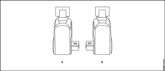
Referencia | Popis |
|---|---|
A | Right = Tight |
B | Left = Loose |
The standard RT reaction arm cannot be welded on and should not be modified.
The reaction arm for all RT Monobloc Housing is splined to slide over the rear (cylinder) portion of the tool. In operation, the reaction arm must be fully engaged and secured by inserting the spring loaded reaction arm lever at the base of the housing (end cap). Pred prevádzkou sa uistite, či je reakčné rameno úplne upevnené.
Setting Torque
Once the system is fully connected and proper power supply available, the operator may now adjust the pump pressure to the level needed for the application.
When tightening, use the manufacturer's specifications to determine the torque value which you will ultimately require.
Torque sequence may vary from plant to plant and even within individual plants, depending upon the gasket material, etc. Always follow local procedures.
Refer to the pressure-torque conversion table applicable to the tool which you intend to use, Torque chats are available on ServAId .
Square/Allen Drive Working Torque
Veľkosť upínadla The square or hex drive of each drive is limited in its maximum output by its material and its engagement area. Since Atlas Copco uses a specially suited alloy-steel for its drive members, the following maximum torque output can be achieved without drive failure, provided the reaction member abuts close to the same plane as the nut to be turned.
If the reaction arm cannot abut on the same plane as the nut to be turned, less torque should be applied, as the additional side load has to be taken into consideration. When toque requirements are close in excess of the values listed above, use RT's/-9/ Sockets Hex-Drive with replaceable Hex Insert Bits.
RT series is available with square drive (standard) or option hexagonal/Allen drive. The table below reviews ideal working range for the respective drives.
Veľkosť upínadla Inch or mm | Typ upínadla | Maximálny pracovný tlak | Probable Failure | ||
ft lb | Nm | ft lb | Nm | ||
1/2’ | Hex | 353 | 478 | 392 | 531 |
1/2’ | Square | 367 | 497 | 408 | 553 |
5/8” | Hex | 689 | 934 | 766 | 1038 |
3/4’ | Hex | 1191 | 1614 | 1324 | 1794 |
3/4’ | Square | 1239 | 1679 | 1377 | 1865 |
7/8” | Hex | 1892 | 2565 | 2102 | 2848 |
1" | Hex | 2824 | 3827 | 3138 | 4252 |
1" | Square | 2937 | 3980 | 3263 | 4422 |
1-1-8 | Hex | 4021 | 5448 | 4468 | 6054 |
1-1-4 | Hex | 5516 | 7474 | 6129 | 8304 |
1-3-8 | Hex | 7341 | 9948 | 8157 | 11053 |
1-1-2 | Hex | 9531 | 12915 | 10590 | 14350 |
1-1-2 | Square | 9912 | 13432 | 11014 | 14924 |
1-5-8 | Hex | 12118 | 16420 | 13465 | 18245 |
1-3-4 | Hex | 15135 | 20508 | 16817 | 22787 |
1-7-8 | Hex | 18616 | 25224 | 20684 | 28027 |
2" | Hex | 22593 | 30613 | 25103 | 34015 |
2-1-4 | Hex | 32168 | 43588 | 35742 | 48431 |
2-1-2 | Hex | 44126 | 59791 | 49029 | 66435 |
2-1-2 | Square | 45891 | 62183 | 50990 | 69092 |
12mm | Hex | 298 | 404 | 331 | 449 |
17mm | Hex | 847 | 1147 | 941 | 1275 |
19mm | Hex | 1182 | 1602 | 1313 | 1780 |
22mm | Hex | 1835 | 2486 | 2039 | 2763 |
24mm | Hex | 2382 | 3228 | 2647 | 3587 |
27mm | Hex | 3392 | 4596 | 3769 | 5107 |
32mm | Hex | 5647 | 7652 | 6275 | 8502 |
36mm | Hex | 8040 | 10895 | 8934 | 12105 |
41mm | Hex | 11878 | 16094 | 13197 | 17882 |
46mm | Hex | 16774 | 22730 | 18638 | 25255 |
50mm | Hex | 21542 | 29190 | 23935 | 32433 |
Servis
Návod na údržbu
Odporúčania pre servis a údržbu
Pri prevádzke, oprave alebo údržbe nástroja alebo v ich blízkosti alebo pri výmene príslušenstva nástroja vždy používajte ochranu očí a tváre odolnú voči nárazom.
Všetky inšpekčné, údržbárske a opravárske práce by sa mali vykonávať, len keď je celý systém na nulovom tlaku.
Pre optimálny výkon často vizuálne kontrolujte, či nie sú poškodené nástroj, hydraulická jednotka, hadice, konektory, elektrické káble a príslušenstvo. Vždy dodržiavajte pokyny pre údržbu nástroja a čerpadla.
Usmernenie k servisným intervalom
Vyškolený personál so správnym plánom údržby môže hydraulické kľúče používať dlhé roky bez problémov. Všetky nástroje sa však po dlhom používaní opotrebujú. Faktory, ktoré ovplyvňujú životnosť nástroja:
Vysoká frekvencia cyklov
Používanie pri vysokom zaťažení
Vplyv
Prevádzka v špinavom, horúcom alebo vlhkom prostredí
Rôzne reakčné metódy
Zlá údržba
Odporúča sa pravidelné mazanie a prehliadky, aby sa zaistilo, že kľúč zostane v dobrom prevádzkovom stave. Ak kľúč používate pri vysokých uťahovacích momentoch, vysokej frekvencii cyklov alebo dlhých časoch uťahovania, budú potrebné častejšie servisné intervaly. Ak kľúč nepracuje správne, okamžite ho nechajte skontrolovať.
Nasledujúce servisné intervaly sú len orientačné. Každý prípad použitia a aplikácia sú odlišné, takže je na zodpovednosti koncového používateľa vykonávať vhodnú plánovanú údržbu špecifickú vzhľadom na pracovné prostredie a použitie. Viesť záznamy o prevádzke nástroja. Tento záznam pomáha plánovať servis, kalibráciu a výmenu nástroja alebo komponentov.
Malé zaťaženie
Príklad: Málo časté používanie pri nízkych tlakoch, <40 % kapacity.
Mazanie: každých 6 mesiacov
Prehliadka: každých 12 mesiacov
Normálne zaťaženie
Príklad: Pravidelné používanie, <80 % kapacity.
Mazanie: každých 3 mesiacov
Prehliadka: každých 12 mesiacov vrátane výmeny kolíkov upínadla. Pozri oddiel Mazanie.
Veľké zaťaženie
Príklad: Stále používanie pri akomkoľvek tlaku, použitie >80 % kapacity; pravidelné používanie pri uvoľňovaní skorodovaných skrutiek.
Mazanie: každý 1 mesiac
Prehliadka: každých 6 mesiacov vrátane výmeny kolíkov upínadla a západky upínadla. Pozri oddiel Mazanie.
Výmena nástroja
Vlastník produktu je povinný zaviesť servisný plán pre politiku výmeny nástrojov. Táto politika zabezpečuje, aby sa prevádzkové nástroje vymenili skôr, ako sa nástroj prestane používať. Vzhľadom na rôzne prevádzkové prostredia a možné nezrovnalosti v servise nástrojov je ťažké definovať ich životnosť.
Vizuálne známky opotrebovania, ako sú jazvy, preliačiny alebo chýbajúci materiál, naznačujú, že nástroj už nie je použiteľný. Servisujte nástroje, ktoré vykazujú známky opotrebovania. Aby boli nástroje v stave vhodné pre používanie, vymeňte všetky poškodené časti. Ak nástroj vykazuje väčšie poškodenie súčastí obsahujúcich tlak alebo reakčných ramien, správnym opatrením je z bezpečnostných dôvodov nástroj odstrániť.
Bližšie informácie nájdete v časti Usmernenie k servisným intervalom.
Preventívna údržba
Na udržiavanie hydraulického systému momentového kľúča v dobrom prevádzkovom stave vykonajte po každom období používania nasledujúce kroky údržby.
Utrite všetky vonkajšie povrchy a vizuálne skontrolujte nástroj, či nevykazuje známky poškodenia. V prípade potreby to preskúmajte.
Prezrite všetky hydraulické spoje a prípojky, či nevykazujú známky hydraulických netesností. V prípade potreby to preskúmajte.
Uistite sa, že všetky hydraulické spojky sú čisté a bez úlomkov.
Skontrolujte celú dĺžku hadice; hľadajte porezané alebo odreté miesta. Venujte osobitnú pozornosť zúženým koncom a hľadajte akékoľvek známky netesností.
Ak je vybavenie v dobrom prevádzkovom stave, nastriekajte ho vhodným antikoróznym olejom, ako napríklad Shell Ensis alebo Castrol Rustillo, a uskladnite ho na ďalšie použitie.
Pokyny na prehliadku
Pripojte kľúč k čerpadlu.
Vykonajte tlakovú skúšku, aby ste sa uistili, že všetky mechanizmy fungujú podľa očakávaní.
Preskúmajte všetky poruchy alebo hydraulické netesnosti.
Odtlakujte systém a odpojte všetky spojky.
Rozmontujte kľúč.
Vymeňte všetky tesnenia a pružiny.
Vymeňte kolík upínadla.
Vymeňte všetky ostatné komponenty, ktoré vykazujú známky poškodenia alebo opotrebovania.
Znova namažte a zmontujte kľúč.
Vykonajte tlakovú skúšku a uistite sa, že všetky mechanizmy fungujú podľa očakávaní.
Nakalibrujte kľúč a uistite sa, že výstupný uťahovací moment je podľa očakávaní.
Návod na mazanie
Odporúčané mazivá
Komponenty upínadla | Molykote 1000 |
Tesnenia | Rocol Sapphire Aqua-Sil |
Upevňovacie prvky | Loctite 243 |
Skosené hydraulické závity | Loctite 577 |
Mazanie
Na udržanie kľúčov v dobrom prevádzkovom stave pravidelne mažte komponenty upínadla medzi servisnými intervalmi.
Demontáž pred mazaním:
Odstráňte štvorcové upínadlo.
Odstráňte prístupové zátky [×2].
Odstráňte skrutky ochranného plášťa [×2] a ochranný plášť.
Odstráňte poistné spony [×2].
Odstráňte puzdrá upínadla [×2].
Umiestnite kolík upínadla v jednej línii s otvorom prístupovej zátky. Vysunutím kolíka z telesa uvoľnite zostavu upínadla.
Odstráňte zostavu upínadla z telesa.
Vykonajte nasledujúce činnosti počas mazacej údržby:
Prezrite kolík upínadla, či nevykazuje známky opotrebovania alebo poškodenia. V prípade potreby kolík vymeňte.
Prezrite hrany zubov račne, či nevykazujú známky poškodenia. V prípade potreby račňu vymeňte.
Prezrite zuby západky upínadla, či nevykazujú známky poškodenia. V prípade potreby západku upínadla vymeňte.
Prezrite pružiny západky upínadla, či nevykazujú známky poškodenia. V prípade potreby pružiny vymeňte.
Namažte tieňované oblasti prostriedkom Molykote 1000.
Postup montáže je rovnaký ako pri demontáži, ale v opačnom poradí.
Riešenie problémov
Troubleshooting of Hydraulic Torque Wrench
Tool failure, although rare, does occur. Such failure is most often in the hydraulic couplers or hoses. These items are repairable or replaceable immediately, since they are available universally. Failures of structural members of the tool are quite rare, however, replacement parts are available from stock. All repairs to Atlas Copco tools may be made by reasonably experienced individuals according to the aforementioned instructions. Otherwise, please contact Atlas Copco to schedule a quick repair of the tool.
Recommended Service intervals are :
Heavy duty use or use in corrosive/harsh environments – every 3 months internal drive components may require frequent inspection and re-lubrication under heavy duty cycles, e.g. weekly.
Normal use – every 6 months.
Light or infrequent use – every 12 months.
Troubleshooting Powerpacks
Atlas Copco Hydraulic Power Packs are precision-built units and, as such, do require a certain amount of care and maintenance
Hydraulic Oil should be completely changed after every 300 hours of operation, or at least twice a year. Always make sure the reservoir is filled with fluid. Always use Atlas Copco Maximizer range of oils for best performance.
Couplers and fittings should be checked periodically for leaks. Dirt or foreign materials should be kept away from fittings. Clean before use.
Hydraulic Gauge: Some gauges are liquid filled. Should this liquid level drop, it indicates external leakage, and replacement is necessary. Should the gauge fill with hydraulic oil, it indicates internal failure and it should be discarded.
Filter on Pump: The filter should be replaced twice a year in normal use and more often if the pump is used daily or in a dirty, harsh environment.
Diaľkové ovládanie (Air Unit) The airline to the remote control unit should be checked for obstructions or kinks in the line periodically. If there is a bend or break in the line, it must be replaced. The spring- loaded buttons on the remote handle should be checked in the event of operating difficulties. (Electric Unit) The switch buttons should be checked periodically if any indications of problems exist.
Air Valve: This valve should be checked twice a year.
Armature: (Electric Unit) Check yearly.
Pumping unit: The pump should be overhauled every 2 years. This can be done by Atlas Copco or by a qualified hydraulic service centre.
Troubleshooting Routines
Test 1
Attach hoses to pump and tool in the normal manner.
Press the advance button and hold it down.
If the pump pressure builds and the hoses "flex" but the tool still refuses to cycle, the problem is most likely a loose or defective coupling connection. To find out where the bad coupling is, remove the tool from the hoses and marry the loose ends together and cycle the pump. If the gauge pressure reads no more than 500 PSI, then the bad fitting is on the tool. A significantly greater pressure indicates that the problem is in either the pump or a hose fitting.
Test 2
Remove screws from pump motor to reservoir, slide pump motor to the back while keeping pistons into oil.
Turn pump on. If you have no oil coming out from the solenoid tube, change the solenoid.
Tight the regulating valve to maximum, Push on the advance button and while holding down, look if any oil is coming out from the regulating tube. If oil is coming out, change the regulating valve.
Test 3
Remove tool from hoses.
Cycle pump.
If pump fails to build pressure, the problem is with the pump. If it does build pressure, the problem is with hydraulic blow-by in the tool.
Test 4
This test should be run prior to every use of an Atlas Copco Tool
Connect the tool, pump and hoses together as normal.
Cycle the pump several times.
Cycle the system once more and observe the sequence of operation.
As you depress the advance button, the tool drive shroud turn about 24 degrees and you should hear an audible "click". You will also notice that the disengagement levers will move to the rear of the tool and spring forward.
At this point, release the advance button. You should see no further movement and after a moment you will hear another audible "click". This is how the tools are designed to operate.
If you observe any other sequence of operation, the system is out of order and cannot deliver more than 10% of its designed capacity.
Take immediate corrective action. For reference, tools and pumps are designed from the factory plumbed as follows. This ensures that the tool, pump and ONE hose cannot possible be connected up incorrectly.
Test 5
Nástroj | Hadica | Čerpadlo |
|---|---|---|
Advanced Side-Male | Advance side- Female to Female | Advance side-Male |
Retract side-Female | Retract Side-Male to Male | Retract Side-Female |
Note that connecting two (or any even numbers) of hoses together creates "one" hose which is plumbed backwards! Male to Female and Female to Male. This will cause the system to operate backwards per Test #5 above. If you hose isn’t long enough, connect 3 hoses together, move your pump or call Atlas Copco for a longer hose assembly.
Symptómy problémov a požadovaná akcia
Symptom | Probable Cause | Required Action |
|---|---|---|
Gauge shows pressure build-up but the tool will not cycle | Couplings are loose or not working. Solenoid is not working | Tighten and/or replace couplings. Use Test #1 to isolate problem Use test #2. if not working replace solenoid |
Cylinder will not retract | 1.See above. | 1. See above. |
2.Voltage to electric pump is too low to line drop or inadequate amperage is available. | 2. Get shorter extension cord or upgrade to 12AWG, 25 amp rating or better. | |
3.Linkage between piston rod and drive pawl are broken. | 3. Vymeňte valec podľa potreby. | |
Cylinder pressure will not build | 1. Oil blow by in tool (Piston seal leak, blown O-ring, cracked piston) | 1. Replace defective parts. Obráťte sa na zástupcu spoločnosti Atlas Copco. |
2. Pump Problem. | 2. Remove screws from pump motor to reservoir, slide pump motor to the back while keeping pistons into oil. Turn pump on. If you have no oil coming out from the solenoid tube, change the solenoid. 2A If pump sounds like a lot of pebbles in a tin can, the problem may be a worn motor coupling-remove motor from base plate-using a pair of needle nose pliers removes the motor coupling-if worn replace. Obráťte sa na zástupcu spoločnosti Atlas Copco. 2B If pump sounds like a lot of pebbles in a tin can, the problem may be a worn motor coupling-remove motor from base plate-using a pair of needle nose pliers removes the motor coupling-if worn replace. Obráťte sa na zástupcu spoločnosti Atlas Copco. 2C. Air pump- Fault FRL due to excessive moisture and/or dirt in air supply. Disassemble and change. Obráťte sa na zástupcu spoločnosti Atlas Copco. 2D. Air pumps- Replace faulty remote control valve cartridge. | |
Cylinder/tool leaks | 1. Safety relief valve on swivel has lifted. | 1A Tighten all hose and couplers. If leak continues, adjust safety setting – Test #4. 1B Check to see if the system is properly plumbed by running test #5 (high pressure on retract side will lift the safety relief valve). |
2. Blown O-ring in cylinder. | 2. Replace O-Ring with proper high pressure O-Ring. Obráťte sa na zástupcu spoločnosti Atlas Copco. | |
3.Defective gland seal. | 3. Replace gland seal. Obráťte sa na zástupcu spoločnosti Atlas Copco. | |
Tool operates backwards | 1. Couplings reversed. | 1. Run test #5. Replumb system as necessary. |
2. Multiple hoses in even numbers. | 2. As plumbed, Atlas Copco hoses may only be joined together in odd numbers ONLY if it is necessary to use 2, 4, 6 hoses-make an adapter from spare high pressure couplings and nipples. | |
Ratchet returns with retract stroke | Broken or otherwise inoperable reaction pawl. | |
Ratchet will not take successive strokes. | 1. Broken or otherwise inoperative drive pawl or spring. | 1. Replace drive pawl and/or spring. Obráťte sa na zástupcu spoločnosti Atlas Copco. |
2. Cylinder not retracting completely. Ratchet will not take successive strokes. | 2.Remove tool from nut and cycle freely for several strokes. If problem persists, check pawls. 2A Operator not allowing adequate time for cylinder to retract fully | |
3. Linkage between piston rod and drive plates is broken. | 3. Replace parts as necessary -Contact Atlas Copco service. | |
Tool locks onto nut. | 1. Reaction pawl is loaded when the tool is maxed out in torque. | 1. Press advance button on remote and build pressure- continue to press down on remote while pulling back on one of the disengagement levers- release remote while continuing to hold back on levers. |
2. Tool is operating backwards. | 2. Push advance button down-tool should immediately fall free- Run test #5. | |
3.Tool is wedged under a fixed object. | 3. Remove shroud from around ratchet. Using any tool available, pry the drive pawl out of the ratchet and at the same time pull back on the disengagement levers. Tool should swing free or turn away the socket or obstruction. | |
Gauge records no pressure | 1. Gauge connection is loose. | 1. Tighten coupling. |
2. Bad gauge. | 2. Replace gauge. | |
3. Pump will not build pressure. | 3. See cylinder will not build pressure above. See cylinder will not build pressure above. | |
4. Tools seals are blown. | 4. Replace defective seals. Obráťte sa na zástupcu spoločnosti Atlas Copco. |
Symptómy problémov a požadovaná akcia
Symptom | Probable Cause | Required Action |
|---|---|---|
Pump will not build pressure. | 1. Air Electric supply is low. | 1. Skontrolujte regulátor tlaku vzduchu |
2. Defective relief or regulator valve. | 2. Replace valve. Obráťte sa na zástupcu spoločnosti Atlas Copco. | |
3. Low oil or clogged filter. | 3. Fill reservoir and clean filter. | |
4. Internal leak in oil line from external relief valve to pump body. | 4. Open reservoir, inspect oil line while trying to build pressure- if leaking tighten fittings or replace. | |
5. Defective Solenoid or regulating valve. | 5. See “Cylinder will not build pressure-#2 above” | |
Motor sluggish and inefficient “sounds sick” slow to build pressure. | 1. Air or electric supply is low. | 1. See #1 in preceding block |
2. Clogged filter. | 2. Vyčistite alebo vymeňte filtre | |
Pump heats up. | 1. Improper use. | 1. Operator is continuing to hold down on the advance stroke after the cylinder has reached end of stroke- this causes a lot of oil to go through a very small hole in relief-valve- causing heat build-up. Have operator release advance stroke after disengagement levers spring forward. |
2. Remote control is left in “on” position when pump is not actively in use. | 2. Turn pump off whenever not actually being used. DO NOT leave pump running when tool is not in use. | |
Pump cannot reach 10,000 psi, only 9,000psi | Change regulating valve | 1A.Remove 3 screws of 4 port block manifold IB. Remove regulating valve IC: Replace new regulating valve ID. Don’t forget metal ring IE. Check o’rings on block manifold IF. Replace block manifold IG. Place 1 drop of loctite on each screw IH. Tighten screws firmly - double check screws are fully tightened. |
Pressure can’t reach 4,000 psi | Change cut off valve(s) | IA. Remove the pump from tank IB. Change cut-off valves 3,250 psi /70 bar 90% Chance pump is workingIB. Change cut-off valves 3,250 psi /70 bar 90% Chance pump is working IC: If pump can’t get 10,000 psi change cut-off valve 1,250 psi/350 bar |
Pressure not stable (big variation) | Change solenoid (115v), (220v) | IA. Remove top solenoid IB. Replace new top solenoid IC: Poškodené tesniace krúžky |
Pressure not stable (small variation) | Change check valves Part# 20374 Need special tooling | IA. Remove the pump from tank IB. Replace check valve IC: Do not tight too much |
No pressure | Check piping | IA. Remove the pump from tank or Check piping couplers IB. Check t-coupler inside the pump |
Uncontrolled pressure | 1. Check coupling Part#10190 | IA. Remove the pump from the tank IB. Remove piping IC: Remove block pump (screws# 20444) ID. Check attentively coupling IE. Do not forget to replace keys(part #10184) |
2. Check pumps Part# 10168-10169-10170 | 2A Remove the pump from the tank 2B Untighten pump’s screws 2C. Check seals 2D. Vymeniť 2E. Tighten firmly |
Symptómy problémov a požadovaná akcia
Symptom | Probable Cause | Required Action |
|---|---|---|
Motor doesn’t run | 1.Check fuse 16 a Part# 10064 | 1. Change fuse 16 a (white - on top) |
2. Check electrical box | 2. Check for disconnection | |
3. Check 115v cord | 3.Check for wire cut or disconnect | |
4. Check plug | 4. Check for wire disconnect | |
5.Check remote control | 5. Check for wire disconnect | |
Motor start difficult | 1. Bearing Part#10198 & 10178 | IA. Remove the pump from the tank IB. Remove block pump IC: Disassemble block pump ID. Change bearing |
2. Remote control handswitch small white plastic support | 2A Open the hand switch 2B. Replace small plastic parts | |
Blown fuses when starting | Check if fuse 16 a is blown Part# 10064 | To avoid the problem don’t run motor If hydraulic hose are not connected |
Hose or tool fitting is damaged or leaks. | 1. Broken or melted plastic outer covering. | 1. If underlying plastic is still intact continue operation. Inspect frequently.If underlying plastic is still intact continue operation. Inspect frequently. |
2. Frayed plastic strands. | 2. Cut hose in half and discard. Replace hose. | |
3. Oil leaks through fibres. | 3. Cut hose in half and discard. Replace hose. | |
4. Broken fittings. | 4. Remove old fitting and replace with STEEL high pressure fittings only. After changing fittings, always run test #5 to insure proper plumbing. | |
Electric pump will not run | 1. Loose electric connections in control box. | 1. Open control box and visually inspect for loose threaded or push-on connectors. |
2. Motor burned up. | 2. Replace motor components whichever is necessary. Obráťte sa na zástupcu spoločnosti Atlas Copco. | |
Fuse | 3. Change defect fuse |
Recyklácia
Environmentálne predpisy
Keď výrobok splnil svoj účel, musí byť správne recyklovaný. Demontujte výrobok a recyklujte jeho komponenty v súlade s miestnou legislatívou.