Square Drive Tool
Hydraulic Torque Wrench
제품 정보
일반 정보
버리지 마십시오 – 사용자에게 주십시오
용도 선언
전문 용도로만 사용해 주세요.
이 제품과 그 부속품을 변형시켜서는 안 됩니다.
이 제품이 손상된 경우 사용하지 마십시오.
제품 데이터 또는 위험 경고 징후가 보이거나 확실한 경우, 기다리지 말고 즉시 교체하십시오.
The product must only be operated and serviced by trained and qualified personnel.
안전 신호 용어
안전 신호 용어인 위험, 경고, 주의, 및 참고에는 다음과 같은 의미가 있습니다.
위험 | 위험은 위험한 상황을 나타내며 이러한 상황을 피하지 않으면 사망 또는 중상으로 이어집니다. |
경고 | 경고는 위험한 상황을 나타내며 이러한 상황을 피하지 않으면 사망 또는 중상으로 이어질 가능성이 있습니다. |
주의 | 안전 경보 기호와 함께 사용되는 주의는 위험한 상황을 나타내며 이러한 상황을 피하지 않으면 중경상으로 이어질 가능성이 있습니다. |
참고 | 참고는 신체 상해와 관련이 없는 실제적인 문제를 해결하는 데 사용됩니다. |
보증
제품 보증은 제품을 처음 사용한 후 12개월에 만료되지만 인도 후 어떤 일이 있어도 늦어도 13개월 내에 만료됩니다.
정상적인 부품의 마모는 보증에 포함되지 않습니다.
일상적인 마모에 의한 손상은 해당 기간의 일반적인 표준 공구 유지보수 동안(시간, 작동 시간 또는 다른 방법으로 표시됨) 부품 변경 또는 기타 조정/점검이 필요한 것입니다.
제품 보증은 공구와 구성 부품의 정확한 사용, 유지 및 수리에 의존합니다.
보증 기간 동안 부적합한 유지나 Atlas Copco 또는 공인 서비스 협력 업체 외에서 정비를 수행한 결과로 발생한 부품 손상은 보증이 적용되지 않습니다.
공구 부품이 손상되거나 파괴되지 않도록 하려면, 권장된 유지 보수 일정에 따라 공구를 정비하고 정확한 지침을 준수하십시오.
보증 수리는 Atlas Copco 정비소 또는 인증 서비스 협력업체에서만 수행됩니다
는 Atlas Copco 계약을 통해 연장된 보증과 최첨단의 예방 정비를 제공합니다. ToolCover. 추가 정보는 가까운 서비스 대리점에 문의하십시오.
전기 모터의 경우:
전기 모터가 열리지 않았을 경우에만 보증이 적용됩니다.
ServAid
ServAid는 지속적으로 업데이트되며 다음과 같은 기술 정보가 포함된 포털입니다.
규정 및 안전 정보
기술 자료
설치, 작동 및 서비스 지침
예비 부품 목록
부속품
축적 도면
다음 자료 및 웹 사이트를 참조해 주세요. https://servaid.atlascopco.com.
추가 정보는 가까운 Atlas Copco 서비스 대리점에 문의하십시오.
안전 보건 자료 MSDS/SDS
Atlas Copco가 판매하는 화학 제품에 대한 설명은 안전 데이터 시트에 나와 있습니다.
자세한 정보는 Atlas Copco 웹사이트 www.atlascopco.com/sds를 방문해주십시오.
원산지 국가
원산지 국가에 대한 정보는 제품 라벨의 해당 정보를 참조해주십시오.
축적 도면
치수 도면은 치수 도면 아카이브 또는 ServAid에서 찾을 수 있습니다.
다음 자료 및 웹 사이트를 참조해 주세요. http://webbox.atlascopco.com/webbox/dimdrw 또는 https://servaid.atlascopco.com.
개요
제품의 기술 데이터
기술 제품 데이터는 ServAid 또는 Atlas Copco 웹사이트에서 찾을 수 있습니다.
다음 자료 및 웹 사이트를 참조해 주세요. https://servaid.atlascopco.com 또는 www.atlascopco.com.
서비스 개요
서비스 권장 사항
정기적으로 예방 유지보수를 할 것을 권장합니다. 예방 유지보수에 대한 자세한 정보를 참조하십시오. 제품이 제대로 작동하지 않을 경우, 서비스를 신청하여 점검을 받으세요.
예방 유지보수에 대한 자세한 정보가 포함되어 있지 않은 경우, 다음과 같은 일반 지침을 따르십시오.
적절한 부품을 꼼꼼하게 청소합니다.
결함이 있거나 마모된 부품은 교체해 주세요.
작동
인체공학적 지침
본 일반 인체공학적 지침 목록을 읽고 귀하의 작업장을 고려하여, 자세, 구성품 배치 또는 작업 환경의 개선 대상 영역을 확인하십시오.
휴식을 자주 취하고 작업 자세를 자주 바꾸십시오.
작업장 영역을 본인의 필요 및 작업에 맞게 조정하십시오.
정적인 동작을 피하려면 부품이나 공구가 어디에 위치해야 하는지 파악하여 편리한 동선으로 조정해야 합니다.
테이블 및 의자와 같이 작업에 적절한 작업장 장비를 사용하십시오.
어깨 높이보다 높은 작업 자세 또는 조립 작업 중에 정적인 상태를 유지해야 하는 자세는 피하십시오.
어깨 높이보다 높은 곳에서 작업할 때 토크 암, 호스 릴 또는 중량 밸런서와 같은 도구를 이용하여 중량을 줄임으로써 움직임이 없는 어깨 위로 가해지는 부하를 줄이십시오. 또한 도구를 몸 가까이 잡는 것으로도 움직임이 없는 어깨 위로 가해지는 부하를 줄일 수 있습니다.또한 부하물을 몸 가까이 잡는 것으로도 움직임이 없는 근육에 가해지는 부하를 줄일 수 있습니다.
자주 휴식을 취해야합니다.
팔이나 손목을 지나치게 뻗는 자세는 피해야 하며, 특히 어느 정도의 힘을 필요로 하는 작업을 수행하는 동안에는 절대 삼가십시오.
최소한으로 눈과 머리를 움직일 수 있는 편리한 시야로 조정하십시오.
작업을 수행할 때 적절한 조명을 사용하십시오.
작업을 수행할 때 적절한 공구를 사용하십시오.
소음이 심한 환경에서는, 귀 보호 장비를 사용하십시오.
고급 인서트 공구 및 소모품을 사용하여 과도한 진동에 최대한 노출되지 않도록 하십시오.
작동 지침
Electric Connections
Ensure proper power availability to prevent motor failure or dangerous electrical overloading. Use the recommended amperage listed on the motor nameplate. Do not use electric pump if ground is not connected on plug.
연장 전선의 길이를 최소화하고 선 크기가 적절한지 그리고 접지되어 있는지 확인해 주세요.
Extension cord should be #10 AWG gauge.
General Setup
All our hydraulic torque wrenches are supplied completely assembled, ready for use. An Atlas Copco hydraulic power pack, for use with your Atlas Copco hydraulic torque wrench, is recommended to provide the speed, pressure and portability that make your Atlas Copco System efficient and accurate.
The accuracy of your Atlas Copco hydraulic torque wrench is +/-3% based upon our manufacturer's specifications. This accuracy is certified through calibration tests conducted by Atlas Copco or any other qualified calibration facility whose program is traceable to the National Institute of Standards and Technology (N.I.S.T). We strongly suggest using Atlas Copco certified gauges (with a class 1 accuracy) to enhance the accuracy your torquing system.
공기 연결부
Ensure that you have sufficient air flow (58 up to 100 PSI / 4 up to 7 bar) to operate you pneumatic pump. If in doubt, compare the pump manufacturer's recommended air flow rating prior to pressurizing pump. Improper air flow may damage the pump motor.
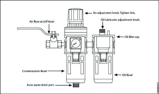
For best results use air hoses equal or larger than 3/4” internal diameter.
Use of a F.R.L. (Filter Regulator Lubricator) is highly recommended. Fill with oil and adjust the air admission with the adjustment knob.
Hydraulic Connections
Our hydraulic pumps are equipped with a zero-pressure relief valve. However, it could be possible that the retract side remain pressurized after the pump has been switched “off”. This trapped pressure prevents the user from loosening the retract-side fittings by hand. To release the pressure, simply push the black button on top of the solenoid. All fittings are free to be manually tightened.
Never disconnect or connect any hydraulic hoses or fittings without first unloading the wrench and the pump. If the system includes a gauge, double check the gauge to assure pressure has been released. When making connections with quick disconnect couplings, make sure the couplings are fully engaged. 피팅, 게이지 등과 같은 나사 연결부는 깨끗하고 확실히 조인 상태이어야 하며 새지 않아야 합니다.
작동 압력
The tool's maximum working pressure is 10,000 psi (700 bar). Make sure that all hydraulic equipment (pumps, hoses, couplers) used with this tool are rated for 10,000 psi (700 bar) working pressure. Review the documentation for the hydraulic pump in use to ensure pressure does not exceed 10,000 psi.
Connecting the System
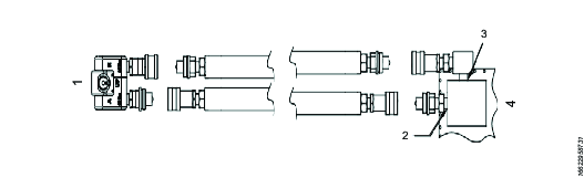
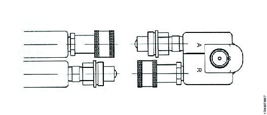
The Atlas Copco hydraulic torque wrench and the power pack are connected by a 10,000 psi (700 bar) operating pressure twinline hose assembly. The safety ratio of the Atlas Copco hydraulic hose is 4/1. On each twin hydraulic hose, one line must be MALE-MALE and the other line must be FEMALE-FEMALE in order to assure a correct interaction between pump and machine. Connect the twinline hose to the swivel as shown:
참조 | 설명 |
|---|---|
1 | 렌치 |
2 | 포트 A |
3 | Port 'R' |
4 | 펌프 |
Check all coupler connections because, after the system has been pressurized, you will not be able to tighten the couplers by hand and using tools will damage the couplers.
Check all coupler connected properly with no gaps between collar and fittings. Never use spanners and other tools to tighten or loose couplers.
Ensure connectors are fully engaged and screwed snugly together.
Never use two twin hydraulic hoses between pump and machine. If so, you have the high pressure on the retract side and your machine will not work properly. To avoid tool malfunction, do not reverse connectors. Do not try to loosen the swivel assembly at any moment.
Operating Hydraulic Pump
Setting Working Pressure on the Pump
To set the pressure on the pump, follow this procedure:
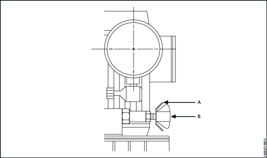
Loosen the knurled locking ring below the "T" handle on the pump's external pressure regulator. Then turn the "T" handle counter clockwise (CCW) until it turns freely and easily.
Turn the pump "on". Using the pump's remote control pendant, push down the advance switch (or button on air pumps) and hold it.
While holding the pump in the advance mode, slowly turn the "T" handle clockwise and observe the pump pressure gauge rise.

Always adjust the regulator in order to increase the pressure up - Never down. 적용 분야에서 도구를 사용하는 유압 압력 조정기를 조절하지 마세요.
When your gauge reaches 4,000 psi stop turning the "T" handle and let the gauge settle out.
If the pressure continues to rise (above 4,000 psi), release the advance button and back off your pressure slightly-by turning CCW on the "T" handle. Then re-depress the advance switch on you remote and slowly bring pressure up to 4,000 psi again.
When the pressure is correct, turn the pump "off" and tighten the knurled lock nut provided under the "T" handle. This sets pump pressure, which determines torque tool output.
참조
설명
A
잠금 링
B
T - Handle
Once your target pressure is set and locked, cycle the pump once more to ensure that your pressure setting did not change as you turned down the knurled knob.
Applying Torque to Wrench
Having set your target pressure, cycle the tool three or four times to full pressure. Cycling the tool ensures that the system is operating properly and removes trapped air, if any.
Verify that any impact sockets used are rated to accept the full torque output of the tool they are to be used with. Ensure the correct size impact socket for the nut A/F has been selected, placed on the square drive and secure with a locking pin and ring.
Place the tool and the socket on the nut, making sure that the socket has fully engaged the nut, check that the drive retainer is engaged.
리액션 암이 고정되어 있는 물체에 단단히 붙어 있는지 확인해 주세요. (예: 인접 너트, 플랜지, 장비 외장 등) When positioning the wrench, make sure that the hose connections are well clear of any obstructions and that all body parts are safely out of harm's way. 이후 그런 다음에만 시스템에 순간적으로 압력을 가해 공구 위치가 올바른지 확인하세요. If it doesn't look or act right, stop and re-adjust the reaction arm.
Read Safety Instructions supplied with the torque wrench for further guidance on tool usage.
By pushing down on the remote control button in the advance position, the rear of the tool will be pushed back until its reaction arm will contact its reaction point.
Continue to hold down the button as the socket turns until you hear an audible "click" which will signify the hydraulic cylinder inside the tool is fully extended and will not turn the advance further.

Continuing to hold down the remote control button will result in a rapid build up of pressure to the point of where the gauge reads what was preset prior to applying the wrench.
The reading of full preset pressure after the cylinder is extended DOES NOT INDICATE that this pressure (torque) is applied to the bolt. It only indicates that the cylinder is fully extended and cannot turn the socket or the ratchet link further until the tool automatically resets itself.
Releasing the remote control button will retract the cylinder. The tool will automatically reset itself and the operator will hear an audible "click" indicating he can again push the remote control button and the socket will turn. Each time the cylinder is extended and retracted, it is called a cycle. Successive cycles are made until the tool "stalls" at the pre-set Torque/psi with an accuracy of +/-3%. Repeatability is +/- 1%.
Always attempt one final cycle to ensure the "stall" point has been reached.
Should the tool "lock-on" after the final cycle, push down on the remote control button once more (to build pressure) and, while maintaining this pressure, pull back on the external disengagement lever (RT) or reaction Pawl (RTX). Releasing the remote control while continuing to hold back on the pawl lever/reaction pawl will allow the tool to be removed easily.
Loosening Procedures
First, set the pump to 9,000 psi (Do not try directly at 10.000 psi). Change the drive and the reaction arm to the loosening mode (Left = Loose), assuring the reaction arm abuts squarely off a solid reaction point. Press and hold the remote control button down. Pressure will decrease as the socket begins to turn. As the cylinder extends fully, you will hear an audible "click". Release the remote control button, and the cylinder automatically retracts, at this time you will again hear the audible "click". Repeat this process until the fastener can be removed by hand.
If the bolt does not loosen with the above procedure, it is an indication that you need a larger tool to loosen the bolt.
Seating torque (시팅 토크)
All Atlas Copco power packs operate at a pressure range from 500 to 10,000 psi and are fully adjustable. They have been engineered and designed for portability and high flow for increased speed. Before using your Atlas Copco power pack, check the following points.
Is the reservoir filled with oil?
Where is the closest electrical outlet at the job site?
Is there enough air pressure (60 to 100 psi) and Air flow at the job site? (Air units only)
Is the gauge mounted and rated for 10,000 psi / 700 bar?
작동 압력
The pump's maximum working pressure is 10,000 psi / 700 bar. Make sure all hydraulic equipment and accessories are rated for 10,000 psi / 700 bar operating pressure. Hydraulic pumps are available with higher pressure outputs, if not using an Atlas Copco power pack verify maximum operating pressure of the unit being used and ensure the system maximum operating pressure (10,000 psi / 700 bar) is not exceeded.
Hydraulic Connections
Never disconnect or connect hydraulic hoses or fittings without first unloading the wrench. Unplug the electrical cord of the pump, and open all hydraulic controls several times to assure that the system has been depressurized. If the system includes a gauge, double check the gauge to assure pressure has been released. When making a connection with quick disconnect couplings, make sure the couplings are fully engaged threaded connections such a fittings, gauges etc. must be clean and securely tightened and leak free.
Loose or improperly threaded couplers can be potentially dangerous if pressurized, however, severe over tightening can cause premature thread failure. 피팅은 확실히 조인 상태이어야 하며 새지 않아야 합니다. 유압이 샌다면 절대 잡거나 만지지 말고 접촉해서도 안 됩니다. 새는 오일이 피부로 침투해 부상을 초래할 수 있습니다. Do not subject the hose and potential hazard such as sharp surfaces, extreme heat or heavy impact. Do not allow the hose to kink and twist. Inspect the hose for wear before it is used.
Electrical Power
Check the proper electrical supply before connecting.
This motor may spark. Do not operate in an explosive atmosphere or in pressure of conductive liquids.
Do not use a power or extension cord that is damaged or has exposed wiring.
All single phase motors come equipped with a three prong grounding type plus to fit the proper grounded type electrical outlet. Do not use a two prong ungrounded extension cord as the pump's motor must be grounded.
Compare motor nameplate against power availability to prevent motor burnout or dangerous electrical overloading.
Prior to Use
Check hydraulic oil (Use Atlas Copco maximiser range Grade 46) level to prevent possible pump burnout. Open the filler plug located on the reservoir plate. Look at oil fill level on the oil sight gauge. The oil level should be approximately 2" from the top of the reservoir plate- with motor off. Add oil as necessary. Do not mix different grades of oil. Make sure all desired gauge, valve, hose and quick coupler connections are tight and secure before operating. The use of a pressure gauge is required for normal pump operation. Mounted on the manifold, the gauge permits the operator to monitor the load on the wrench. Class1 certified calibrated gauges are available for most applications.
Operating Square Drive
Changing Drive Direction
To remove the square drive, push the round button on the drive retainer and gently pull on the square end of the square drive (for RT20, 25 & 50, push on the drive retainer while turning it counter-clockwise). To insert the drive in the tool, place the drive in the desired direction, engage drive and bushing splines, then twist drive and bushing until ratchet Spline can be engaged. Push drive through ratchet.
Push drive retainer button, engage retainer with drive and release button to lock the square drive in position.
Reaction Arm
All Atlas Copco hydraulic torque wrenches are equipped with a universal reaction arm. These reaction arms will absorb and counteract forces created as the unit operates. The reaction arm should extend in the same direction of the square drive; however, slight adjustments may be made to suit your particular application. The RT reaction arm is made of special aircraft alloy and is 360° adjustable.
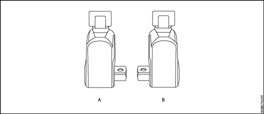
참조 | 설명 |
|---|---|
A | Right = Tight |
B | Left = Loose |
The standard RT reaction arm cannot be welded on and should not be modified.
The reaction arm for all RT Monobloc Housing is splined to slide over the rear (cylinder) portion of the tool. In operation, the reaction arm must be fully engaged and secured by inserting the spring loaded reaction arm lever at the base of the housing (end cap). 리액션 암이 완전히 체결되어 있는지 작동 전에 확인해 주세요.
Seating torque (시팅 토크)
Once the system is fully connected and proper power supply available, the operator may now adjust the pump pressure to the level needed for the application.
When tightening, use the manufacturer's specifications to determine the torque value which you will ultimately require.
Torque sequence may vary from plant to plant and even within individual plants, depending upon the gasket material, etc. Always follow local procedures.
Refer to the pressure-torque conversion table applicable to the tool which you intend to use, Torque chats are available on ServAId .
Square/Allen Drive Working Torque
드라이브 크기 The square or hex drive of each drive is limited in its maximum output by its material and its engagement area. Since Atlas Copco uses a specially suited alloy-steel for its drive members, the following maximum torque output can be achieved without drive failure, provided the reaction member abuts close to the same plane as the nut to be turned.
If the reaction arm cannot abut on the same plane as the nut to be turned, less torque should be applied, as the additional side load has to be taken into consideration. When toque requirements are close in excess of the values listed above, use RT's/-9/ Sockets Hex-Drive with replaceable Hex Insert Bits.
RT series is available with square drive (standard) or option hexagonal/Allen drive. The table below reviews ideal working range for the respective drives.
드라이브 크기 Inch or mm | 드라이브 유형 | 최대 작동 압력 | Probable Failure | ||
ft lb | Nm | ft lb | Nm | ||
1/2" | 육각 | 353 | 478 | 392 | 531 |
1/2" | 사각판 | 367 | 497 | 408 | 553 |
5/8" | 육각 | 689 | 934 | 766 | 1038 |
3/4" | 육각 | 1191 | 1614 | 1324 | 1794 |
3/4" | 사각판 | 1239 | 1679 | 1377 | 1865 |
7/8" | 육각 | 1892 | 2565 | 2102 | 2848 |
1" | 육각 | 2824 | 3827 | 3138 | 4252 |
1" | 사각판 | 2937 | 3980 | 3263 | 4422 |
1 - 1/8" | 육각 | 4021 | 5448 | 4468 | 6054 |
1 - 1/4" | 육각 | 5516 | 7474 | 6129 | 8304 |
1 - 3/8" | 육각 | 7341 | 9948 | 8157 | 11053 |
1 - 1/2" | 육각 | 9531 | 12915 | 10590 | 14350 |
1 - 1/2" | 사각판 | 9912 | 13432 | 11014 | 14924 |
1 - 5/8" | 육각 | 12118 | 16420 | 13465 | 18245 |
1 - 3/4" | 육각 | 15135 | 20508 | 16817 | 22787 |
1 - 7/8" | 육각 | 18616 | 25224 | 20684 | 28027 |
2" | 육각 | 22593 | 30613 | 25103 | 34015 |
2 - 1/4" | 육각 | 32168 | 43588 | 35742 | 48431 |
2 - 1/2" | 육각 | 44126 | 59791 | 49029 | 66435 |
2 - 1/2" | 사각판 | 45891 | 62183 | 50990 | 69092 |
12mm | 육각 | 298 | 404 | 331 | 449 |
17mm | 육각 | 847 | 1147 | 941 | 1275 |
19mm | 육각 | 1182 | 1602 | 1313 | 1780 |
22mm | 육각 | 1835 | 2486 | 2039 | 2763 |
24mm | 육각 | 2382 | 3228 | 2647 | 3587 |
27mm | 육각 | 3392 | 4596 | 3769 | 5107 |
32mm | 육각 | 5647 | 7652 | 6275 | 8502 |
36mm | 육각 | 8040 | 10895 | 8934 | 12105 |
41mm | 육각 | 11878 | 16094 | 13197 | 17882 |
46mm | 육각 | 16774 | 22730 | 18638 | 25255 |
50mm | 육각 | 21542 | 29190 | 23935 | 32433 |
서비스
유지보수 지침
서비스 및 유지보수 권장 사항
작업을 하거나 근처에 있을 경우, 공구의 수리나 유지보수 시 혹은 공구의 부속품 교체 시에는, 항상 내충격 눈 및 안면 보호 장비를 착용해야 합니다.
모든 조사, 유지보수 또는 수리 작업은 전체 시스템의 압력이 0일 때에만 수행해야 합니다.
최적의 성능을 위해, 공구, 파워 팩, 호스, 커넥터, 전선 및 부속품이 손상되지 않았는지 자주 육안 검사해 주세요. 공구 및 펌프의 적절한 유지보수를 위해 항상 지침을 따르십시오.
서비스 주기 지침
올바른 유지보수 일정을 가진 교육을 받은 인원은 수년간 유압 렌치를 문제없이 사용할 수 있습니다. 그렇지만, 모든 공구는 장기간 사용 후에는 마모됩니다. 공구 수명에 영향을 주는 인자:
높은 사이클 속도
높은 하중 사용
영향
불결하고 고온이거나 습한 환경
다양한 리액션 방법
유지보수 불량
렌치가 양호한 작동 상태를 유지하도록 정기적인 윤활 및 정밀 검사를 수행하시는 것을 권장합니다. 토크가 높고 사이클 율이 높거나 조임 시간이 긴 환경에서 렌치를 사용하는 경우, 분해검사를 더 자주 해야 할 수도 있습니다. 렌치가 올바르게 작동하지 않는 경우, 즉시 분리하여 검사해야 합니다.
다음 서비스 주기는 참고용으로만 사용하십시오. 각 사용 사례와 응용 분야는 다르기 때문에 작업 환경 및 용도에 맞게 적절하게 계획한 유지관리 작업을 시행하는 것은 최종 사용자의 책임입니다. 공구 작업에 대한 기록을 보관합니다. 이 기록은 공구나 구성품의 정비, 교정 및 교체 계획을 수립하는 데 도움이 됩니다.
가벼운 작업
예: 저압에서 자주 사용하지 않음. <40% 용량.
윤활: 6개월마다
정밀 검사: 12개월마다
정상 작업
예: 일반 사용, <80% 용량.
윤활: 3개월마다
정밀 검사: 12개월마다(드라이브 핀 교체 포함) 윤활 섹션을 참조하십시오.
강력 작업
예: 어떤 압력에서도 지속적으로 사용, > 80% 용량 사용, 부식된 볼트를 푸는 작업에 정기적으로 사용.
윤활: 1개월마다
정밀 검사: 6개월마다(드라이브 핀 및 드라이브 폴 교체 포함) 윤활 섹션을 참조하십시오.
공구 교체
제품 소유자는 공구 교체 정책에 대한 정비 계획을 시행해야 합니다. 이 정책은 공구를 더 이상 사용할 수 없게 되기 전에 작동 공구를 교체하도록 보장해야 합니다. 다양한 작동 환경 및 공구 정비의 잠재적인 불일치로 인해 공구 수명을 정의하기는 어렵습니다.
흠, 움푹 들어간 부분 또는 결손된 소재와 같은 눈에 띄는 마모 징후는 공구를 더 이상 사용할 수 없음을 나타냅니다. 마모 징후를 보여주는 공구는 정비하십시오. 공구의 상태를 유지하려면 손상된 부품을 교체하십시오. 공구에서 압력이 걸리는 구성품 또는 리액션 암에 중대한 손상이 보이는 경우 안전을 위해 시정 조치를 취해 공구를 제거해야 합니다.
자세한 정보는 정비 간격 지침을 참조하십시오.
예방 유지보수
유압 토크 렌치 시스템을 양호한 작동 상태로 유지하려면 각 사용 기간 후에 다음 유지보수 단계를 수행하십시오.
모든 외부 표면을 닦고 육안으로 공구 손상 여부를 검사해 주세요. 필요한 경우 정밀 조사를 수행해 주세요.
모든 유압 조인트 및 연결부에서 유압 누출 징후가 있는지 검사하십시오. 필요한 경우 정밀 조사를 수행해 주세요.
모든 유압 커플링이 깨끗하고 이물질이 없는지 확인해 주세요.
호스의 전체 길이를 검사하고 잘리거나 마모된 부분이 있는지 확인해 주세요. 스웨이지 끝단에 주의하여 누출의 징후가 있는지 확인해 주세요.
장비의 작동 상태가 양호하면 Shell Ensis 또는 Castrol Rustillo와 같은 적합한 녹 방지제 오일을 도포하고 다음에 사용할 수 있도록 보관해 주세요.
정밀 검사 지침
렌치를 펌프에 연결하십시오.
압력 테스트를 통해 모든 장치가 예상대로 작동하는지 꼭 확인해 주세요.
오작동 또는 유압 누출을 조사하십시오.
시스템을 감압하고 모든 커플링을 분리해야 합니다.
렌치를 분해하십시오.
모든 씰과 스프링을 교체하십시오.
드라이브 핀을 교체하십시오.
손상 또는 마모의 징후가 있는 다른 구성 요소는 모두 교체해야 합니다.
렌치를 다시 윤활 처리하고 재조립하십시오.
압력 테스트를 통해 모든 장치가 예상대로 작동하는지 꼭 확인해 주세요.
렌치를 교정하여 토크 출력이 예상 값과 같은지 꼭 확인해 주세요.
윤활 지침
윤활 안내
드라이브 부품 | Molykote 1000 |
씰 | Rocol Sapphire Aqua-Sil |
패스너 | Loctite 243 |
테이퍼 유압 나사산 | Loctite 577 |
윤활
렌치를 양호한 작동 상태로 유지하려면 서비스 주기 사이에 드라이브 구성 요소를 정기적으로 윤활하십시오.
윤활 전 분해:
스퀘어 드라이브를 분리합니다.
액세스 플러그(×2)를 제거합니다.
슈라우드 나사[×2] 및 슈라우드를 분리합니다.
리테이닝 클립[×2]을 분리합니다.
드라이브 슬리브[×2]를 분리합니다.
드라이브 핀을 액세스 플러그 구멍에 맞춰 놓아주세요. 하우징에서 핀을 밀어 드라이브 조립품을 분리합니다.
하우징에서 드라이브 조립품을 분리합니다.
윤활 유지보수 중에 다음 작업을 수행하십시오.
드라이브 핀에 마모 또는 손상의 징후가 있는지 검사합니다. 필요한 경우 핀을 교체하십시오.
래칫 톱니 가장자리에 손상 징후가 있는지 검사합니다. 필요한 경우 래칫을 교체해 주세요.
드라이브 폴 톱니에 손상 징후가 있는지 검사합니다. 필요한 경우 드라이브 폴을 교체하십시오.
드라이브 폴 스프링에 손상 징후가 있는지 검사합니다. 필요한 경우 스피링을 교체하십시오.
Molykote 1000로 음영 처리된 부분을 윤활 처리해 주세요.
조립 절차는 분해 절차와 동일하지만 역방향으로 진행해 주세요.
문제 진단
Troubleshooting of Hydraulic Torque Wrench
Tool failure, although rare, does occur. Such failure is most often in the hydraulic couplers or hoses. These items are repairable or replaceable immediately, since they are available universally. Failures of structural members of the tool are quite rare, however, replacement parts are available from stock. All repairs to Atlas Copco tools may be made by reasonably experienced individuals according to the aforementioned instructions. Otherwise, please contact Atlas Copco to schedule a quick repair of the tool.
Recommended Service intervals are :
Heavy duty use or use in corrosive/harsh environments – every 3 months internal drive components may require frequent inspection and re-lubrication under heavy duty cycles, e.g. weekly.
Normal use – every 6 months.
Light or infrequent use – every 12 months.
Troubleshooting Powerpacks
Atlas Copco Hydraulic Power Packs are precision-built units and, as such, do require a certain amount of care and maintenance
Hydraulic Oil should be completely changed after every 300 hours of operation, or at least twice a year. Always make sure the reservoir is filled with fluid. Always use Atlas Copco Maximizer range of oils for best performance.
Couplers and fittings should be checked periodically for leaks. Dirt or foreign materials should be kept away from fittings. Clean before use.
Hydraulic Gauge: Some gauges are liquid filled. Should this liquid level drop, it indicates external leakage, and replacement is necessary. Should the gauge fill with hydraulic oil, it indicates internal failure and it should be discarded.
Filter on Pump: The filter should be replaced twice a year in normal use and more often if the pump is used daily or in a dirty, harsh environment.
리모컨 (Air Unit) The airline to the remote control unit should be checked for obstructions or kinks in the line periodically. If there is a bend or break in the line, it must be replaced. The spring- loaded buttons on the remote handle should be checked in the event of operating difficulties. (Electric Unit) The switch buttons should be checked periodically if any indications of problems exist.
Air Valve: This valve should be checked twice a year.
Armature: (Electric Unit) Check yearly.
Pumping unit: The pump should be overhauled every 2 years. This can be done by Atlas Copco or by a qualified hydraulic service centre.
Troubleshooting Routines
Test 1
Attach hoses to pump and tool in the normal manner.
Press the advance button and hold it down.
If the pump pressure builds and the hoses "flex" but the tool still refuses to cycle, the problem is most likely a loose or defective coupling connection. To find out where the bad coupling is, remove the tool from the hoses and marry the loose ends together and cycle the pump. If the gauge pressure reads no more than 500 PSI, then the bad fitting is on the tool. A significantly greater pressure indicates that the problem is in either the pump or a hose fitting.
Test 2
Remove screws from pump motor to reservoir, slide pump motor to the back while keeping pistons into oil.
Turn pump on. If you have no oil coming out from the solenoid tube, change the solenoid.
Tight the regulating valve to maximum, Push on the advance button and while holding down, look if any oil is coming out from the regulating tube. If oil is coming out, change the regulating valve.
Test 3
Remove tool from hoses.
Cycle pump.
If pump fails to build pressure, the problem is with the pump. If it does build pressure, the problem is with hydraulic blow-by in the tool.
Test 4
This test should be run prior to every use of an Atlas Copco Tool
Connect the tool, pump and hoses together as normal.
Cycle the pump several times.
Cycle the system once more and observe the sequence of operation.
As you depress the advance button, the tool drive shroud turn about 24 degrees and you should hear an audible "click". You will also notice that the disengagement levers will move to the rear of the tool and spring forward.
At this point, release the advance button. You should see no further movement and after a moment you will hear another audible "click". This is how the tools are designed to operate.
If you observe any other sequence of operation, the system is out of order and cannot deliver more than 10% of its designed capacity.
Take immediate corrective action. For reference, tools and pumps are designed from the factory plumbed as follows. This ensures that the tool, pump and ONE hose cannot possible be connected up incorrectly.
Test 5
공구 | 호스 | 펌프 |
|---|---|---|
Advanced Side-Male | Advance side- Female to Female | Advance side-Male |
Retract side-Female | Retract Side-Male to Male | Retract Side-Female |
Note that connecting two (or any even numbers) of hoses together creates "one" hose which is plumbed backwards! Male to Female and Female to Male. This will cause the system to operate backwards per Test #5 above. If you hose isn’t long enough, connect 3 hoses together, move your pump or call Atlas Copco for a longer hose assembly.
문제 해결 및 필요한 조치
증상 | Probable Cause | Required Action |
|---|---|---|
Gauge shows pressure build-up but the tool will not cycle | Couplings are loose or not working. Solenoid is not working | Tighten and/or replace couplings. Use Test #1 to isolate problem Use test #2. if not working replace solenoid |
Cylinder will not retract | 1.See above. | 1. See above. |
2.Voltage to electric pump is too low to line drop or inadequate amperage is available. | 2. Get shorter extension cord or upgrade to 12AWG, 25 amp rating or better. | |
3.Linkage between piston rod and drive pawl are broken. | 3. 필요한 경우 실린더를 교체해 주세요. | |
Cylinder pressure will not build | 1. Oil blow by in tool (Piston seal leak, blown O-ring, cracked piston) | 1. 기계 부품 교체 Atlas Copco 담당자에게 문의해 주세요. |
2. Pump Problem. | 2. Remove screws from pump motor to reservoir, slide pump motor to the back while keeping pistons into oil. Turn pump on. If you have no oil coming out from the solenoid tube, change the solenoid. 2A If pump sounds like a lot of pebbles in a tin can, the problem may be a worn motor coupling-remove motor from base plate-using a pair of needle nose pliers removes the motor coupling-if worn replace. Atlas Copco 담당자에게 문의해 주세요. 2B If pump sounds like a lot of pebbles in a tin can, the problem may be a worn motor coupling-remove motor from base plate-using a pair of needle nose pliers removes the motor coupling-if worn replace. Atlas Copco 담당자에게 문의해 주세요. 2C. Air pump- Fault FRL due to excessive moisture and/or dirt in air supply. Disassemble and change. Atlas Copco 담당자에게 문의해 주세요. 2D. Air pumps- Replace faulty remote control valve cartridge. | |
Cylinder/tool leaks | 1. Safety relief valve on swivel has lifted. | 1A Tighten all hose and couplers. If leak continues, adjust safety setting – Test #4. 1B Check to see if the system is properly plumbed by running test #5 (high pressure on retract side will lift the safety relief valve). |
2. Blown O-ring in cylinder. | 2. Replace O-Ring with proper high pressure O-Ring. Atlas Copco 담당자에게 문의해 주세요. | |
3.Defective gland seal. | 3. Replace gland seal. Atlas Copco 담당자에게 문의해 주세요. | |
Tool operates backwards | 1. Couplings reversed. | 1. Run test #5. Replumb system as necessary. |
2. Multiple hoses in even numbers. | 2. As plumbed, Atlas Copco hoses may only be joined together in odd numbers ONLY if it is necessary to use 2, 4, 6 hoses-make an adapter from spare high pressure couplings and nipples. | |
Ratchet returns with retract stroke | Broken or otherwise inoperable reaction pawl. | |
Ratchet will not take successive strokes. | 1. Broken or otherwise inoperative drive pawl or spring. | 1. Replace drive pawl and/or spring. Atlas Copco 담당자에게 문의해 주세요. |
2. Cylinder not retracting completely. Ratchet will not take successive strokes. | 2.Remove tool from nut and cycle freely for several strokes. If problem persists, check pawls. 2A Operator not allowing adequate time for cylinder to retract fully | |
3. Linkage between piston rod and drive plates is broken. | 3. Replace parts as necessary -Contact Atlas Copco service. | |
Tool locks onto nut. | 1. Reaction pawl is loaded when the tool is maxed out in torque. | 1. Press advance button on remote and build pressure- continue to press down on remote while pulling back on one of the disengagement levers- release remote while continuing to hold back on levers. |
2. Tool is operating backwards. | 2. Push advance button down-tool should immediately fall free- Run test #5. | |
3.Tool is wedged under a fixed object. | 3. Remove shroud from around ratchet. Using any tool available, pry the drive pawl out of the ratchet and at the same time pull back on the disengagement levers. Tool should swing free or turn away the socket or obstruction. | |
Gauge records no pressure | 1. Gauge connection is loose. | 1. Tighten coupling. |
2. Bad gauge. | 2. Replace gauge. | |
3. Pump will not build pressure. | 3. See cylinder will not build pressure above. See cylinder will not build pressure above. | |
4. Tools seals are blown. | 4. Replace defective seals. Atlas Copco 담당자에게 문의해 주세요. |
문제 해결 및 필요한 조치
증상 | Probable Cause | Required Action |
|---|---|---|
Pump will not build pressure. | 1. Air Electric supply is low. | 1. 공기 압력 조정기 점검 |
2. Defective relief or regulator valve. | 2. Replace valve. Atlas Copco 담당자에게 문의해 주세요. | |
3. Low oil or clogged filter. | 3. Fill reservoir and clean filter. | |
4. Internal leak in oil line from external relief valve to pump body. | 4. Open reservoir, inspect oil line while trying to build pressure- if leaking tighten fittings or replace. | |
5. Defective Solenoid or regulating valve. | 5. See “Cylinder will not build pressure-#2 above” | |
Motor sluggish and inefficient “sounds sick” slow to build pressure. | 1. Air or electric supply is low. | 1. See #1 in preceding block |
2. Clogged filter. | 2. 필터 청소 또는 교체 | |
Pump heats up. | 1. Improper use. | 1. Operator is continuing to hold down on the advance stroke after the cylinder has reached end of stroke- this causes a lot of oil to go through a very small hole in relief-valve- causing heat build-up. Have operator release advance stroke after disengagement levers spring forward. |
2. Remote control is left in “on” position when pump is not actively in use. | 2. Turn pump off whenever not actually being used. DO NOT leave pump running when tool is not in use. | |
Pump cannot reach 10,000 psi, only 9,000psi | Change regulating valve | 1A.Remove 3 screws of 4 port block manifold Ib Remove regulating valve IC: Replace new regulating valve ID Don’t forget metal ring IE. Check o’rings on block manifold IF. Replace block manifold IG. Place 1 drop of loctite on each screw IH. Tighten screws firmly - double check screws are fully tightened. |
Pressure can’t reach 4,000 psi | Change cut off valve(s) | IA. Remove the pump from tank Ib Change cut-off valves 3,250 psi /70 bar 90% Chance pump is workingIB. Change cut-off valves 3,250 psi /70 bar 90% Chance pump is working IC: If pump can’t get 10,000 psi change cut-off valve 1,250 psi/350 bar |
Pressure not stable (big variation) | Change solenoid (115v), (220v) | IA. Remove top solenoid Ib Replace new top solenoid IC: o-링이 손상됨 |
Pressure not stable (small variation) | Change check valves Part# 20374 Need special tooling | IA. Remove the pump from tank Ib Replace check valve IC: Do not tight too much |
No pressure | Check piping | IA. Remove the pump from tank or Check piping couplers Ib Check t-coupler inside the pump |
Uncontrolled pressure | 1. Check coupling Part#10190 | IA. Remove the pump from the tank Ib Remove piping IC: Remove block pump (screws# 20444) ID Check attentively coupling IE. Do not forget to replace keys(part #10184) |
2. Check pumps Part# 10168-10169-10170 | 2A Remove the pump from the tank 2B Untighten pump’s screws 2C. Check seals 2D. 교체 2E. Tighten firmly |
문제 해결 및 필요한 조치
증상 | Probable Cause | Required Action |
|---|---|---|
Motor doesn’t run | 1.Check fuse 16 a Part# 10064 | 1. Change fuse 16 a (white - on top) |
2. Check electrical box | 2. Check for disconnection | |
3. Check 115v cord | 3.Check for wire cut or disconnect | |
4. Check plug | 4. Check for wire disconnect | |
5.Check remote control | 5. Check for wire disconnect | |
Motor start difficult | 1. Bearing Part#10198 & 10178 | IA. Remove the pump from the tank Ib Remove block pump IC: Disassemble block pump ID Change bearing |
2. Remote control handswitch small white plastic support | 2A Open the hand switch 2B. Replace small plastic parts | |
Blown fuses when starting | Check if fuse 16 a is blown Part# 10064 | To avoid the problem don’t run motor If hydraulic hose are not connected |
Hose or tool fitting is damaged or leaks. | 1. Broken or melted plastic outer covering. | 1. If underlying plastic is still intact continue operation. Inspect frequently.If underlying plastic is still intact continue operation. Inspect frequently. |
2. Frayed plastic strands. | 2. Cut hose in half and discard. Replace hose. | |
3. Oil leaks through fibres. | 3. Cut hose in half and discard. Replace hose. | |
4. Broken fittings. | 4. Remove old fitting and replace with STEEL high pressure fittings only. After changing fittings, always run test #5 to insure proper plumbing. | |
Electric pump will not run | 1. Loose electric connections in control box. | 1. Open control box and visually inspect for loose threaded or push-on connectors. |
2. Motor burned up. | 2. Replace motor components whichever is necessary. Atlas Copco 담당자에게 문의해 주세요. | |
퓨즈 | 3. 퓨즈를 바꿉니다. |